Case Design for Pi1541 Zero & Epyx Fastload Combo Cartridge

Making Of / 14 July 2020

Hello, 

I made a case design for one of my friends' electronic component which is a both floppy drive emulator and a fastload cartridge for Commodore C64.

This time video is more explanatory then the blog content :)

This is the actual electronic part:


And this is my design:

Some assemble instruction I made:

And photos of the final product:


Electronic part can be purchased by this link:

https://www.ebay.co.uk/itm/Pi1541-Zero-Epyx-Fastload-Combo-Cartridge-for-Commodore-64-C64-SD2IEC-alt/133457648596

3d printable case is available free here:

https://www.thingiverse.com/thing:4541283

What is Pi1541 - https://cbm-pi1541.firebaseapp.com/ 

What is Epyx Fast Load - https://en.wikipedia.org/wiki/Epyx_Fast_Load


Creating Pixel Art with Commodore 64 Limitations

Article / 15 June 2020


Recently I got myself into some pixelart studies by doing it with Commodore 64 Multi Color limitations.

Let me tell you about this limitations. 

1. Fixed Color Pallette

Commodore 64 has a fixed 16 color pallette. Which is a strange choice of colors that made by the developers of the product.

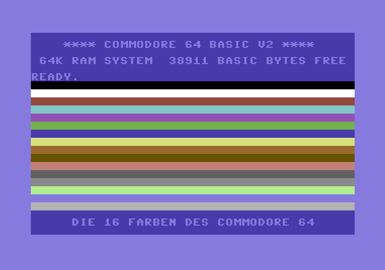
For more info: https://www.c64-wiki.com/wiki/Color 

2. Resolution drop on multi color painting

Standard resolution of the Commodore 64 is 320 x 200 pixel. And C64 has 2 different bitmap modes. 

a. Hi-Res Mode

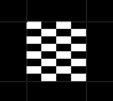
Resolution that meant by "Hi-Res" is 320 x 200 screen. To paint in this resolution, normally you can only use 2 colors in every 8 x 8 pixels block. You can't put a third color into a block if there is already 2 different colors are used there without totally overriding one of the existing colors on that block.

It maybe high (!) on resolution but it's very hard to create art with switcing colors in every block smoothly.

For more info: https://www.c64-wiki.com/wiki/Standard_Bitmap_Mode

b. Multi-Color Mode

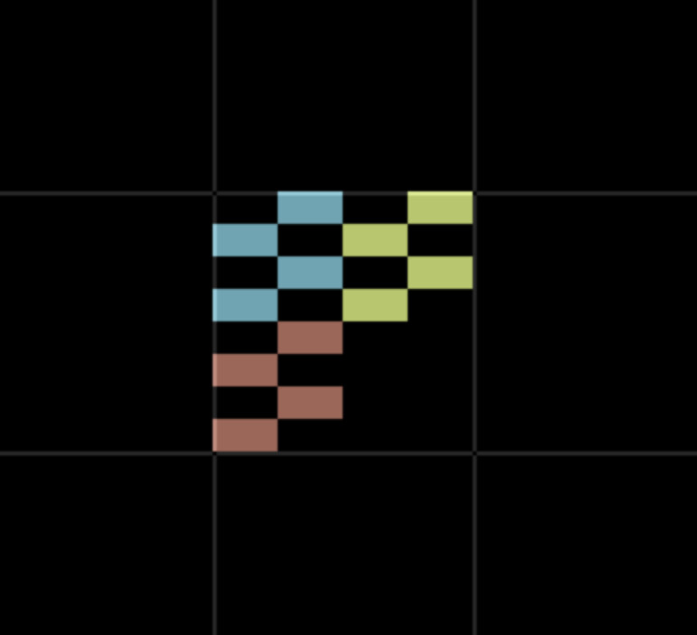
To create a bitmap with multi color combinations, C64 needs to limit it's resolution to 160 x 200 pixels by halving the horizontal pixel count by defining 1 x 1 pixel as 2 x 1 pixel.

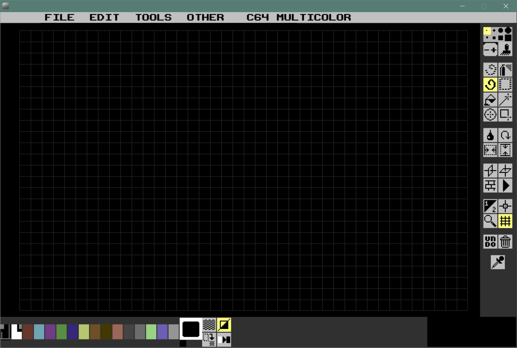
Grid in this picture shows square area of 8 x 8 pixels. But you can see that since 1 pixels are 2 pixels wide, 8 x 8 area can only be represented by 4 x 8 pixels. I prefered to make my work on this mode.

For more info: https://www.c64-wiki.com/wiki/Multicolor_Bitmap_Mode 

3. Color Count Limitation

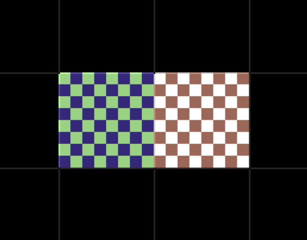
Third and final limitation in Multicolor Mode is the color count in every 8 x 8 pixel block. You can use up to 4 different colors in every block, but one of this 4 colors should be a pre-defined fixed color in every block. Which is called "background color". By another means, you can use 3 different colors and 1 fixed background color.

In this picture you can see that I used 3 colors and additional Black color as background color.

After this 3 limitations you can create your pixel art for Commodore 64. 

I used Multipaint Software for windows for this process. It is very useful and nice designed software for several graphics modes not just for C64 but for many 8-bit computers.

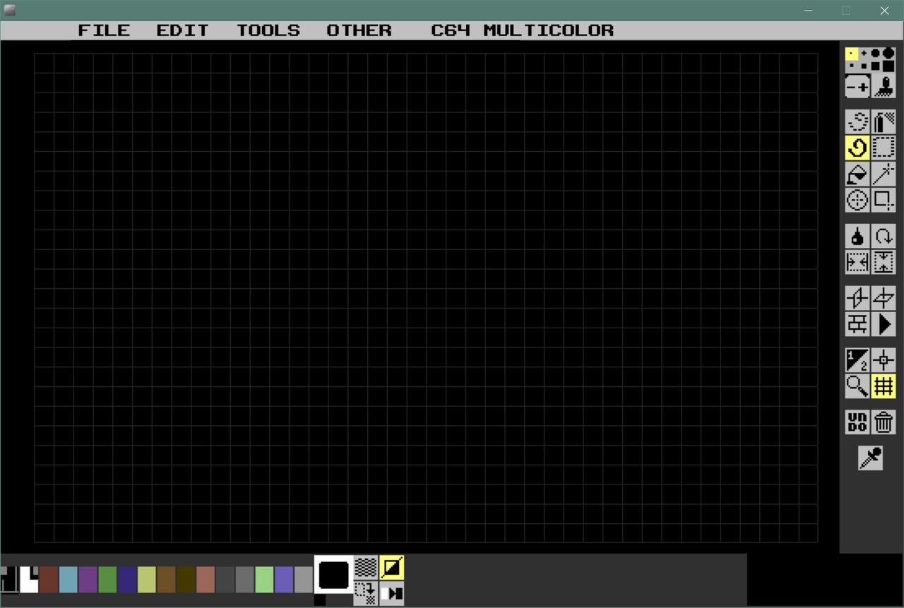
Software homapage: http://multipaint.kameli.net/ 

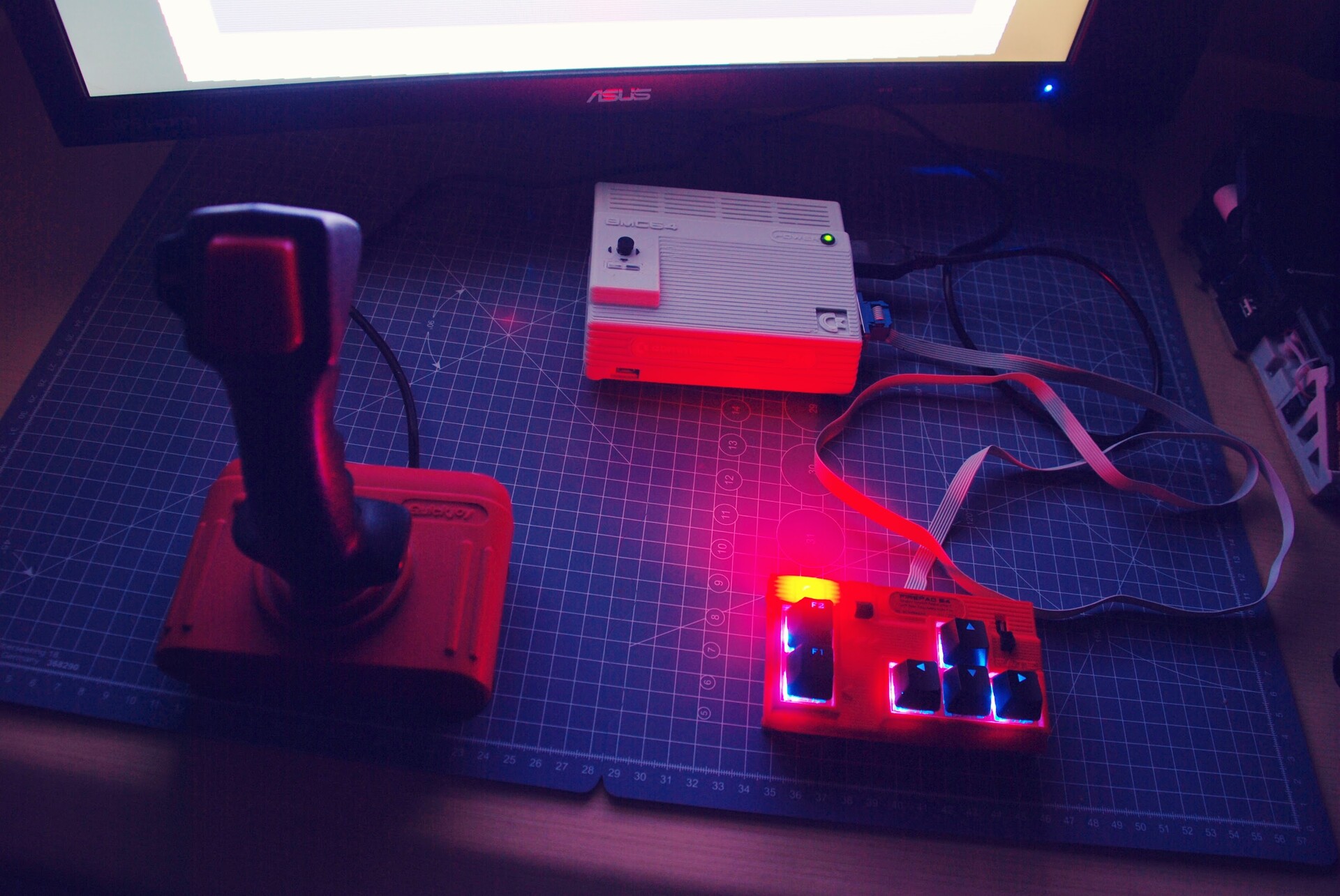
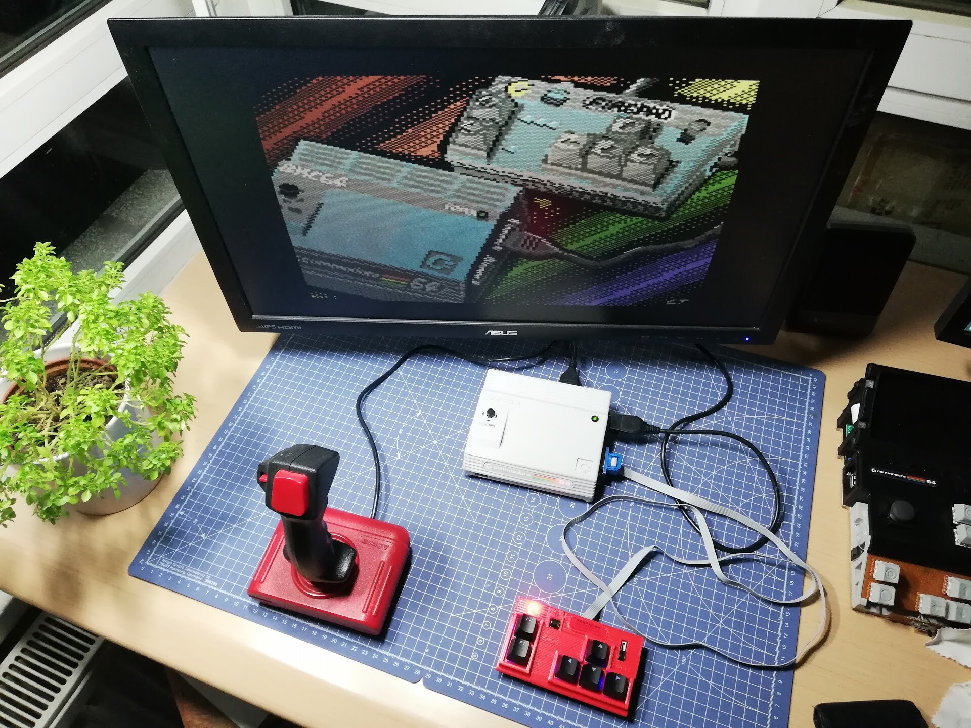
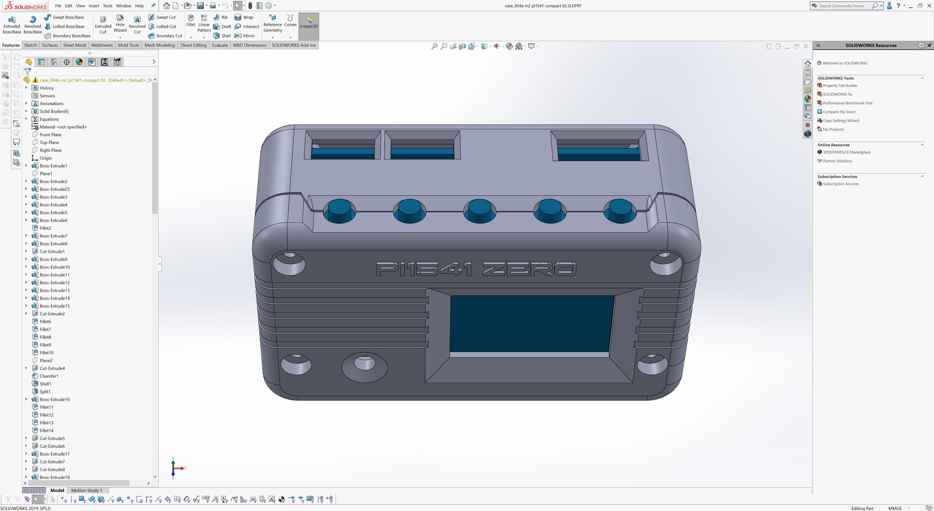
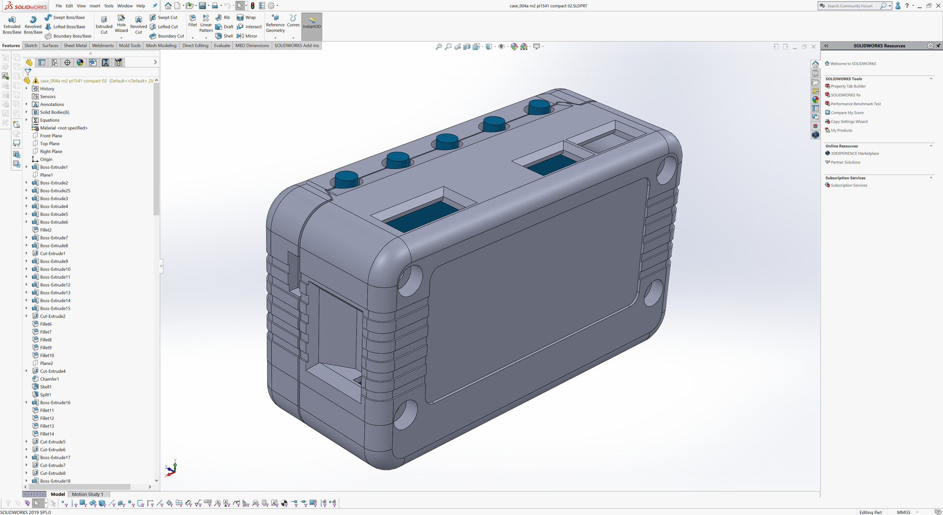
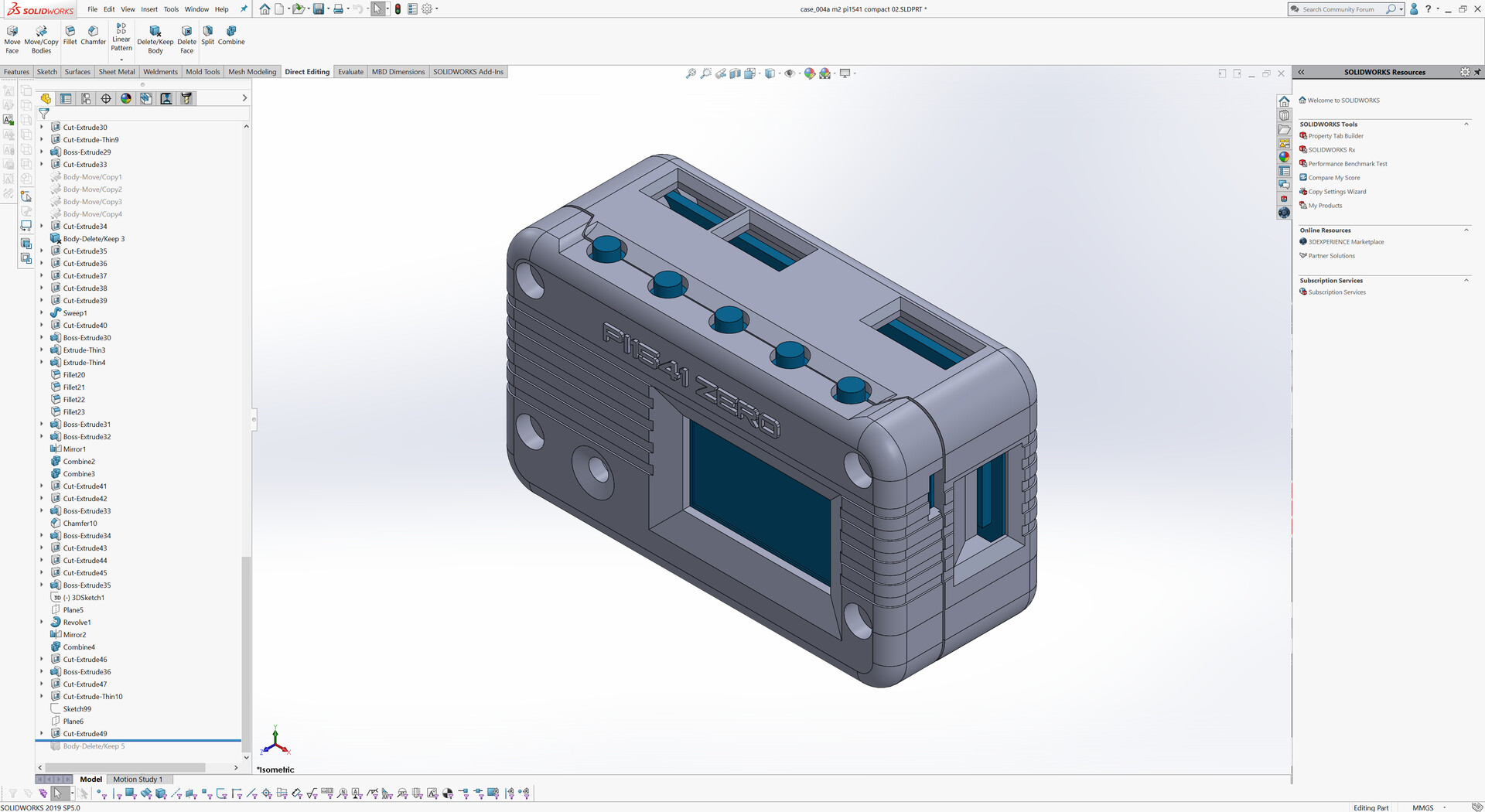
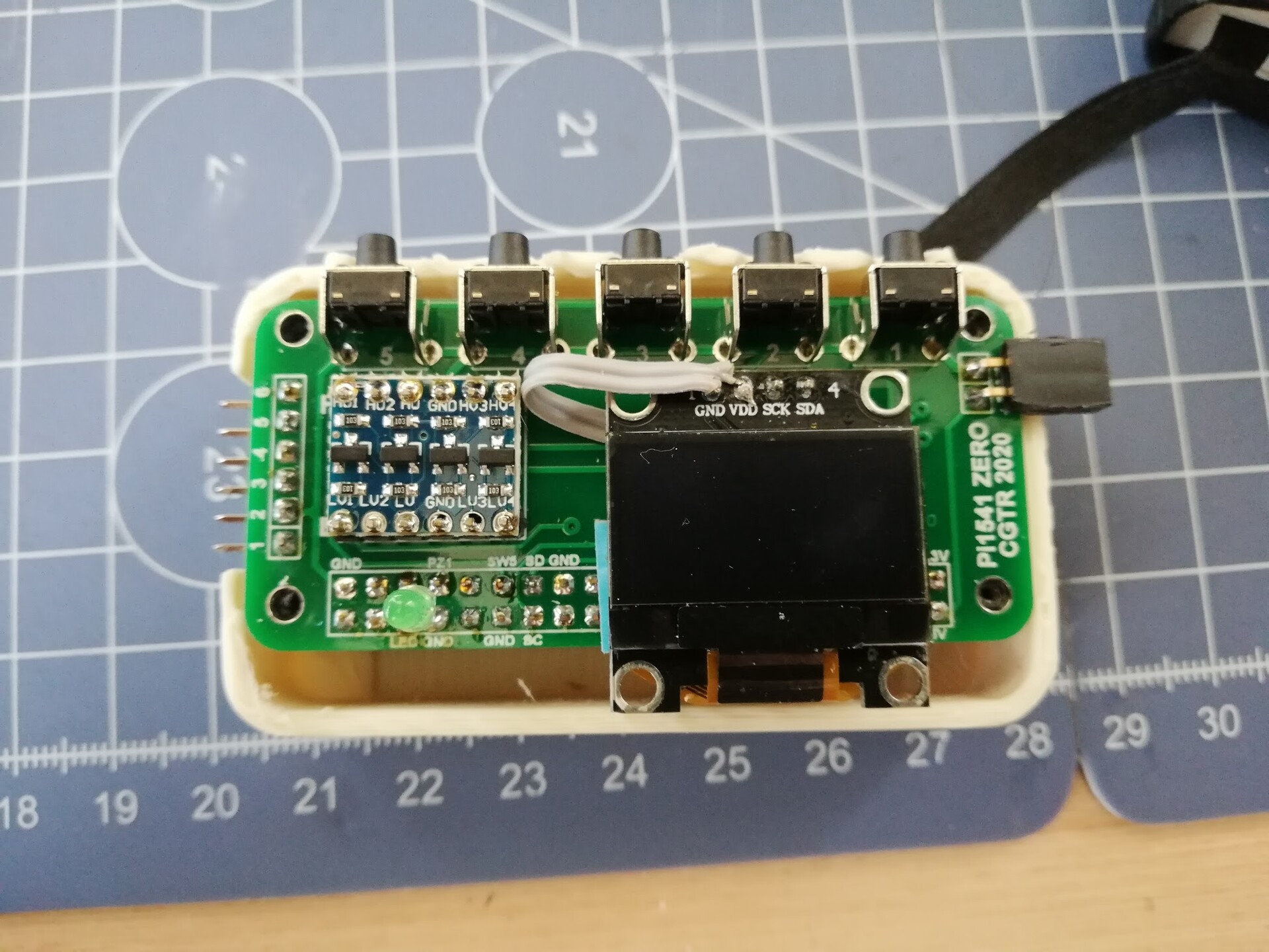
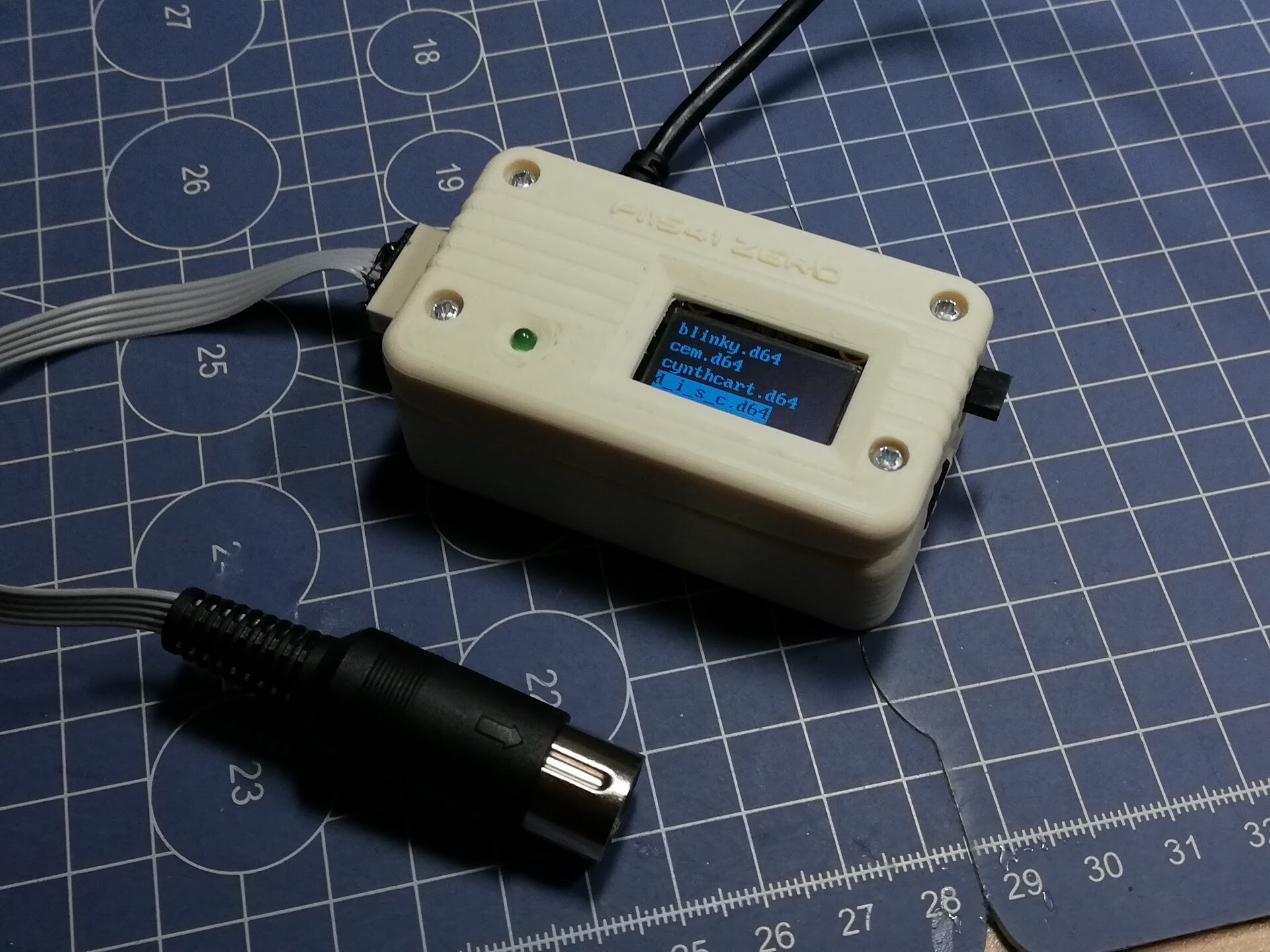
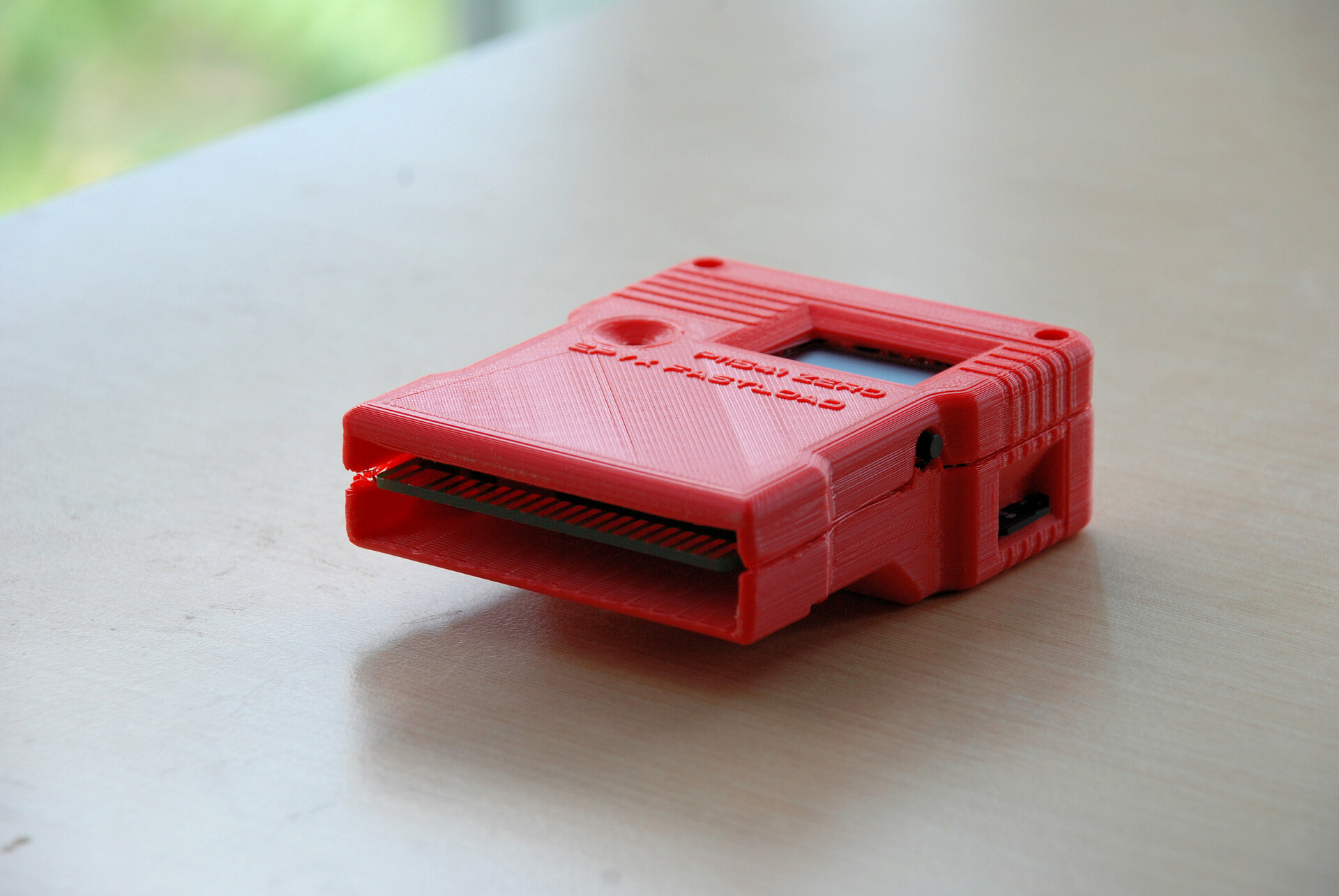
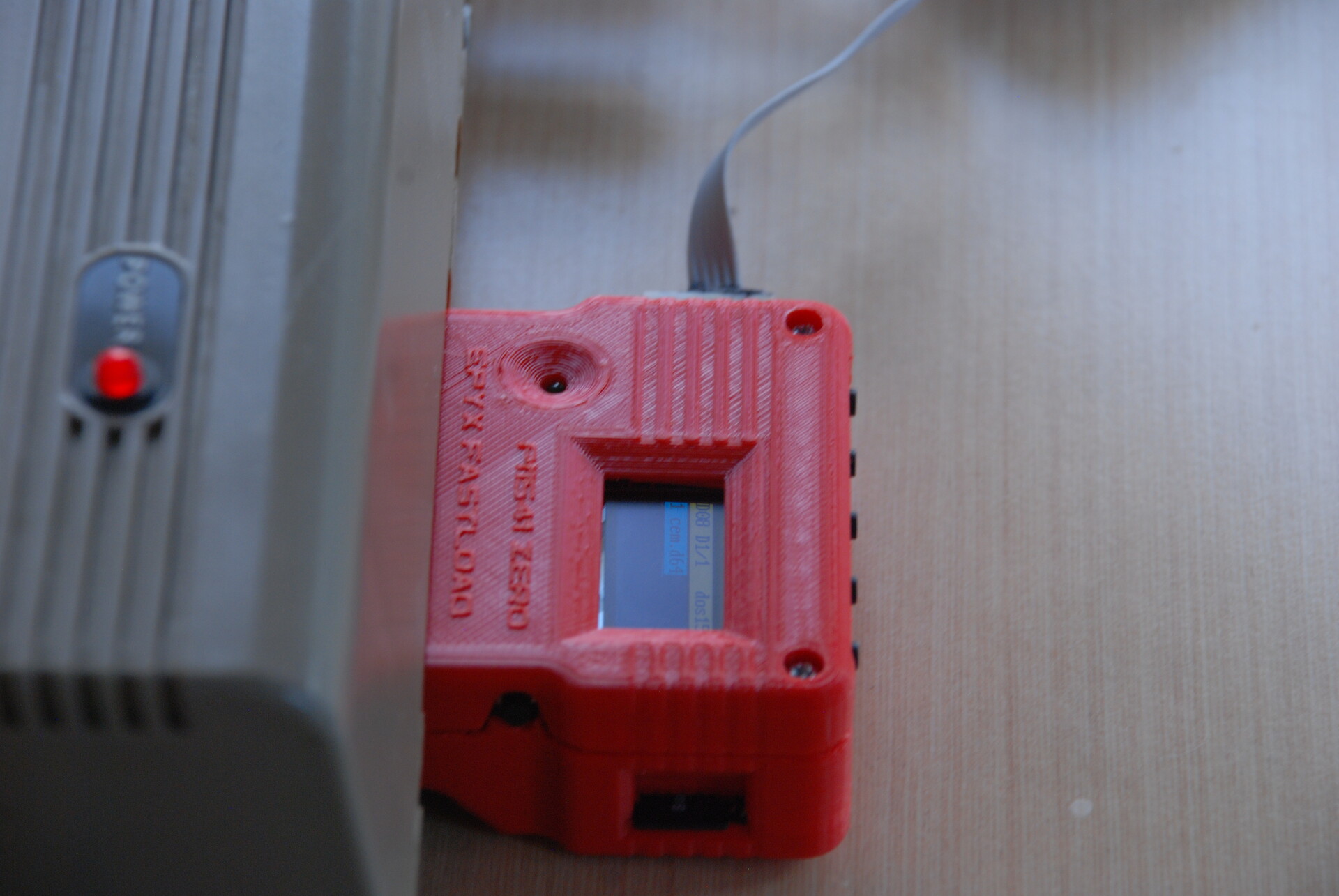
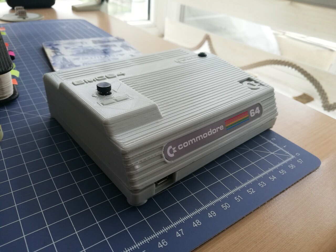
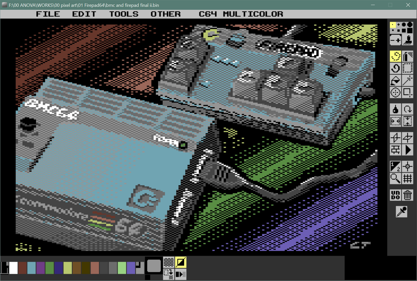
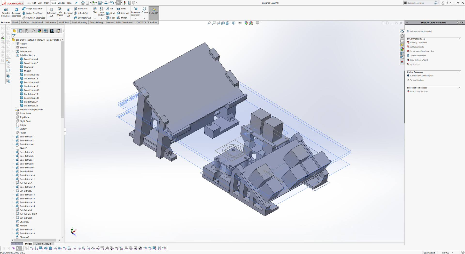
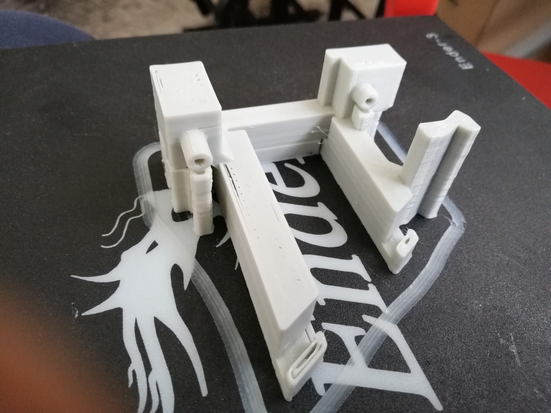
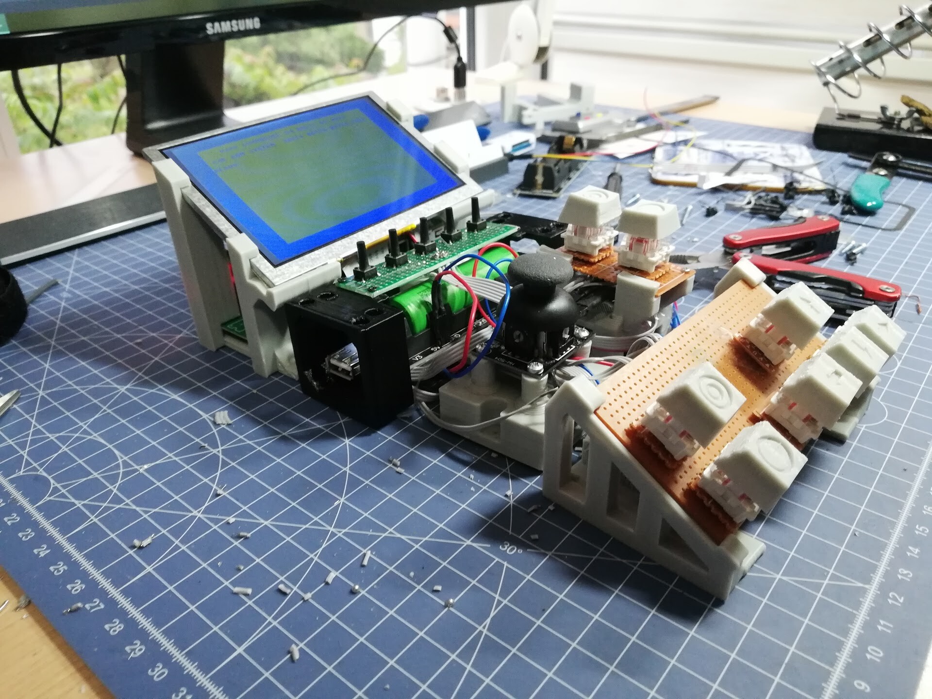
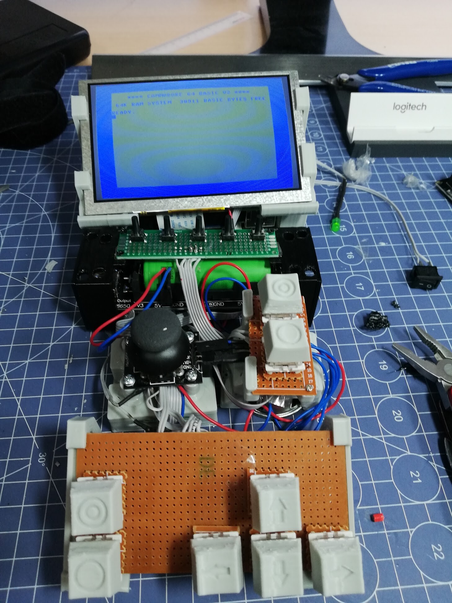
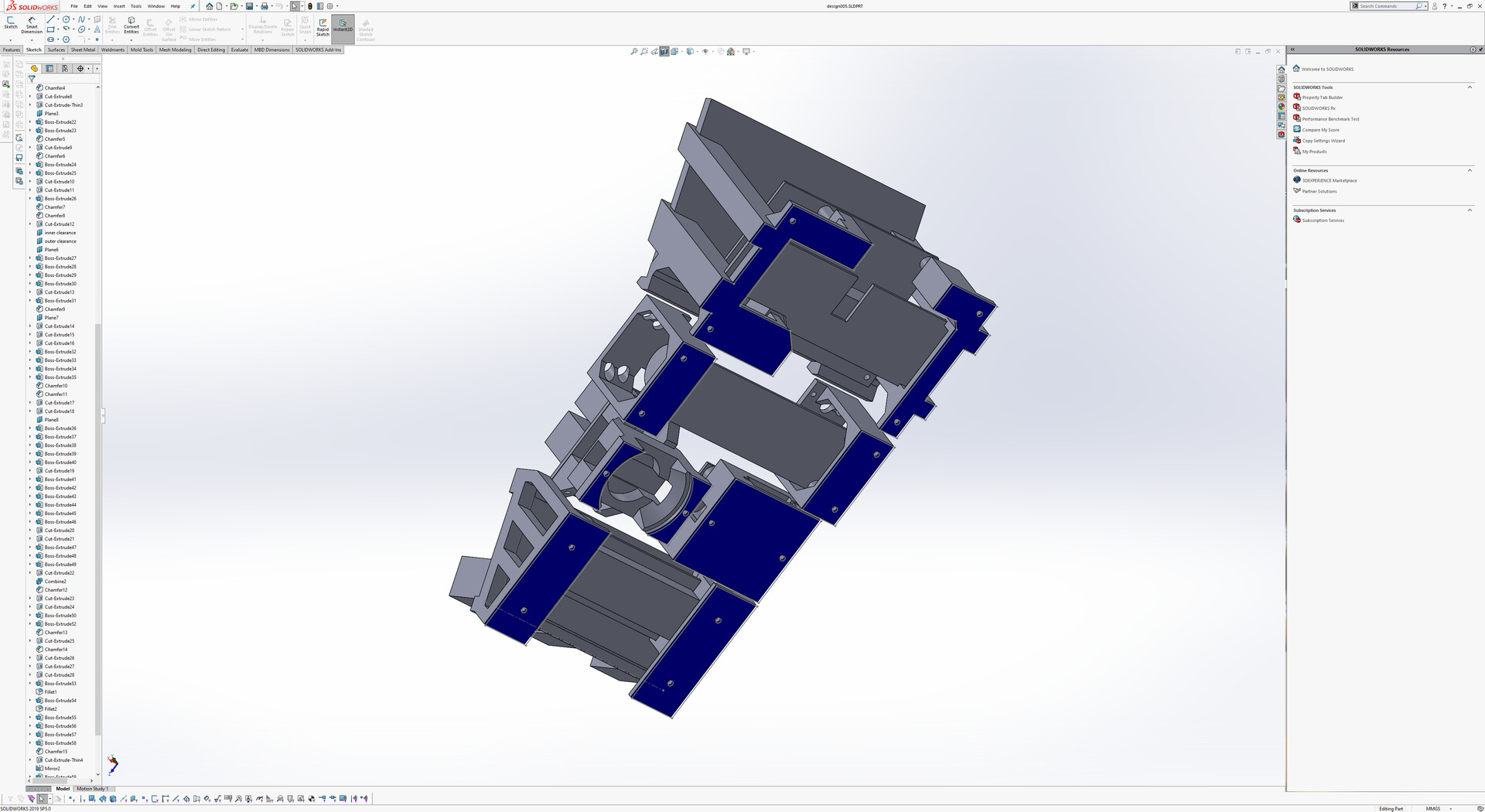
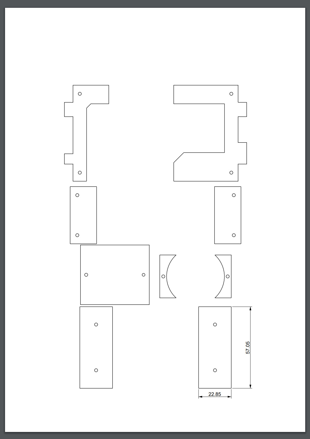
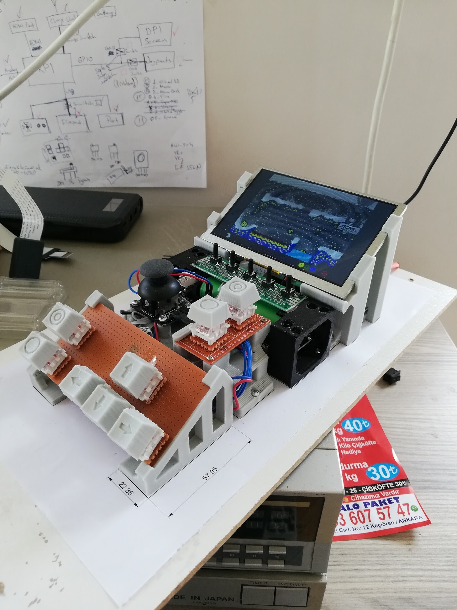
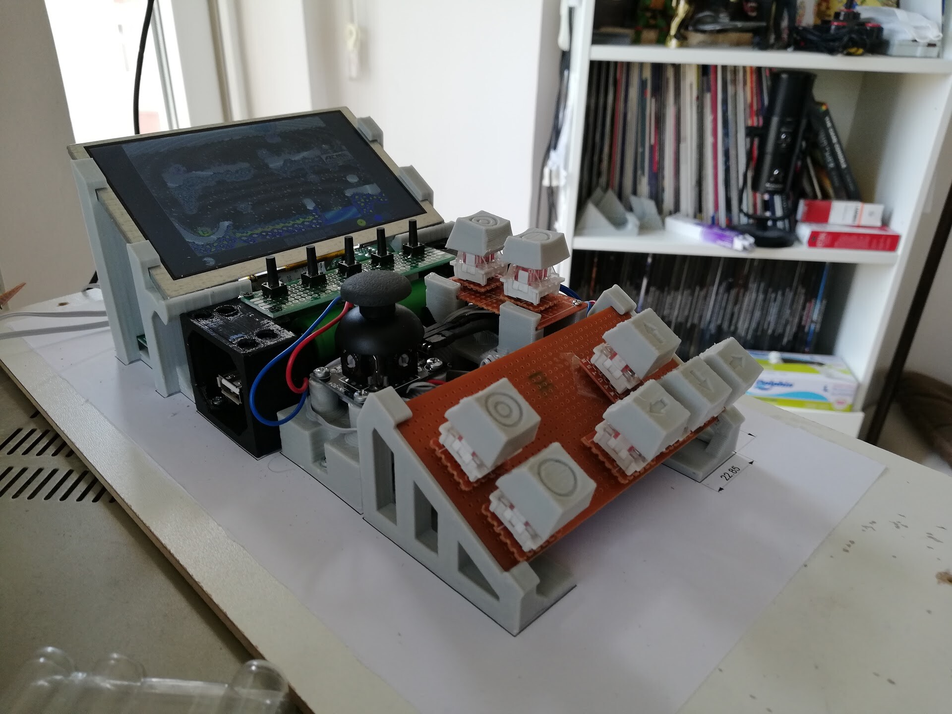
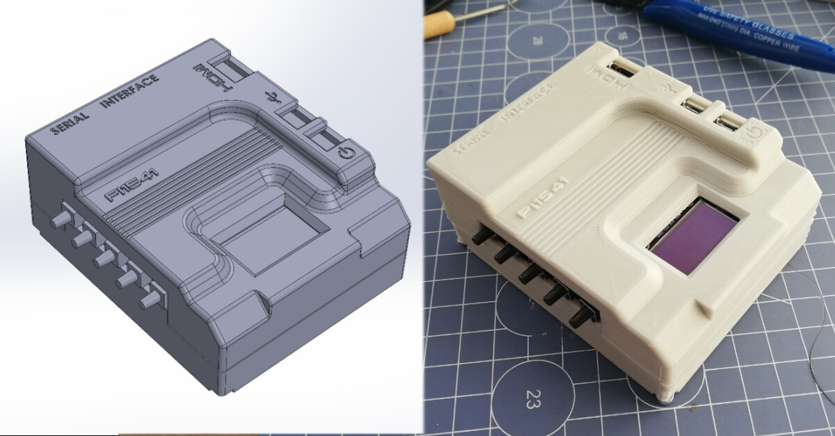
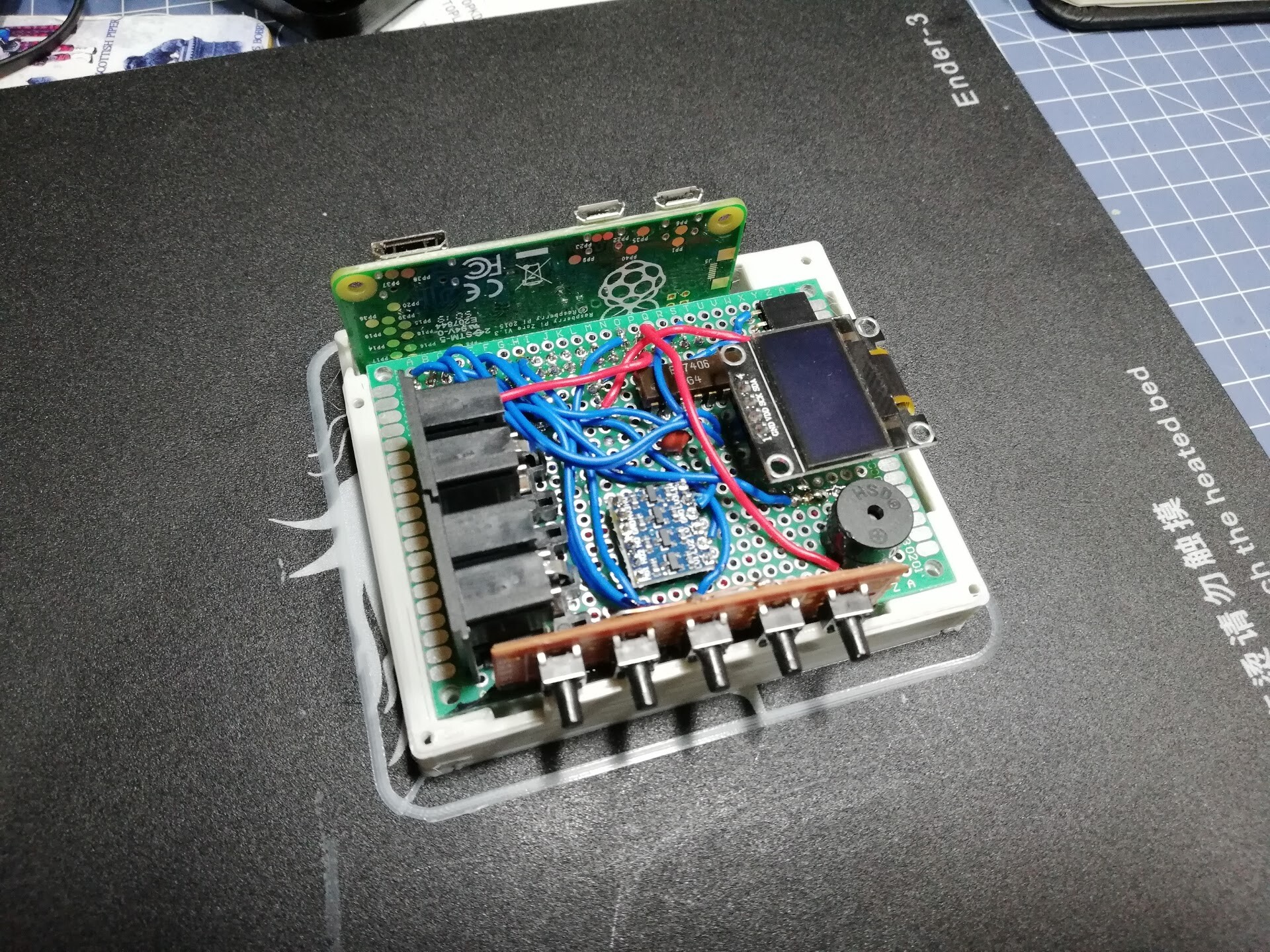
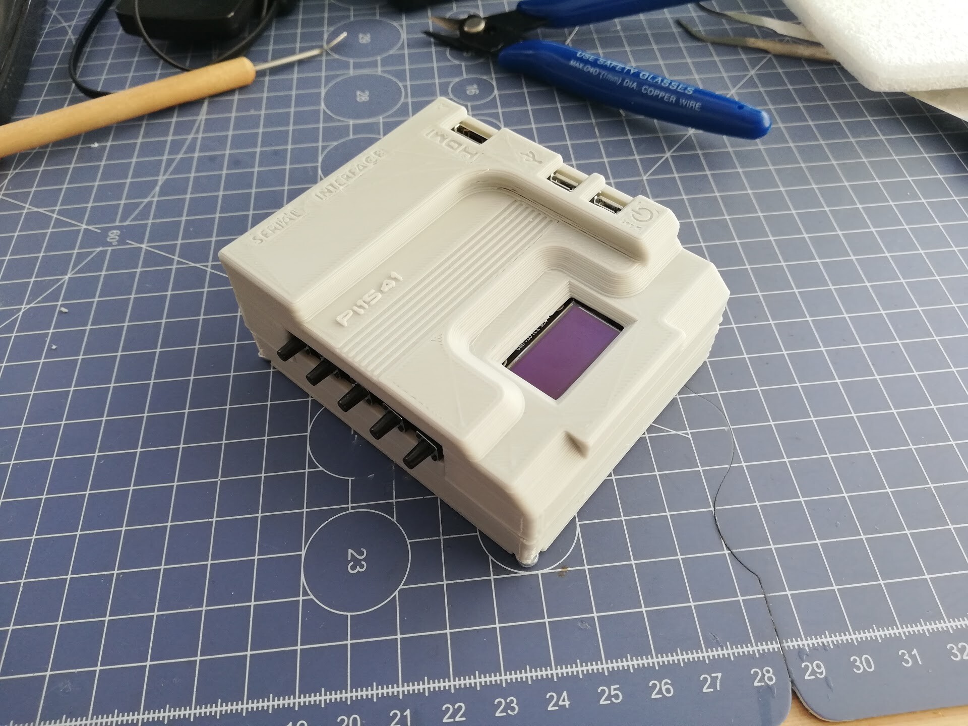
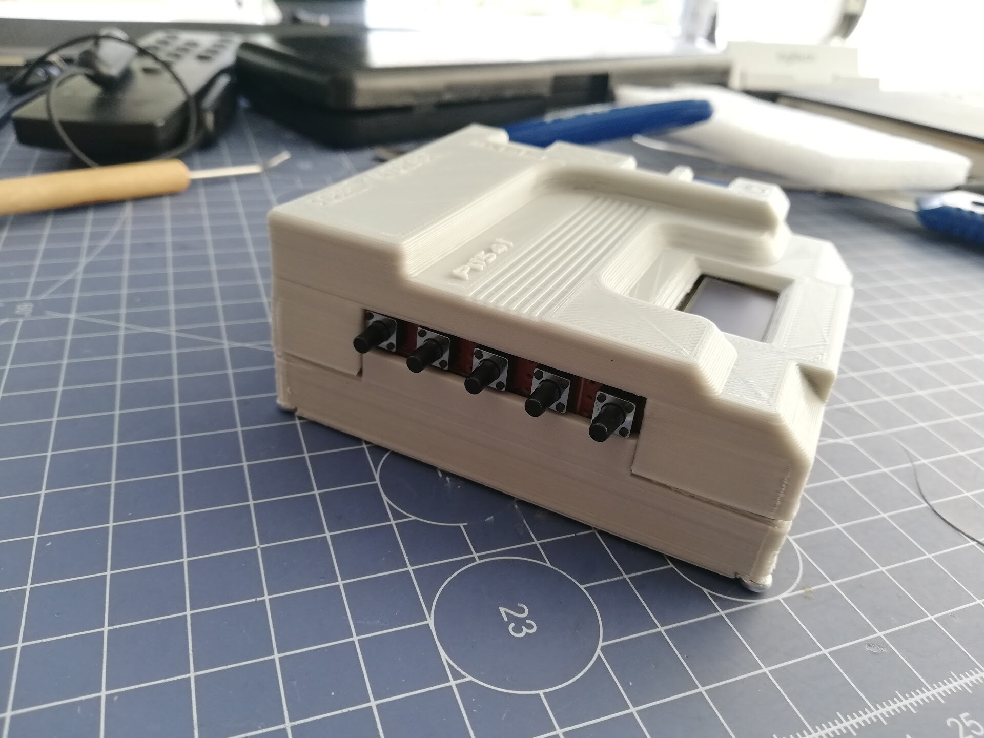
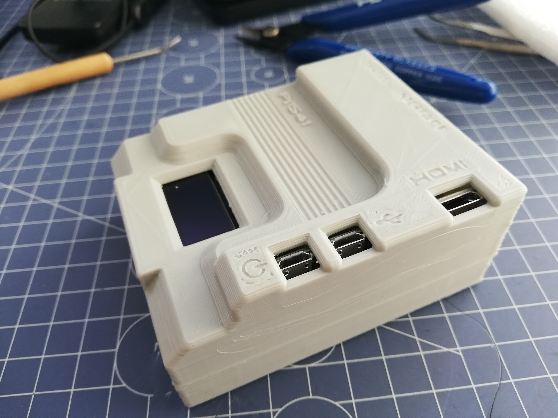
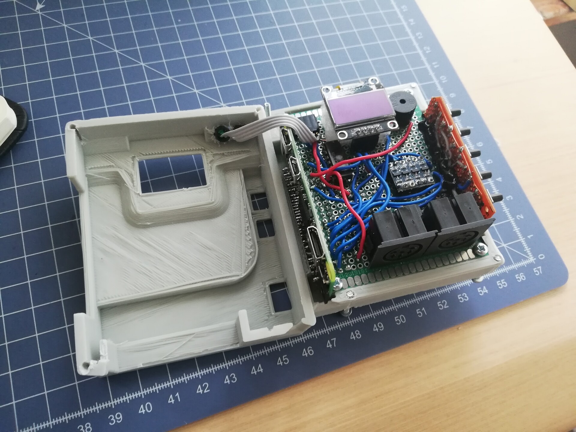
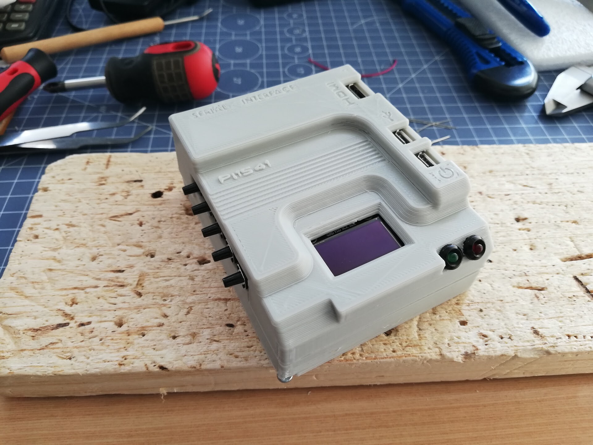
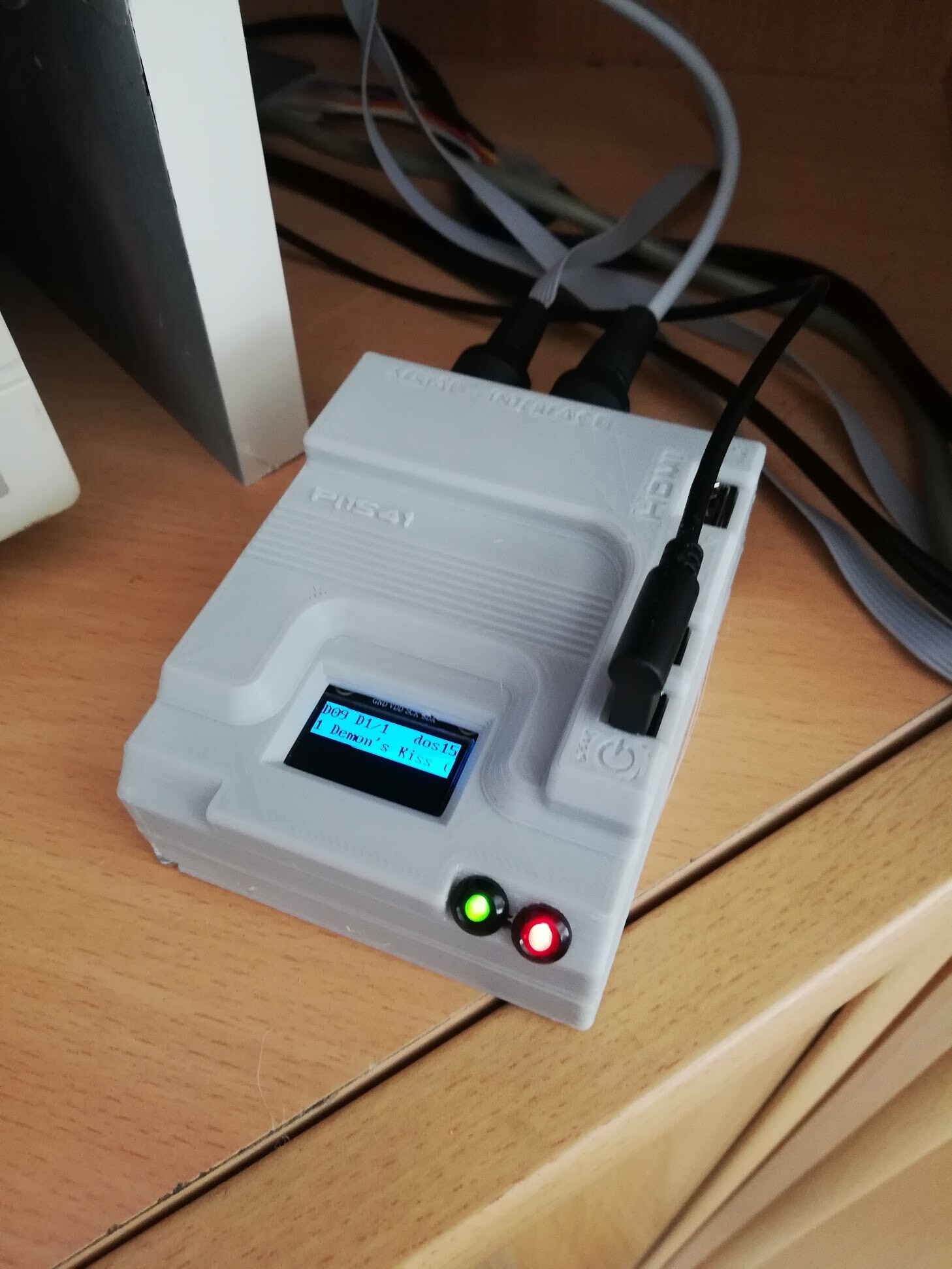
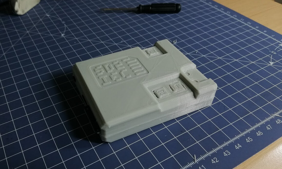
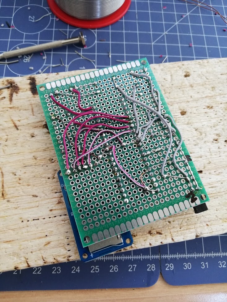
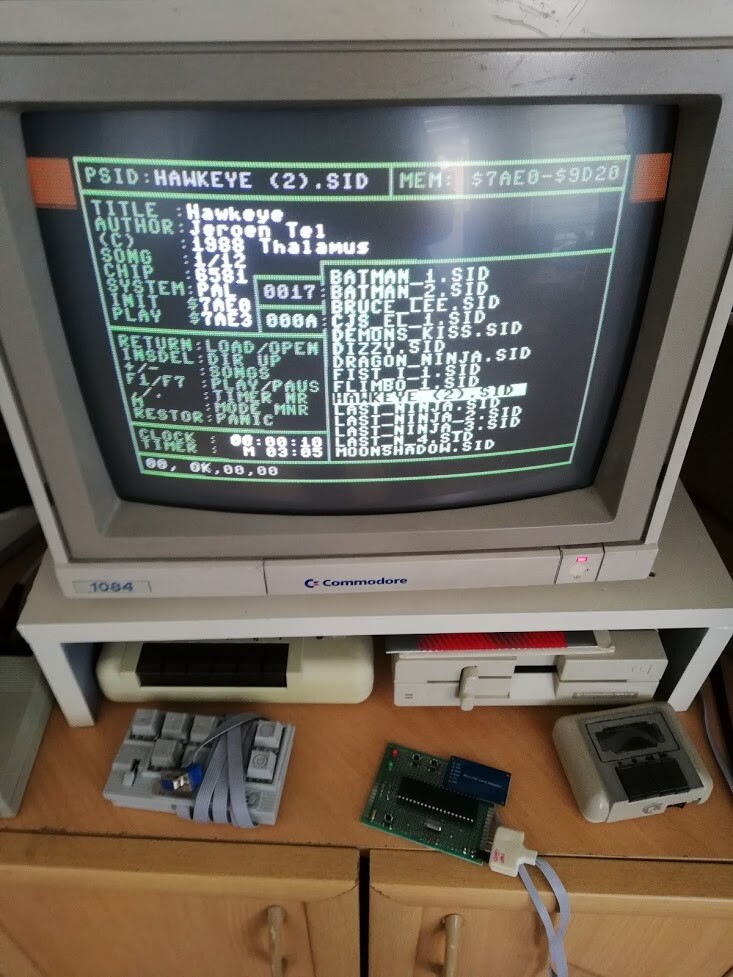
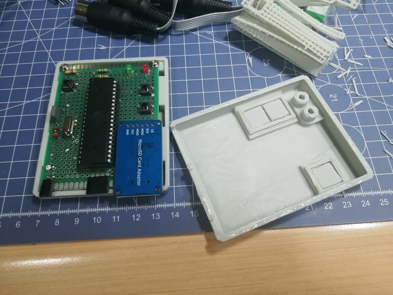
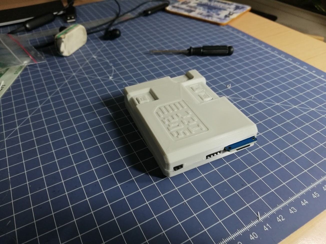
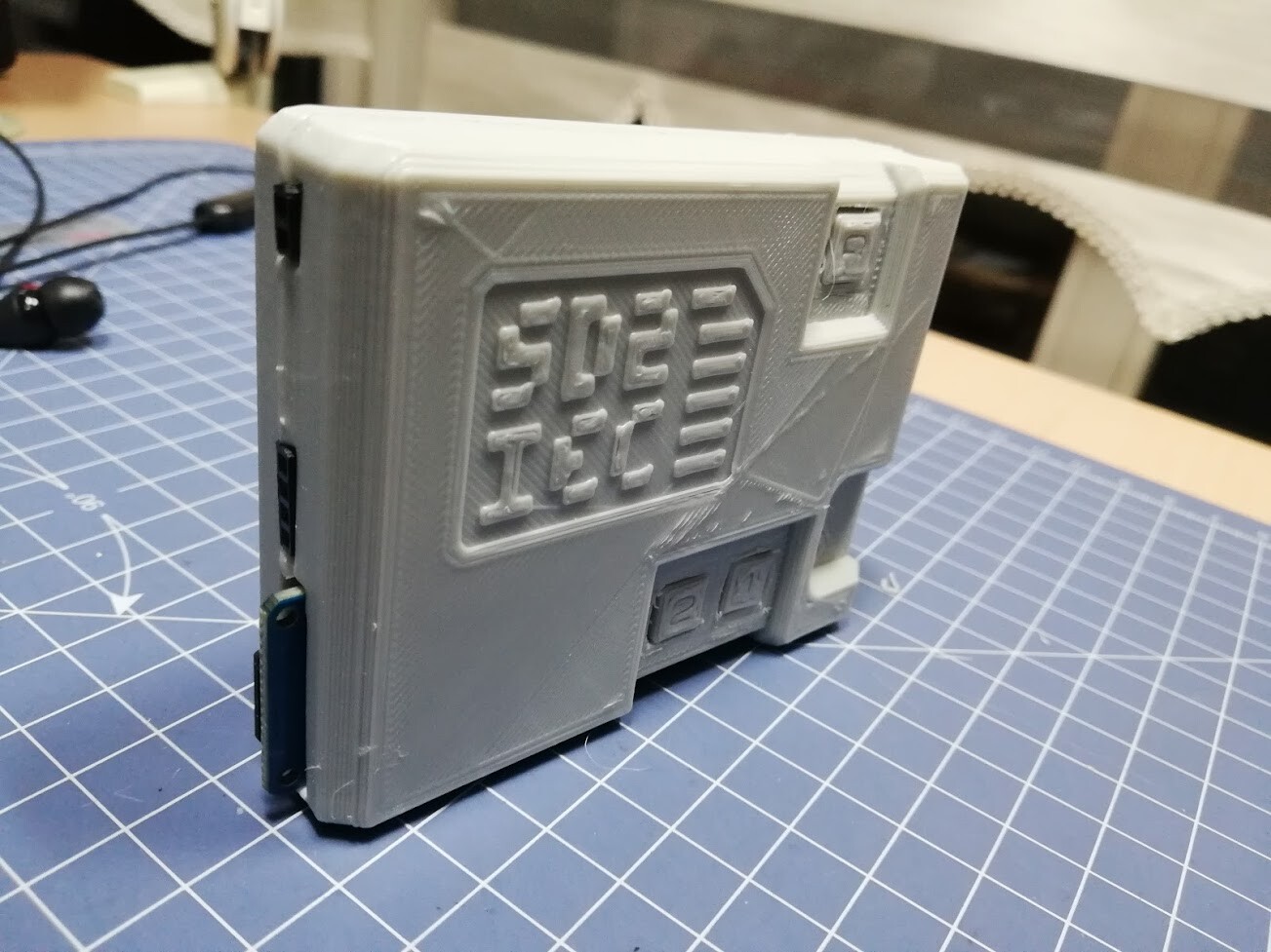
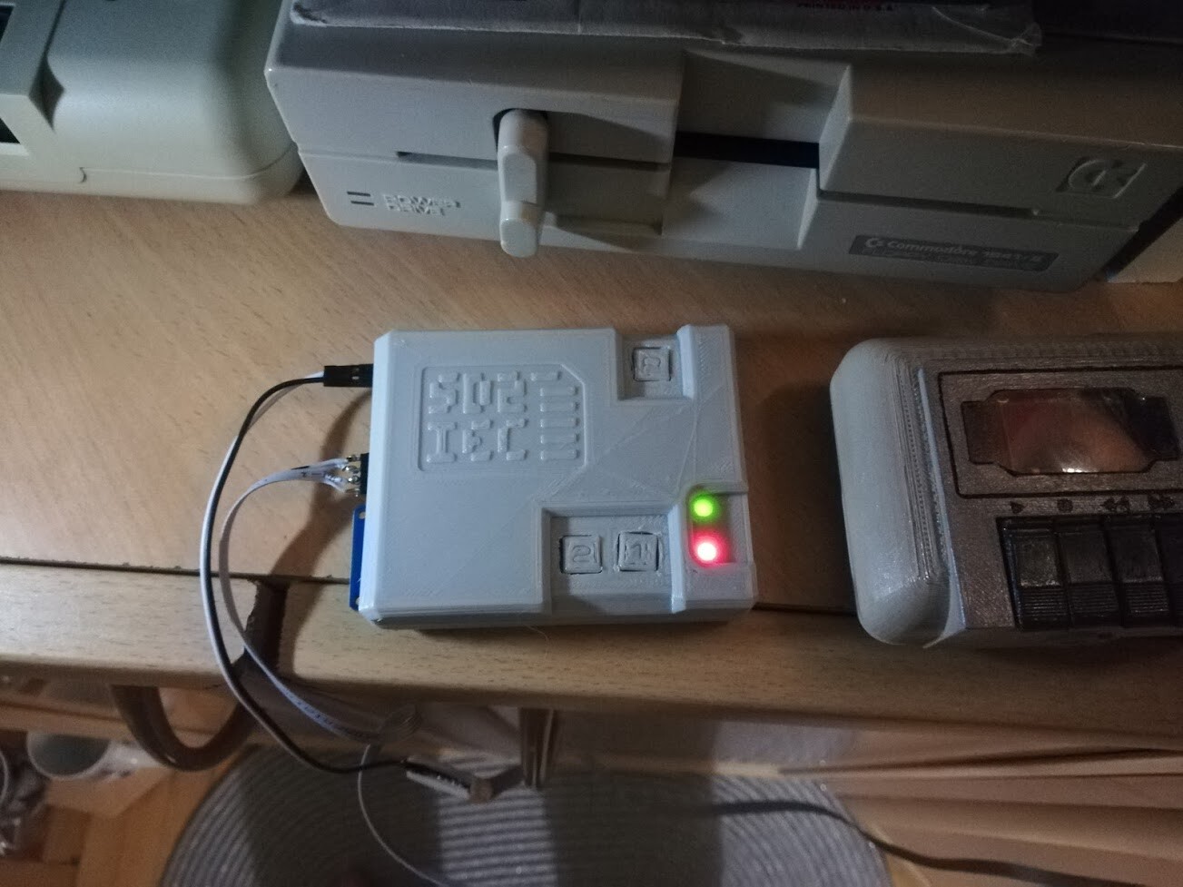
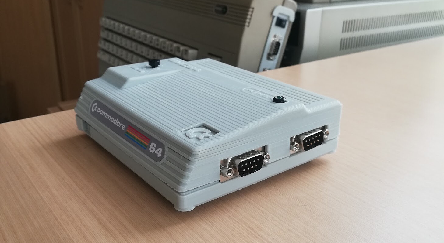
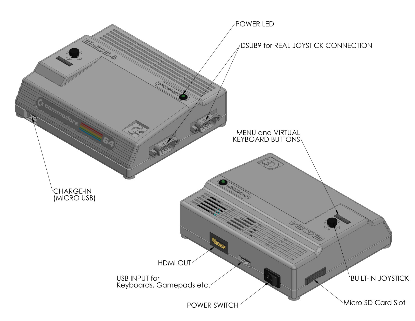
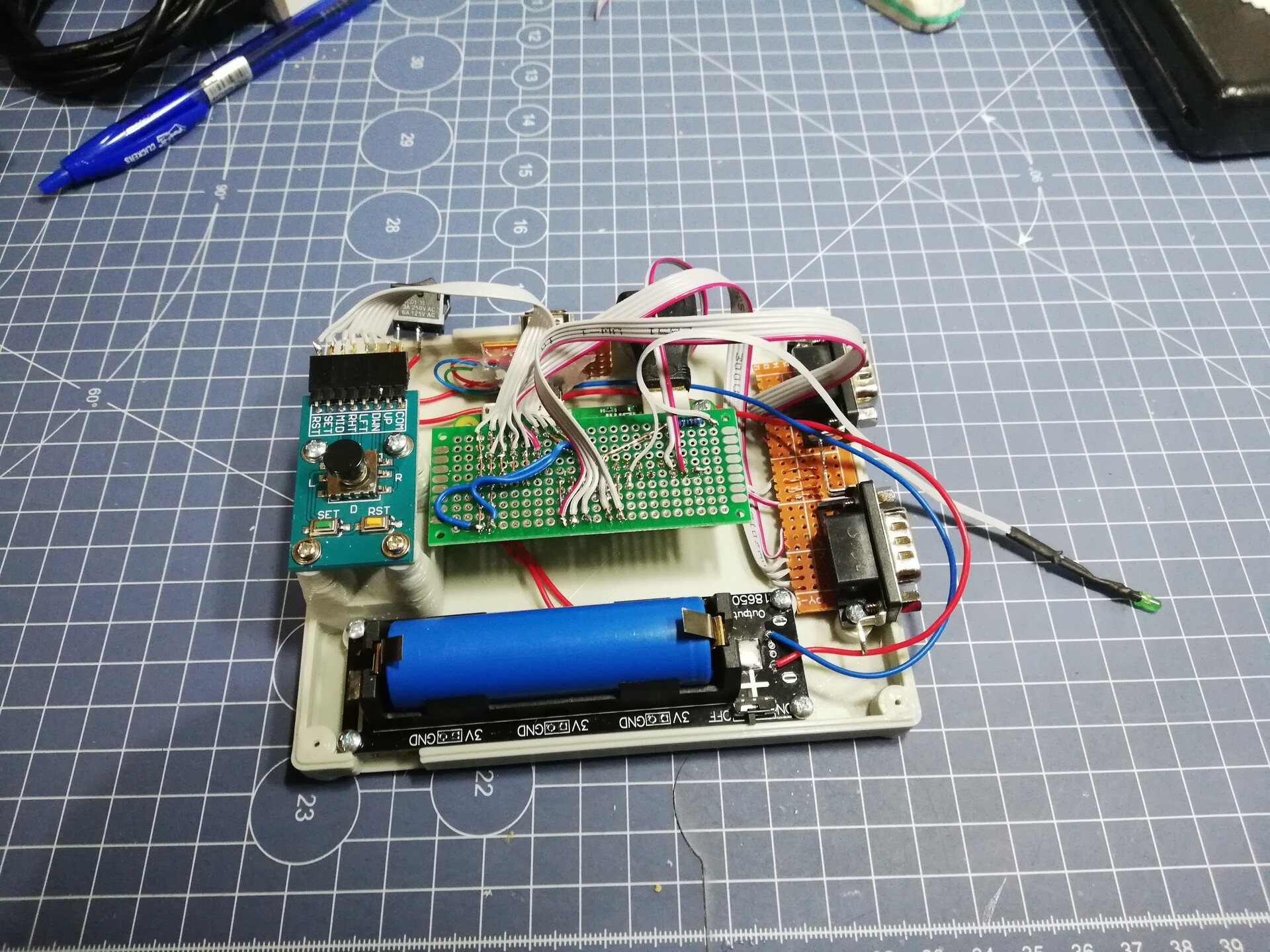
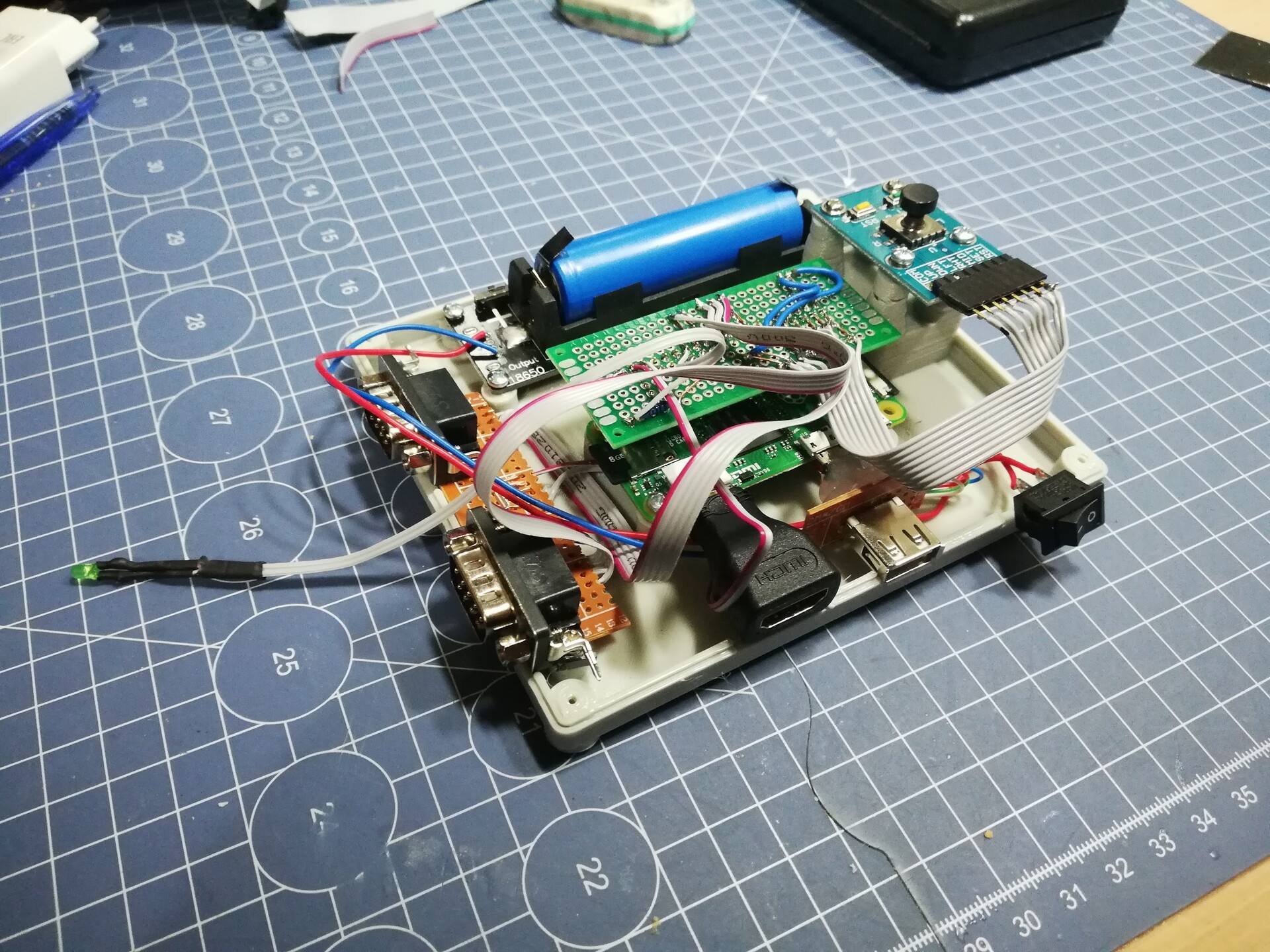
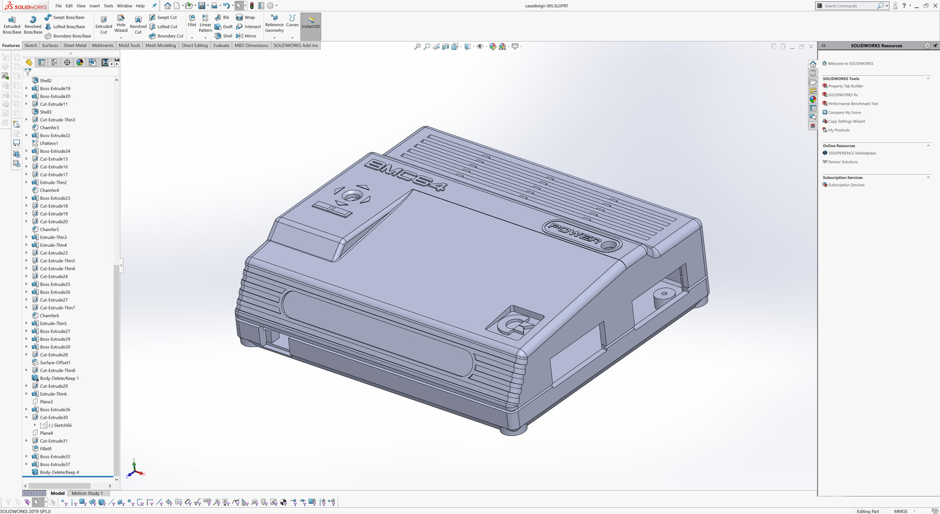
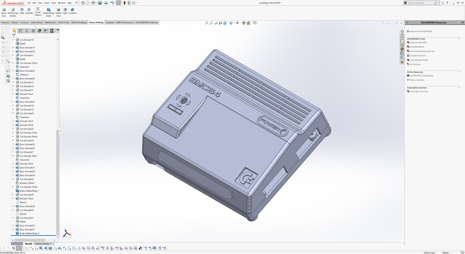
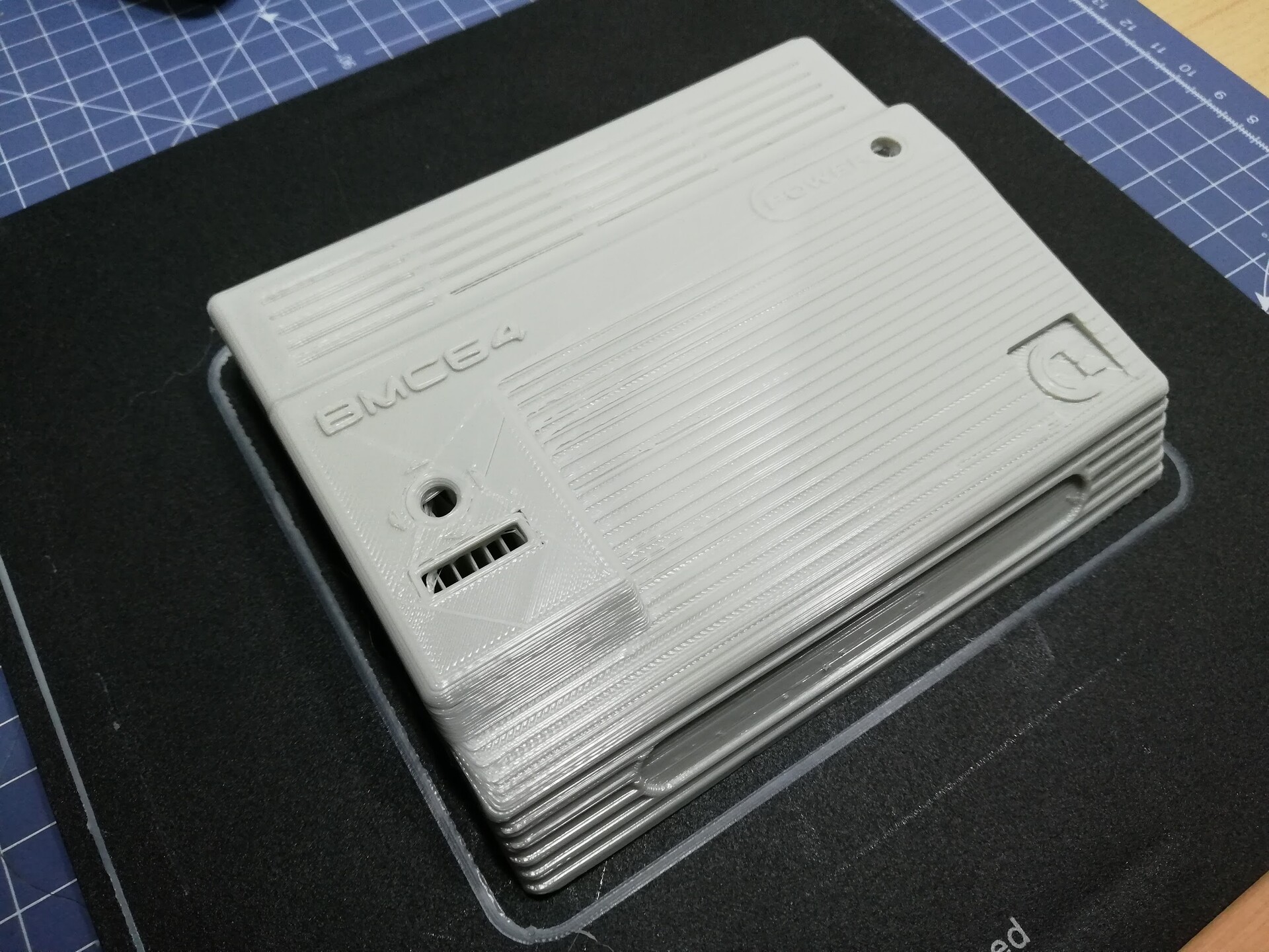
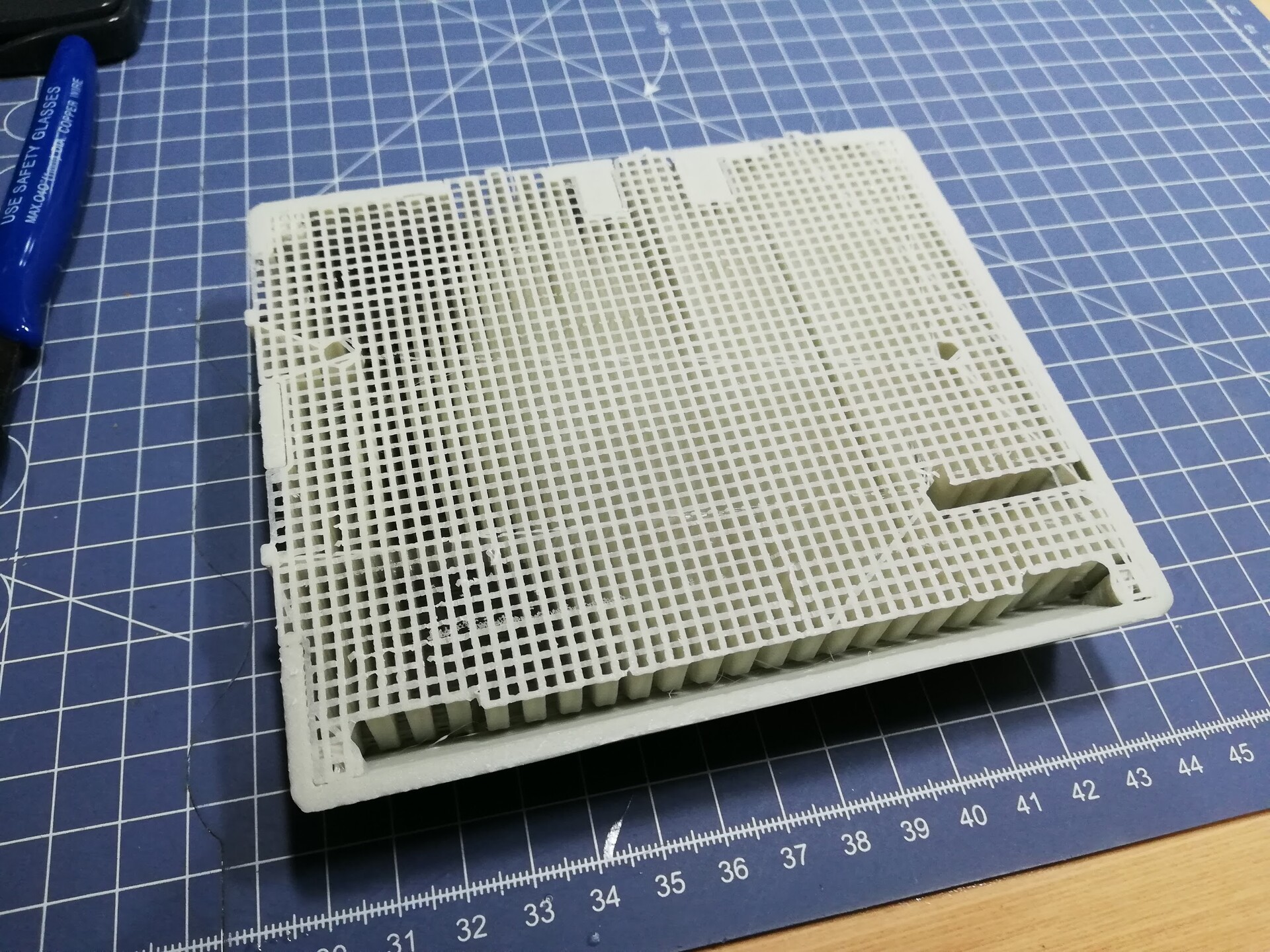
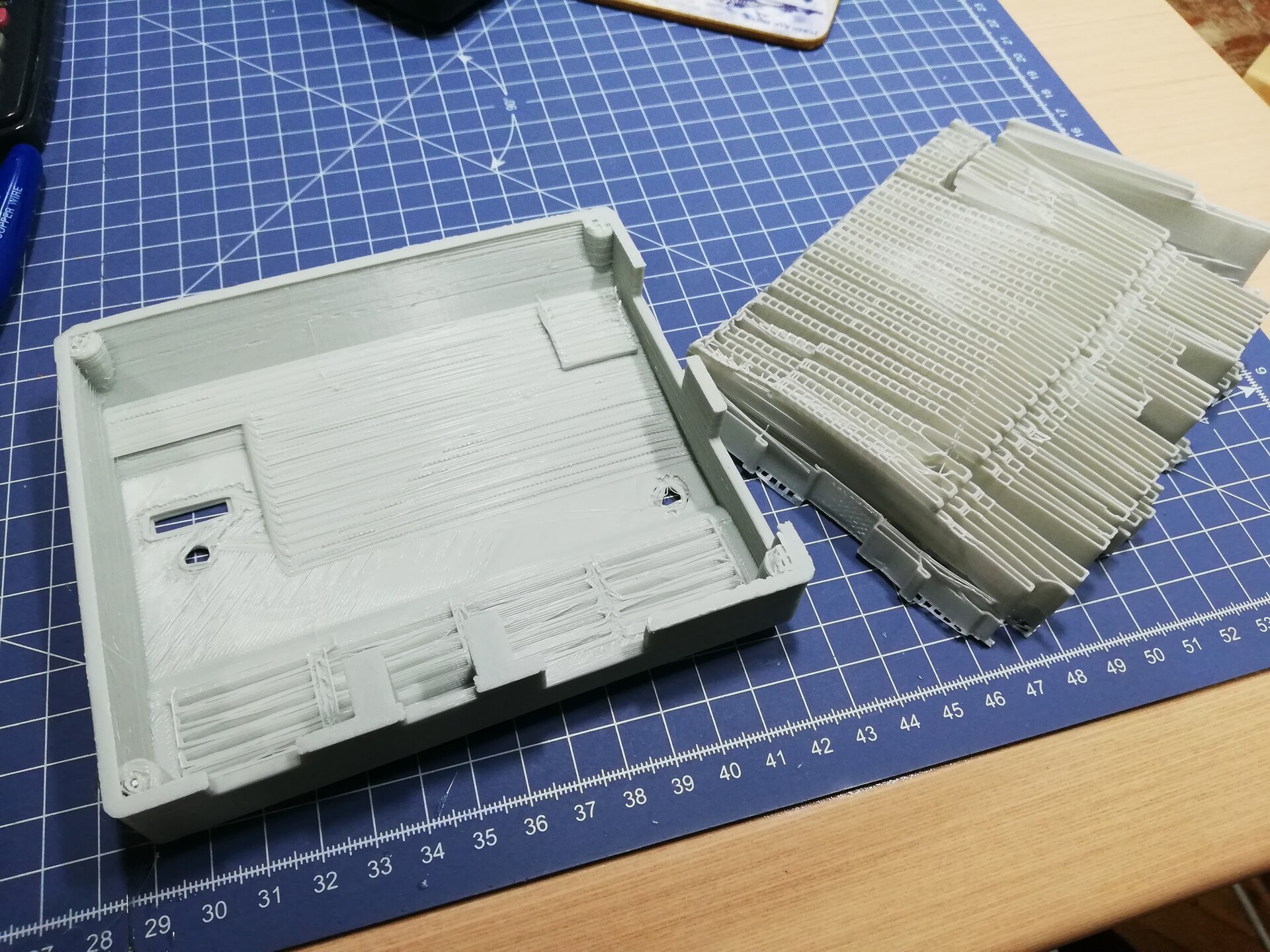
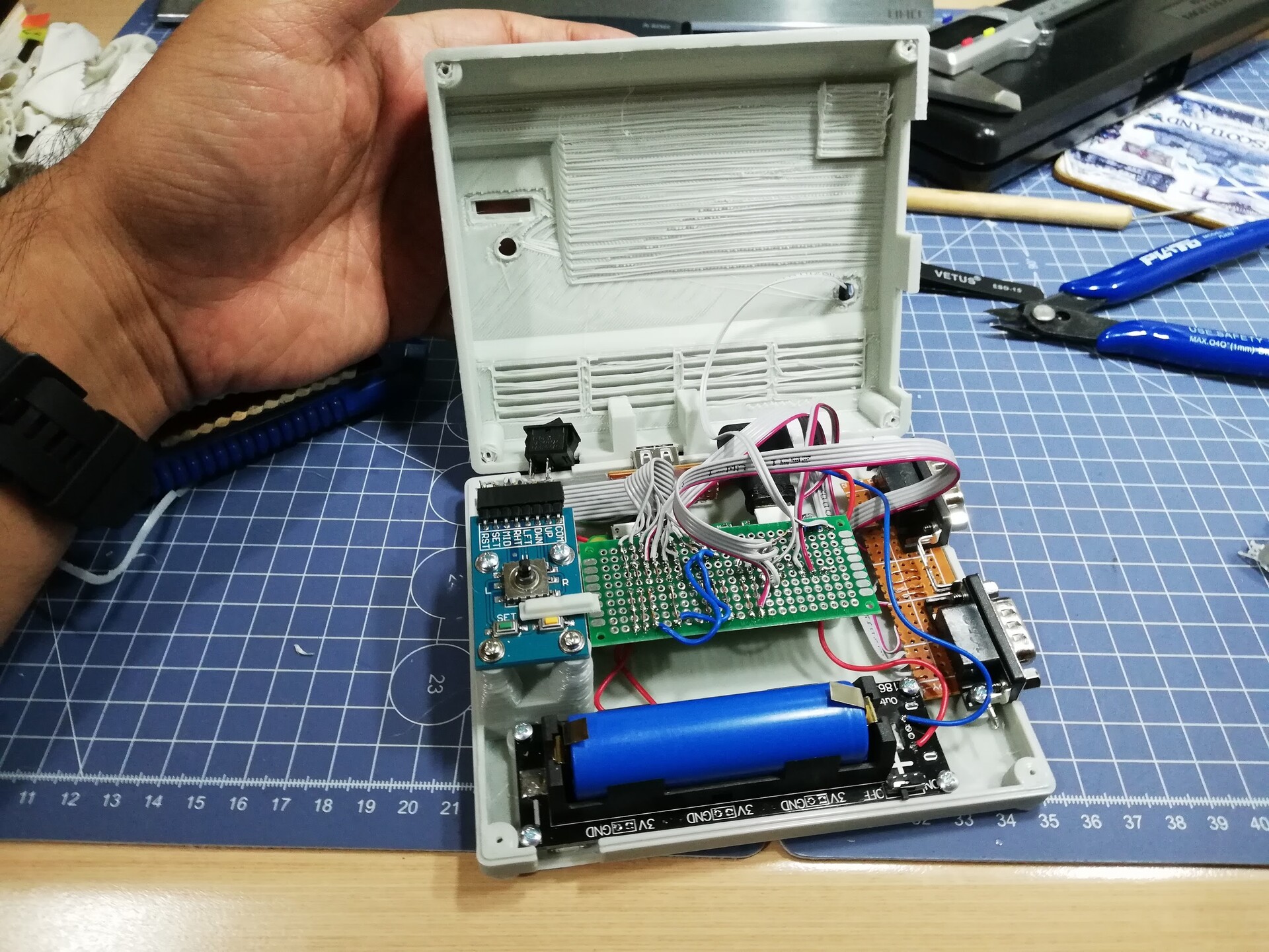
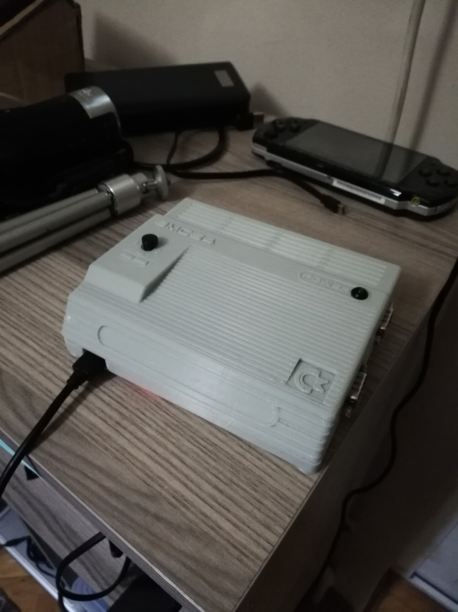
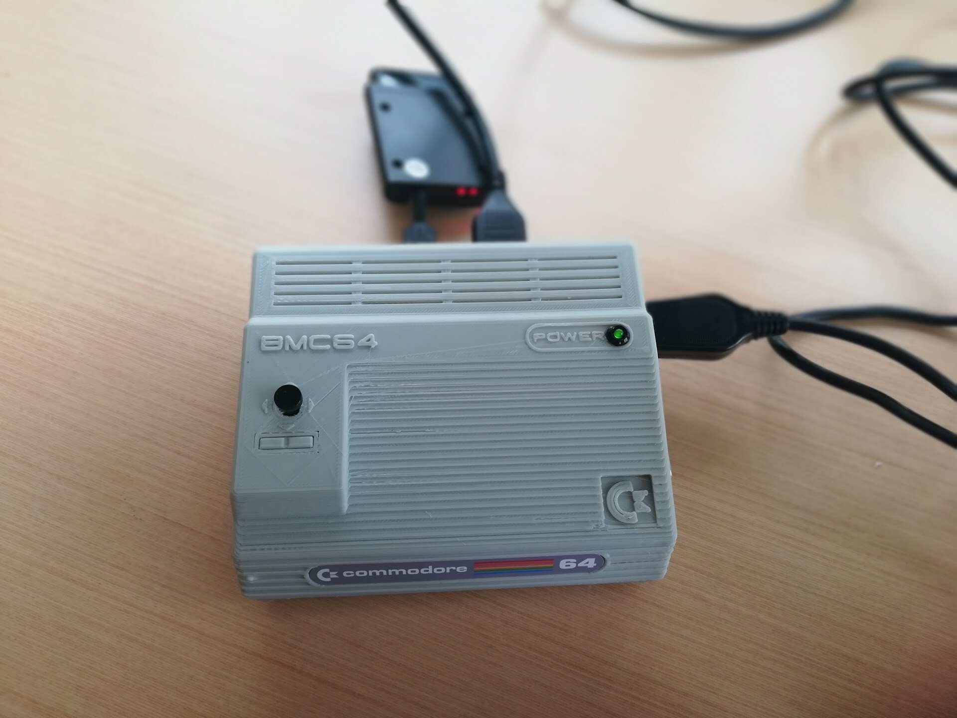
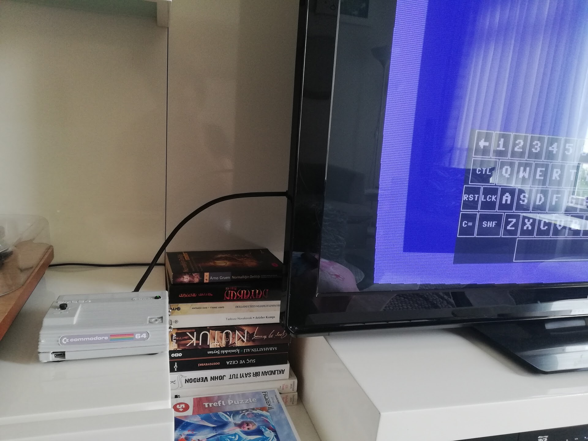
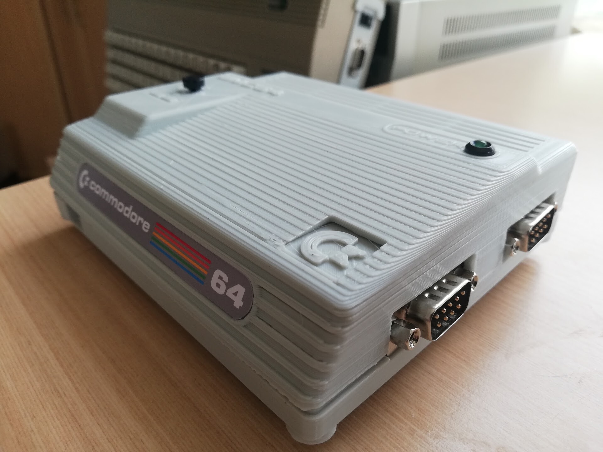
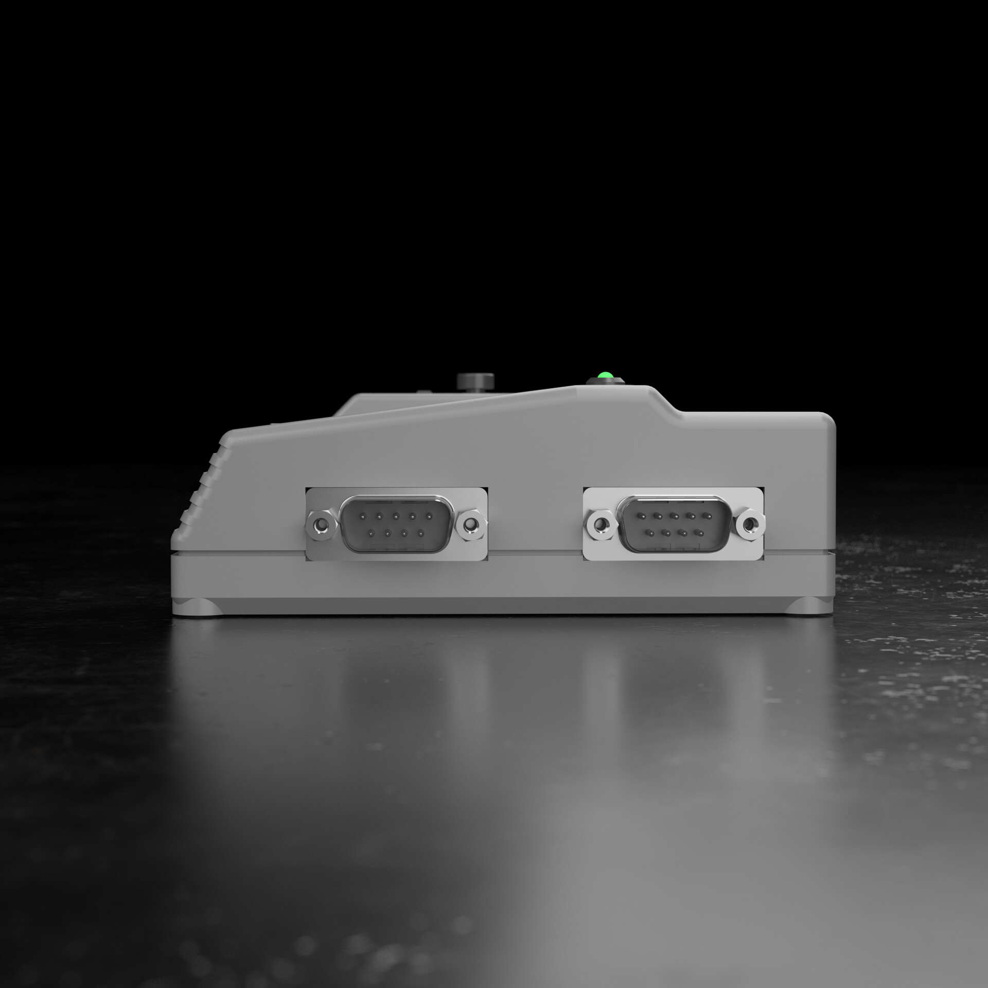
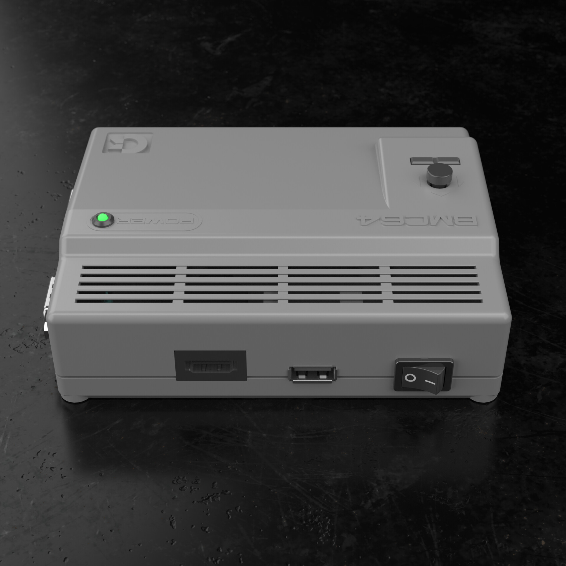
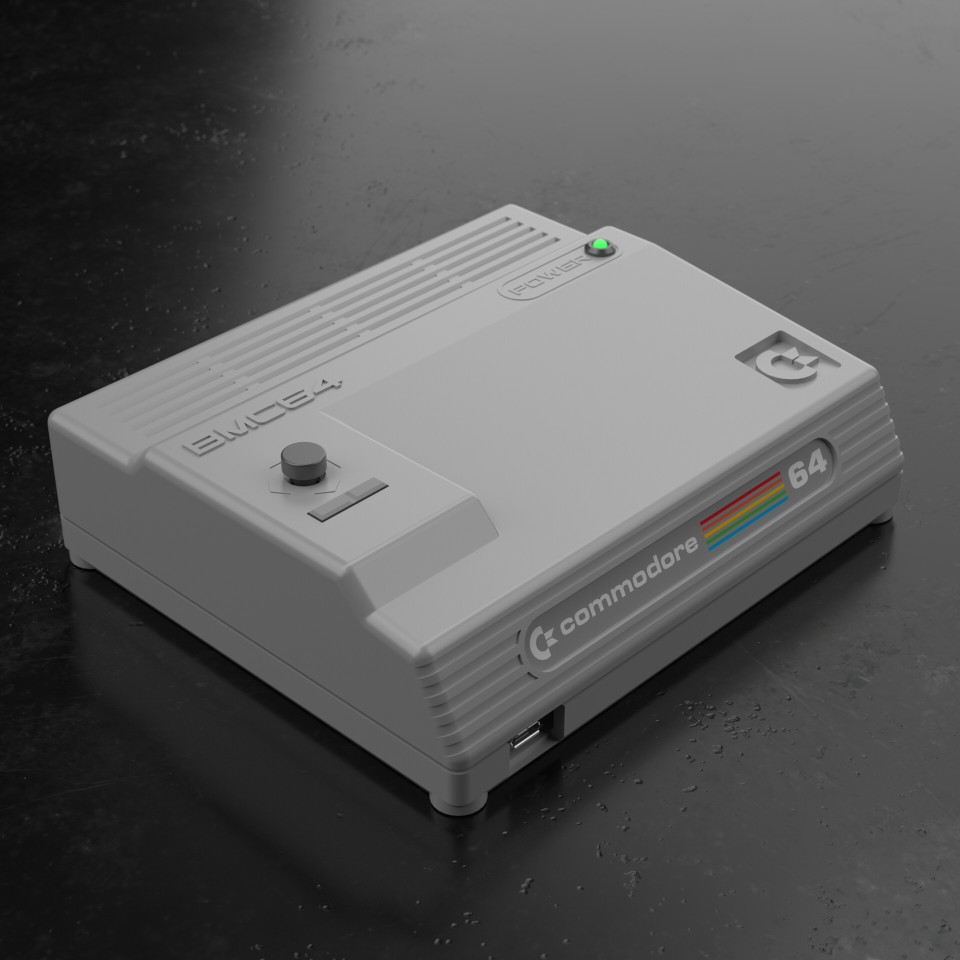
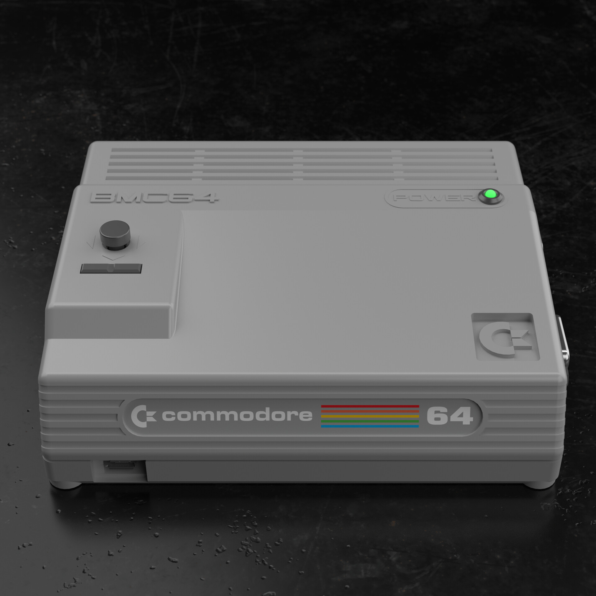
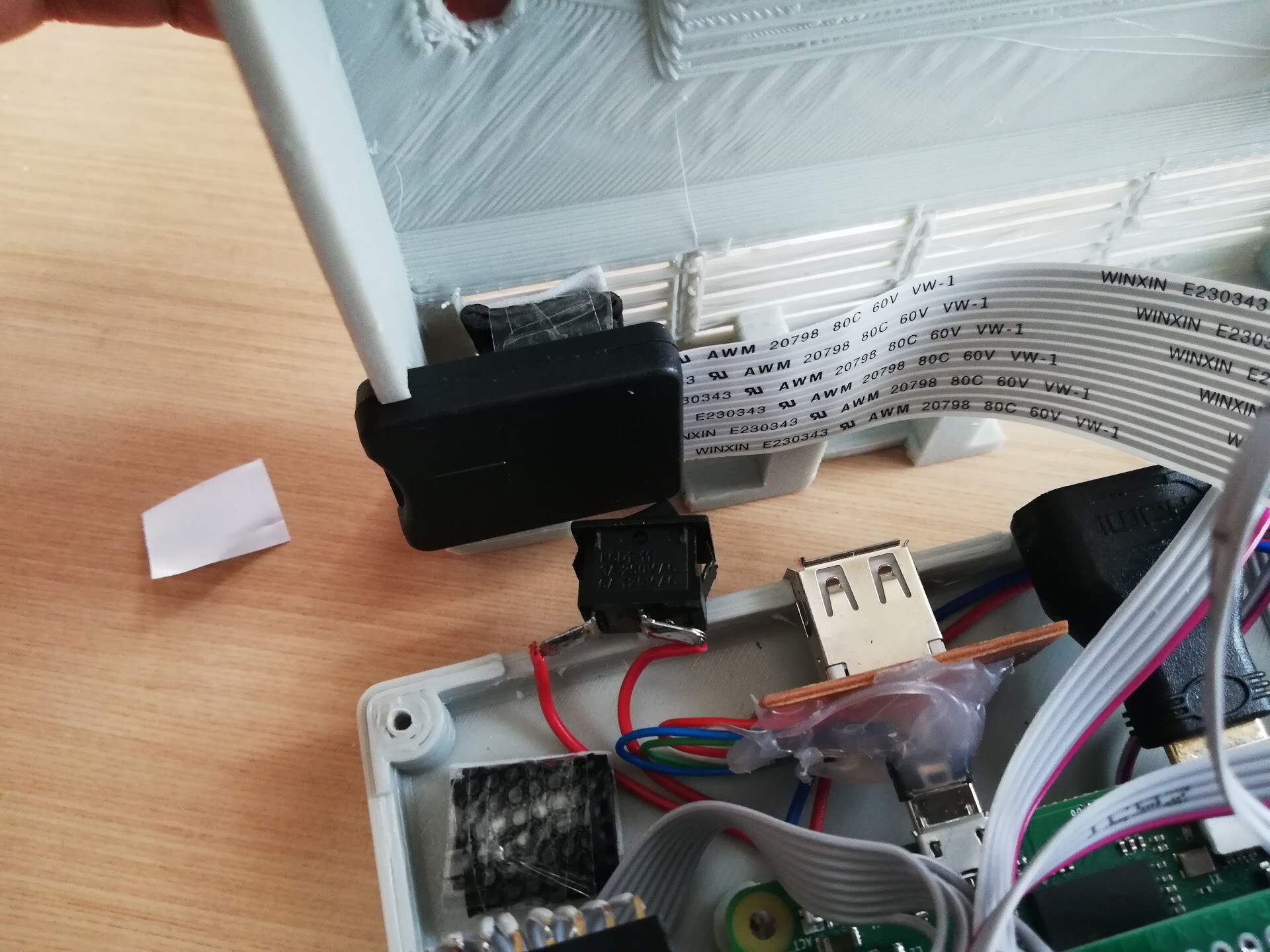
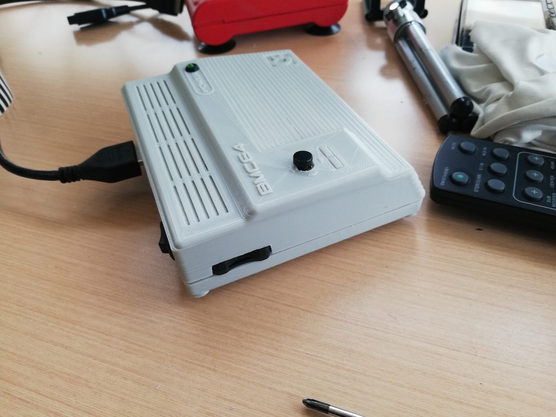
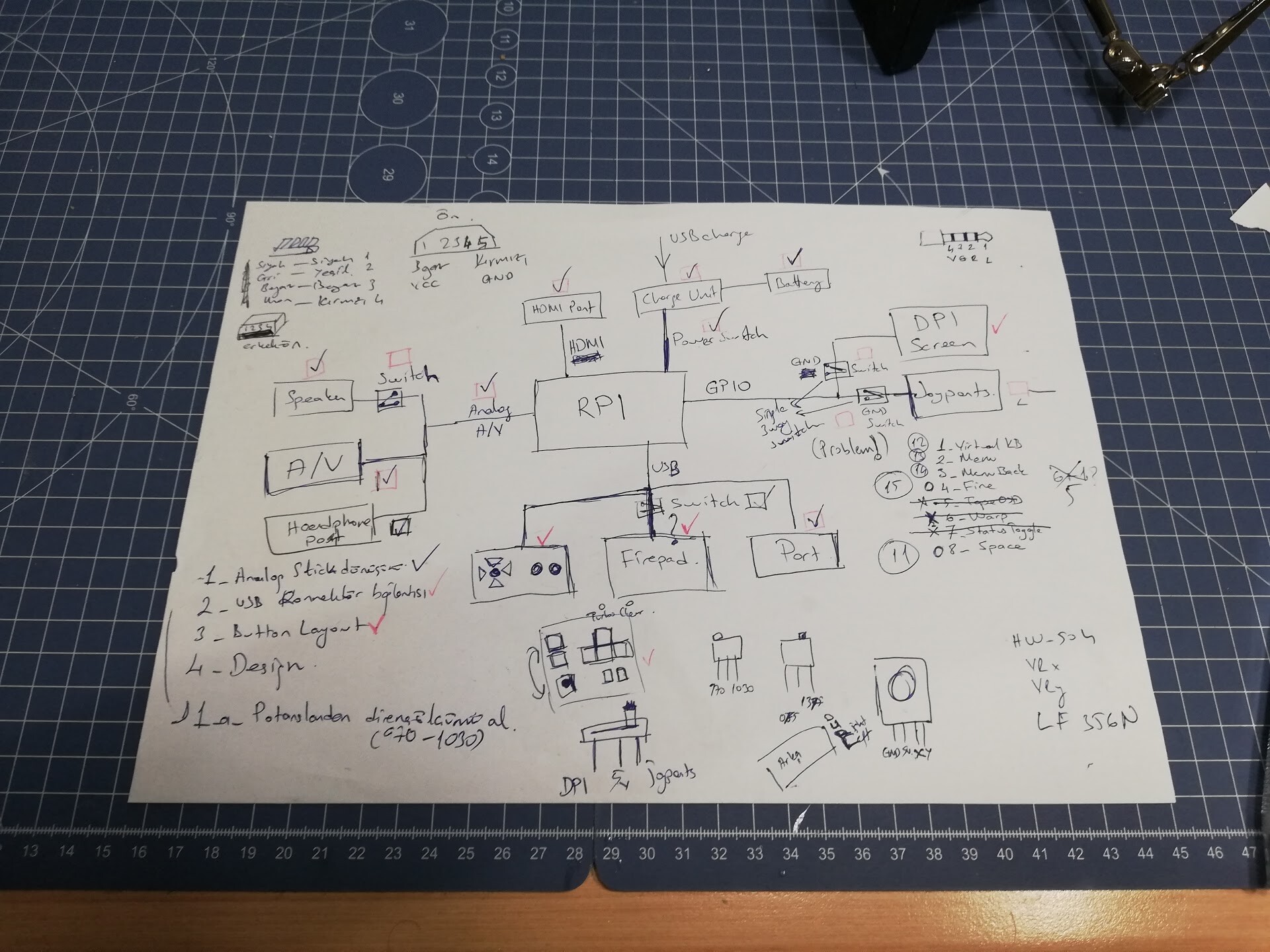
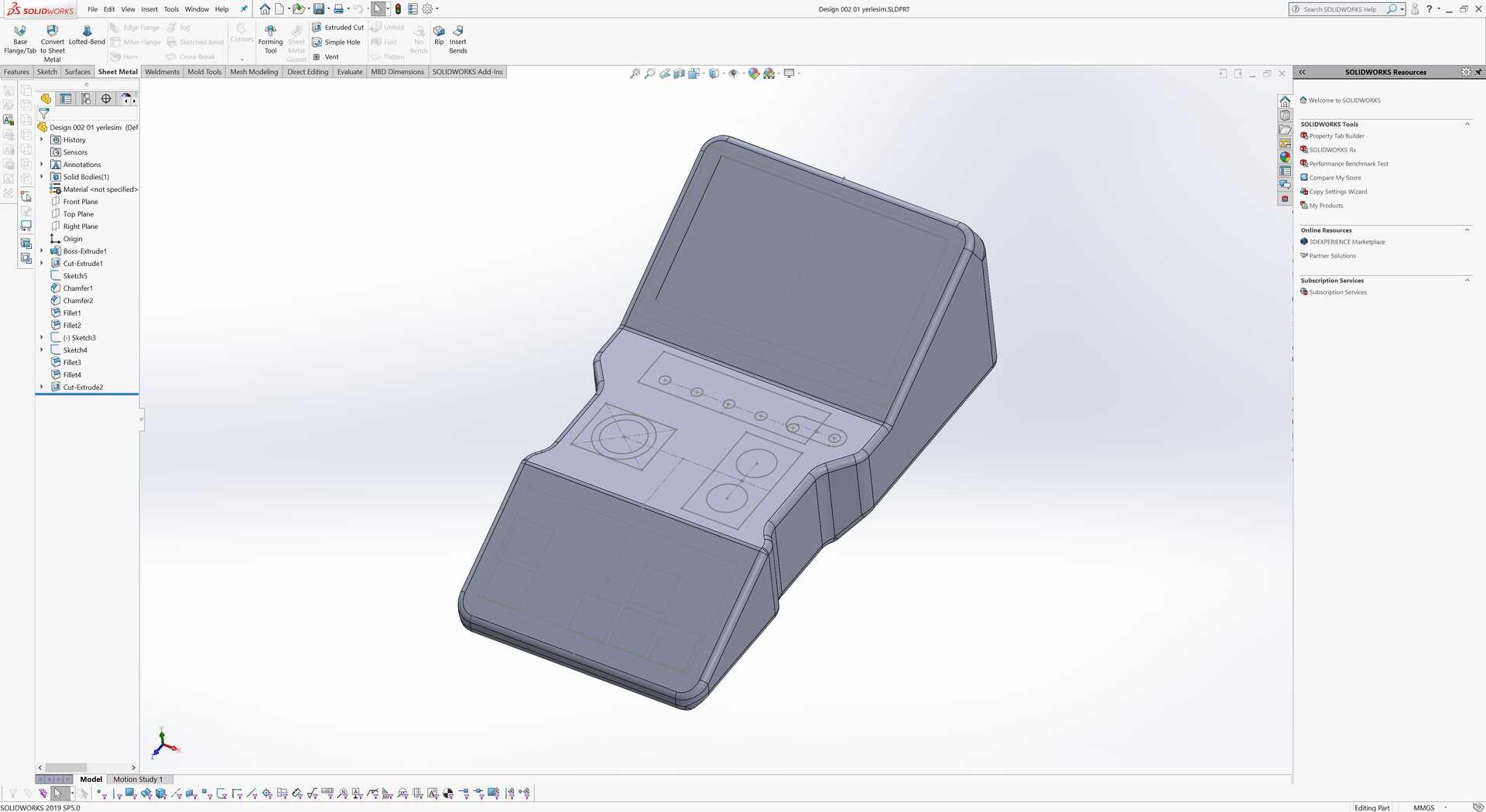
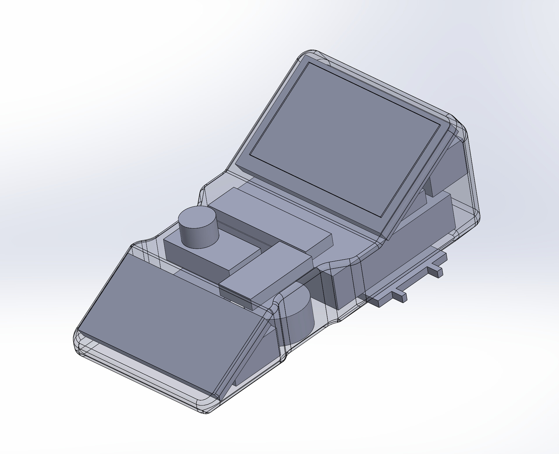
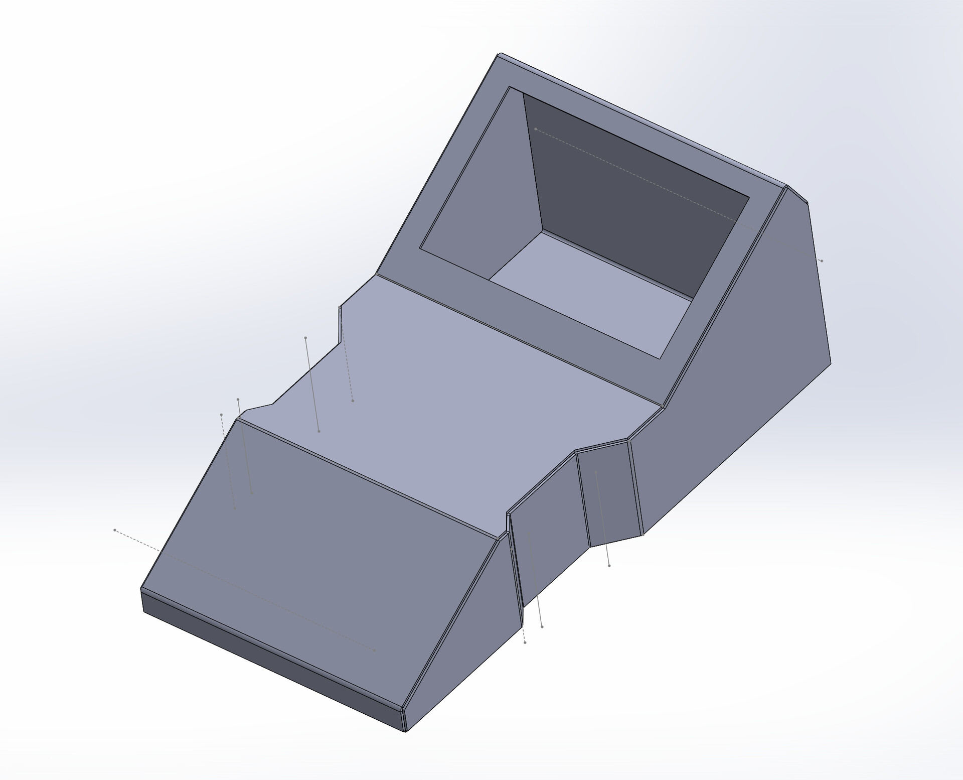
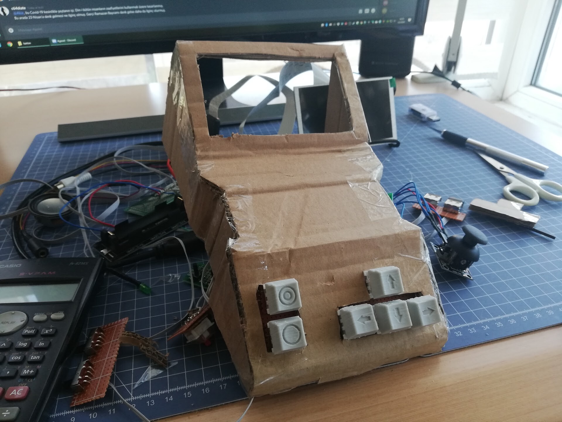
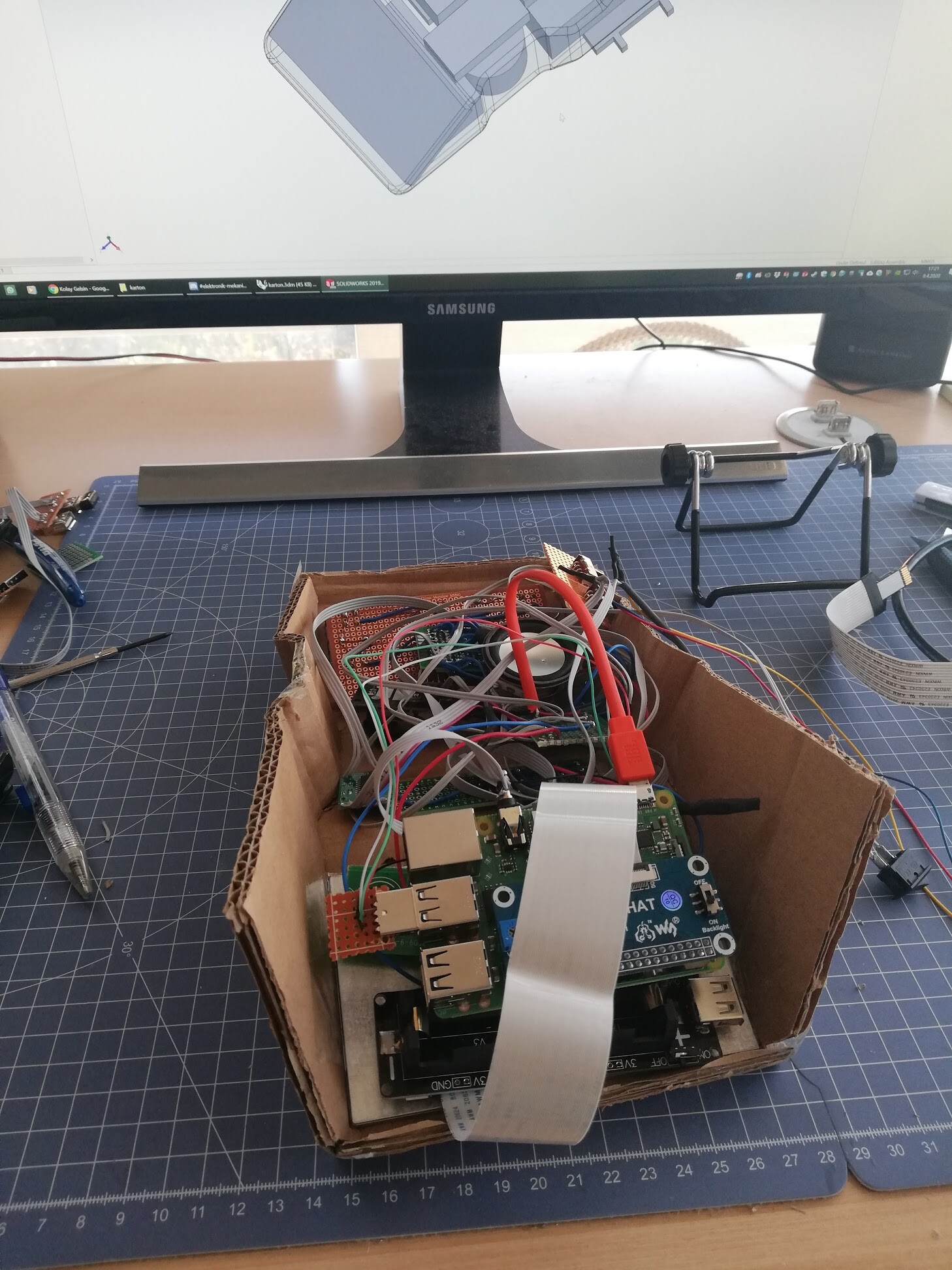
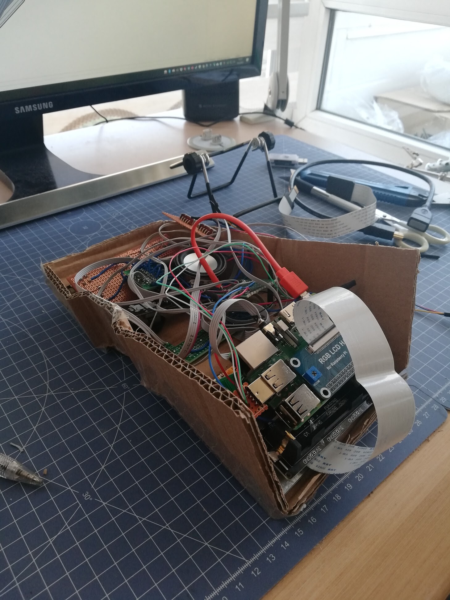
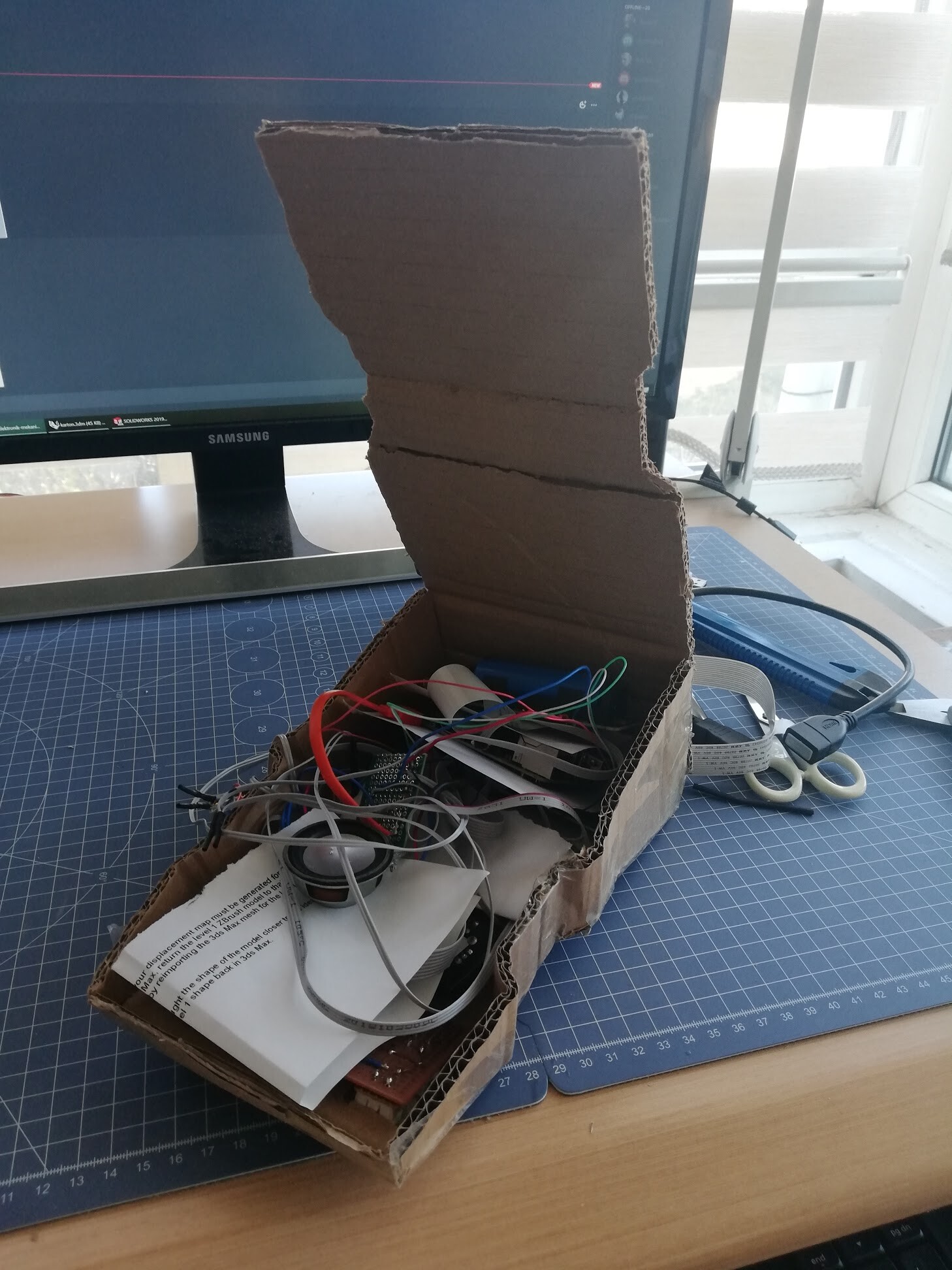
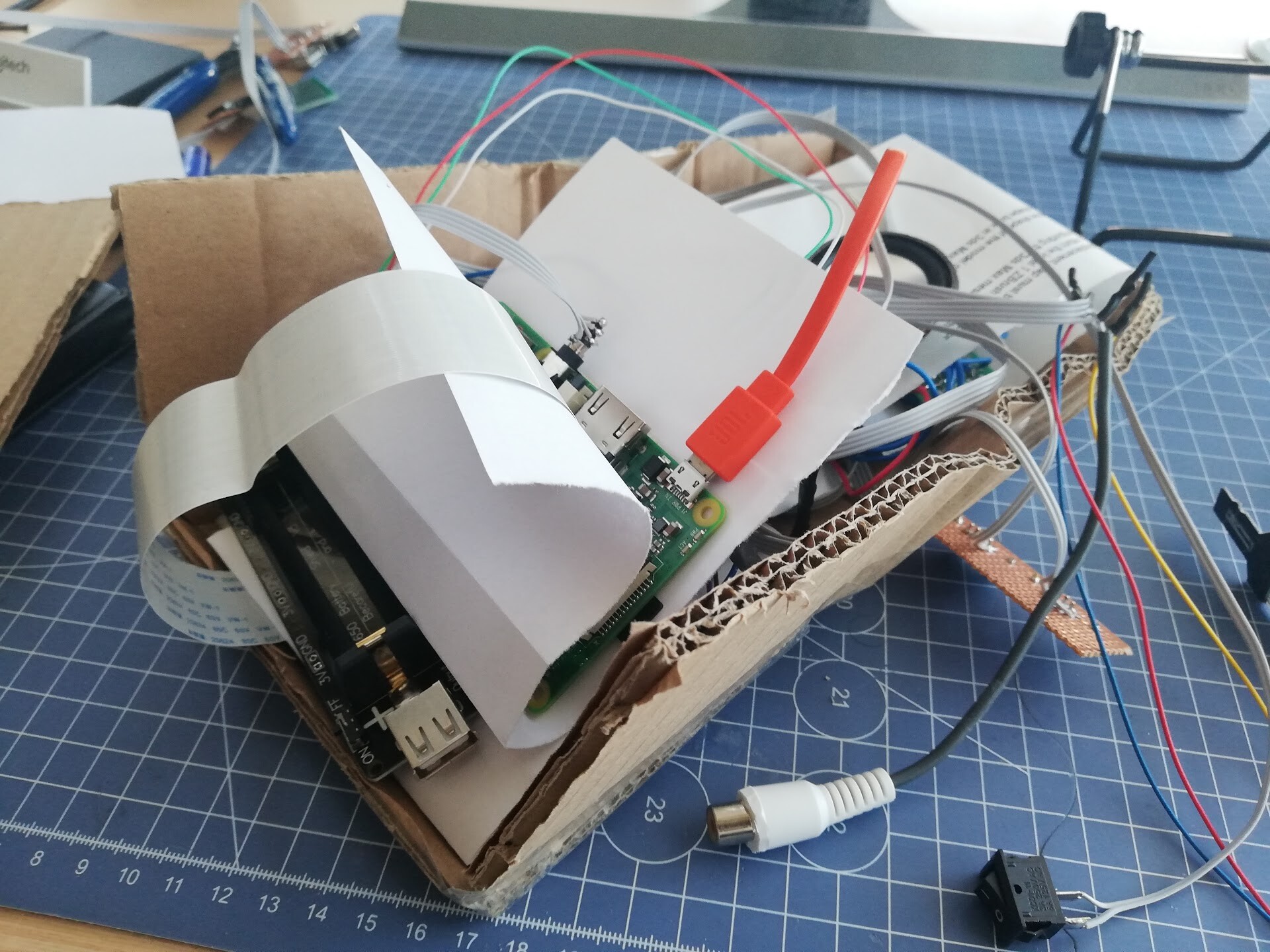
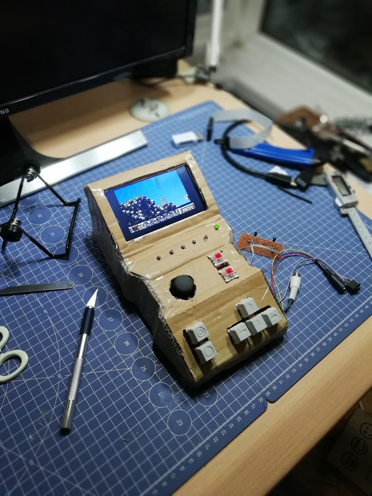
Next I started to create what I can do with limited pixels. My first approach to create the painting of one of my cool devices. Portable BMC 64 which is an hardware for emulating Commodore 64. 


You can see the details of my design by this link:

https://www.artstation.com/blockmind/blog/NgDK/portable-commodore-64-design-with-bmc-64-emulator 


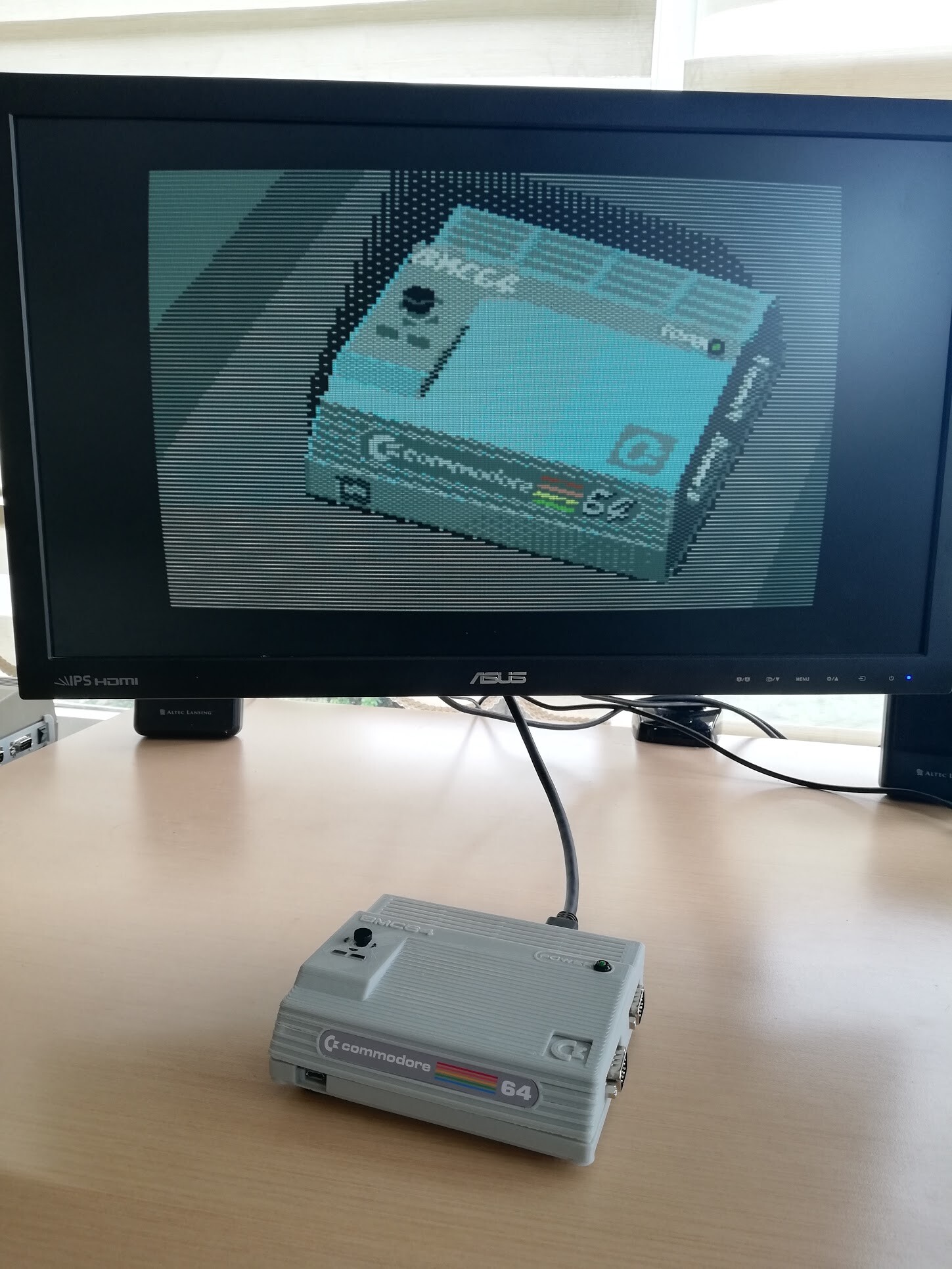
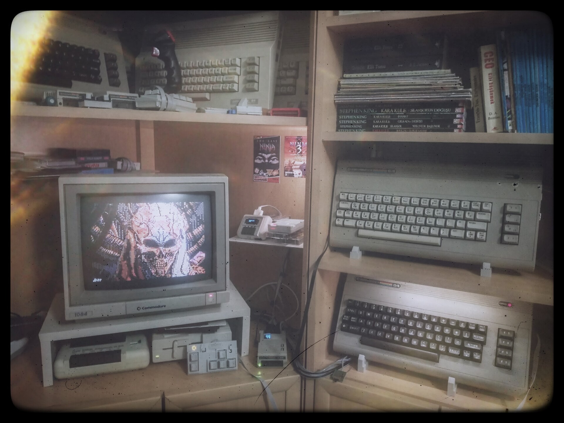
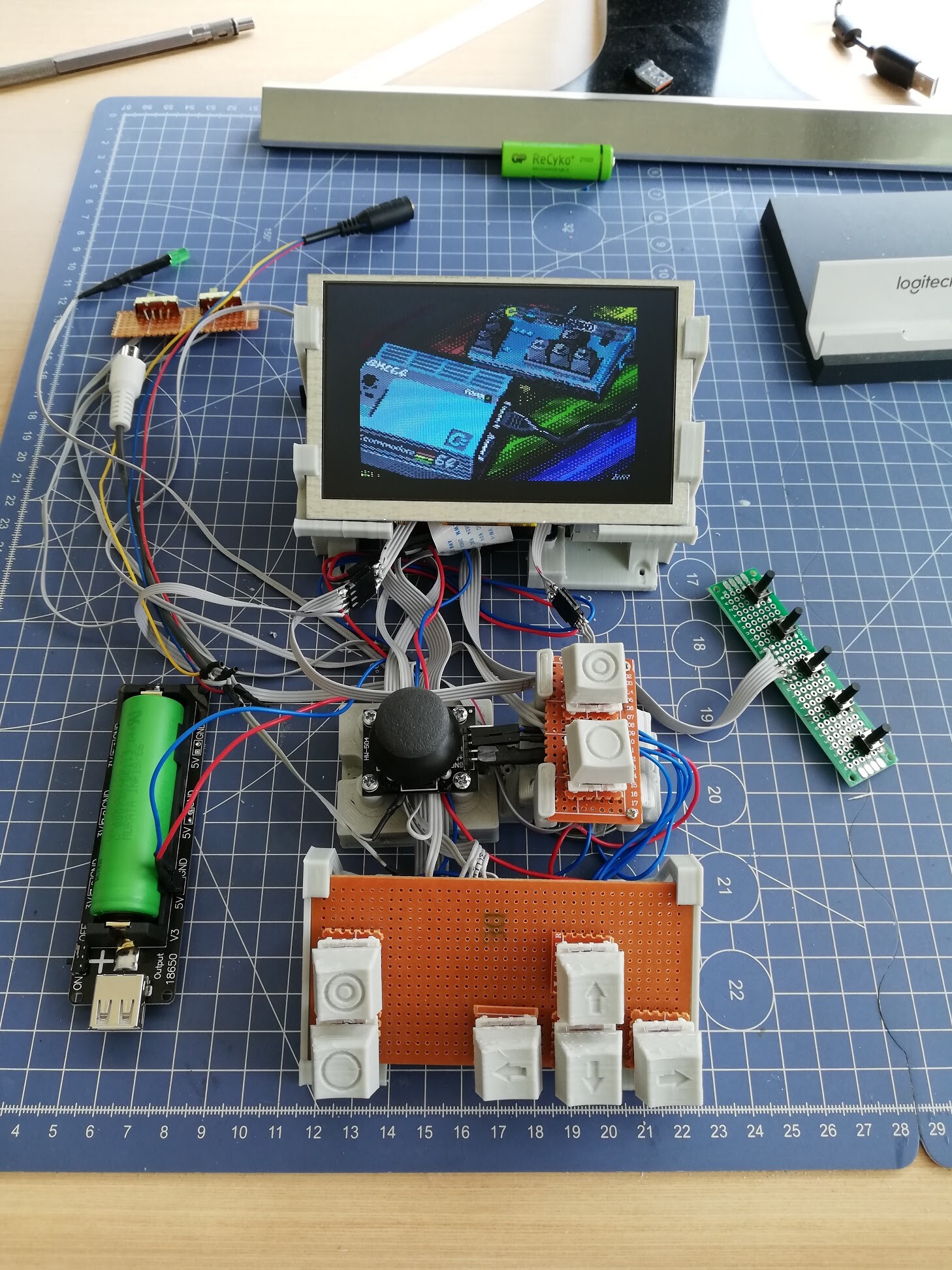
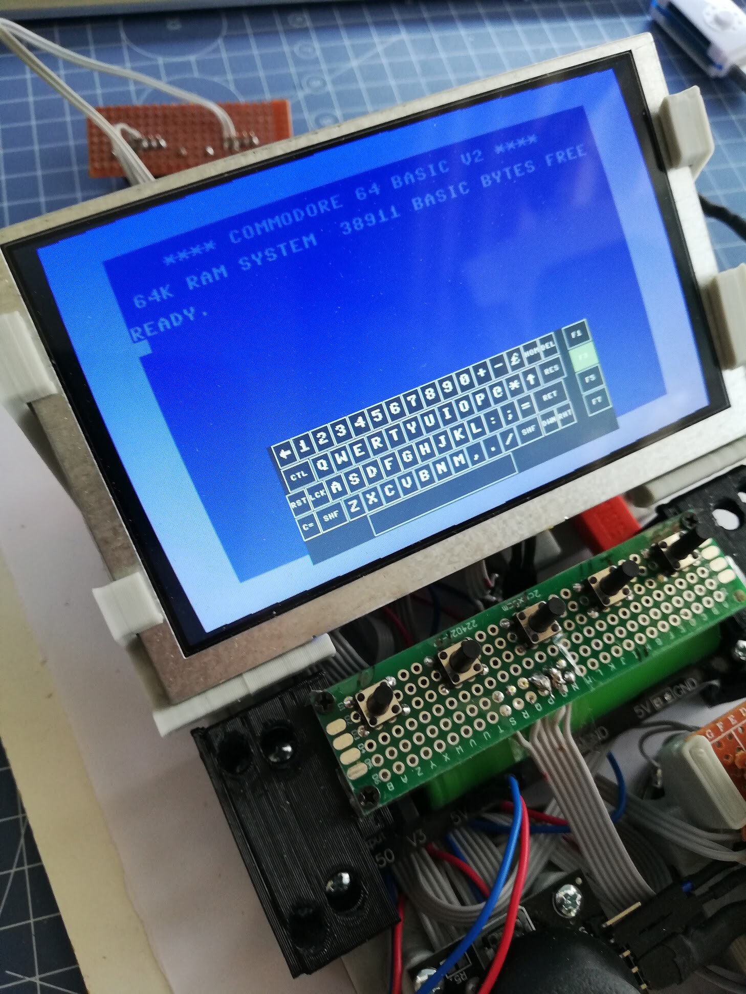
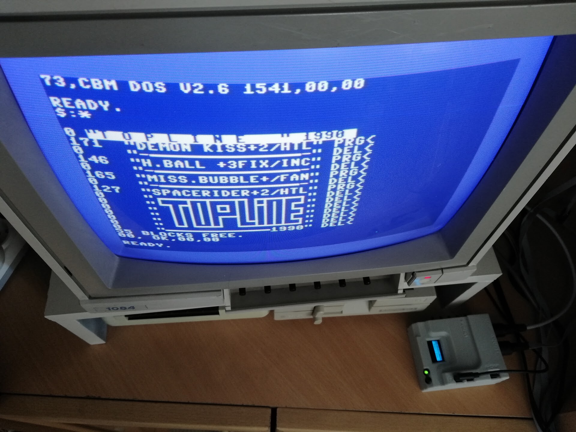
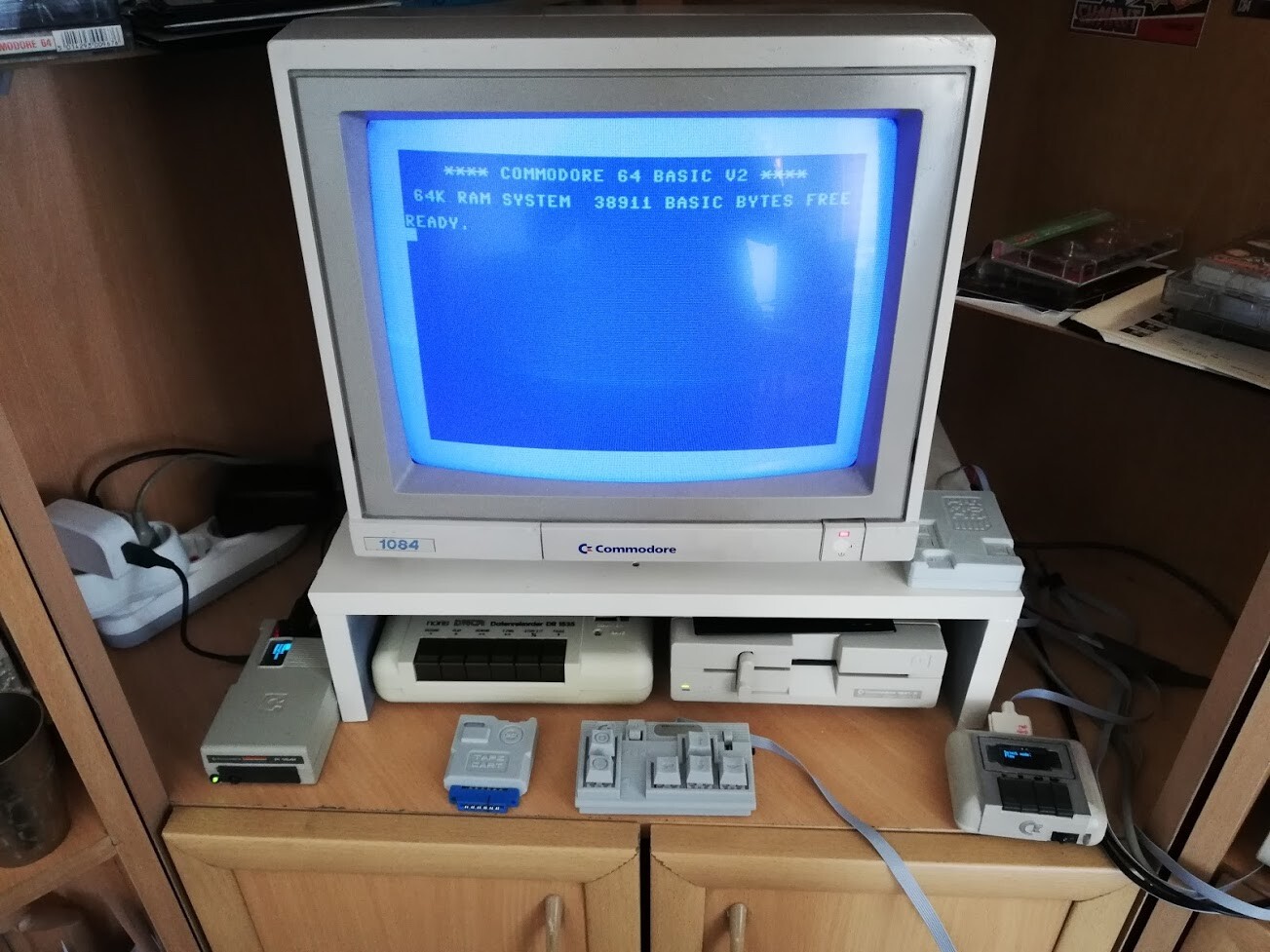
I loaded the very C64 bitmap with using the emulator itself on the picture. Nice kind of "inception", eh?

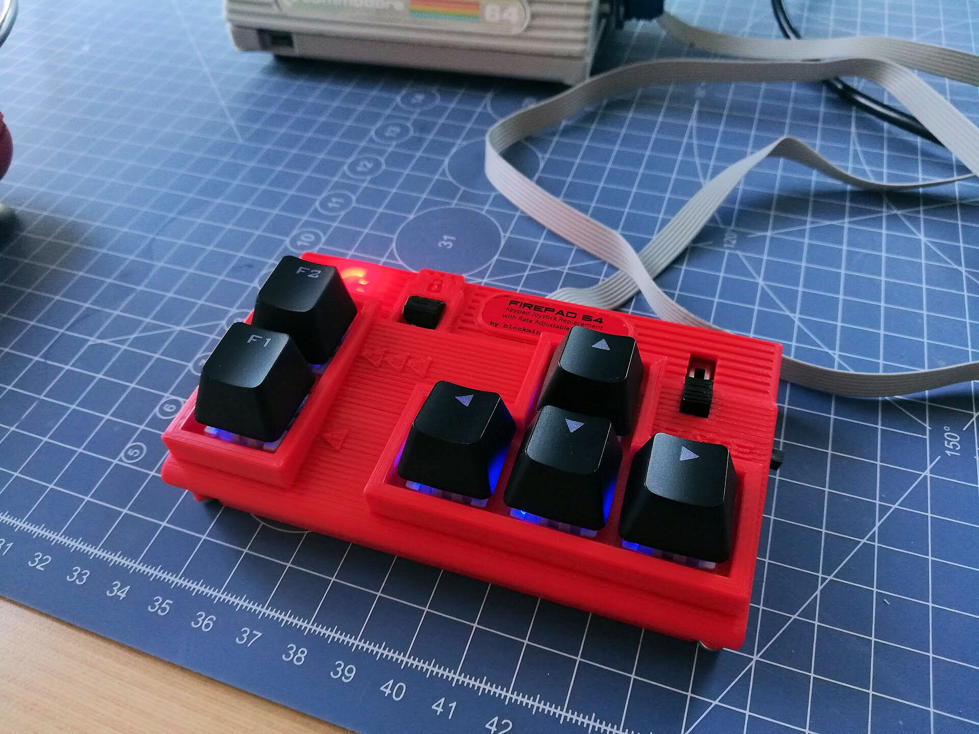
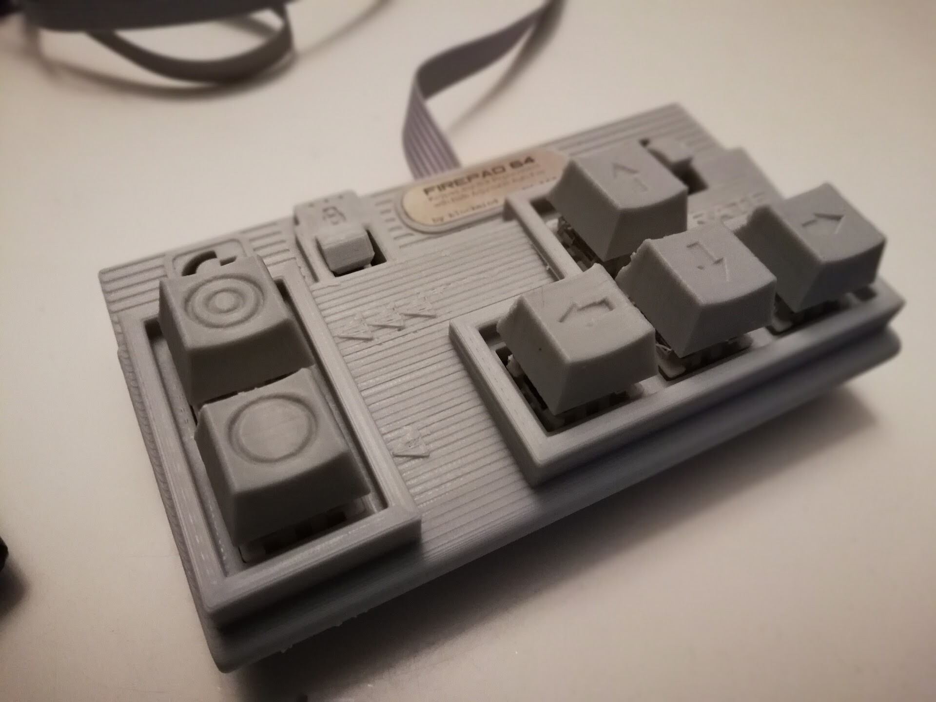
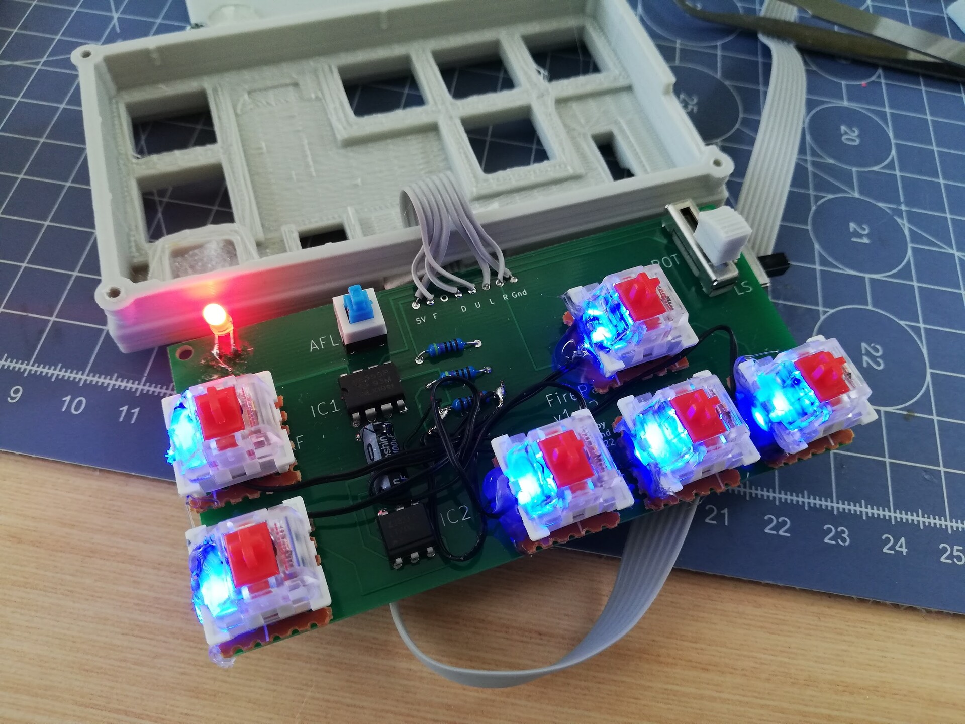
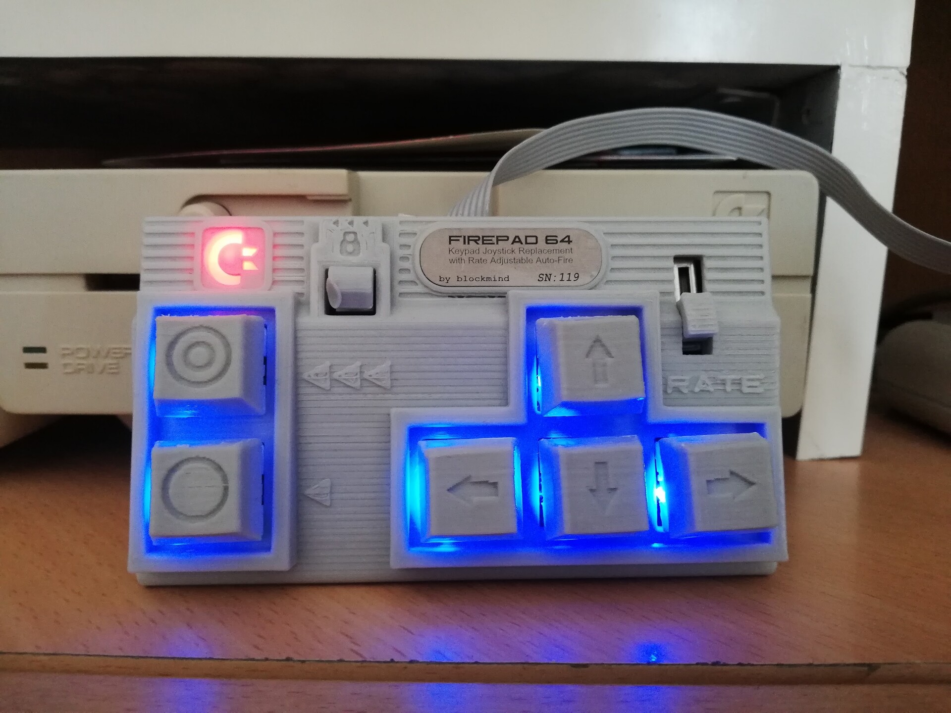
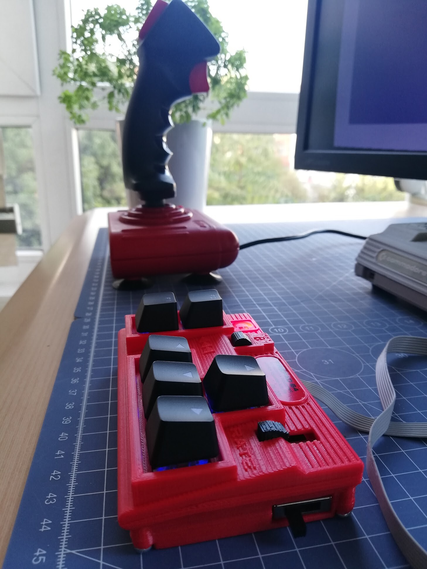
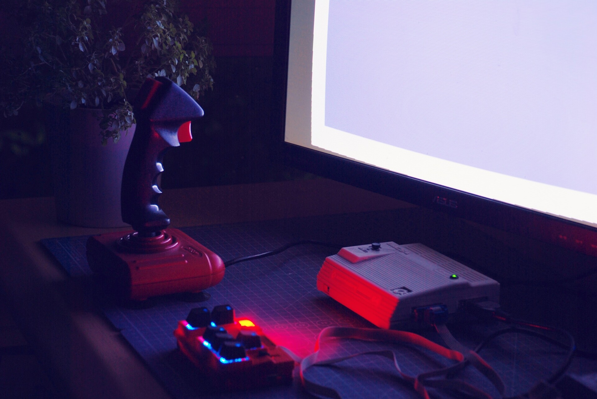
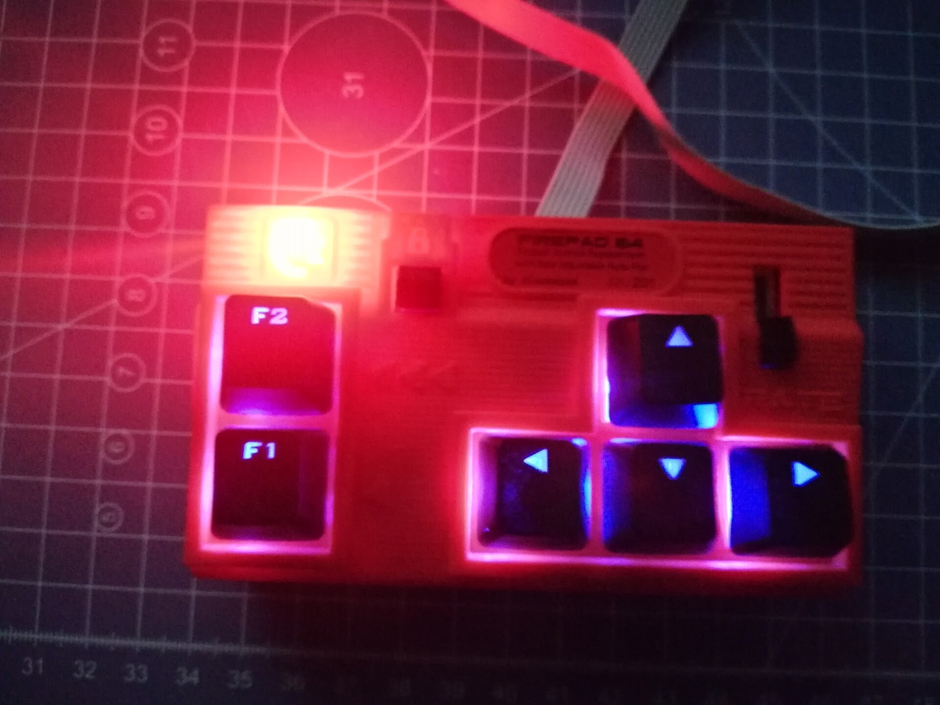
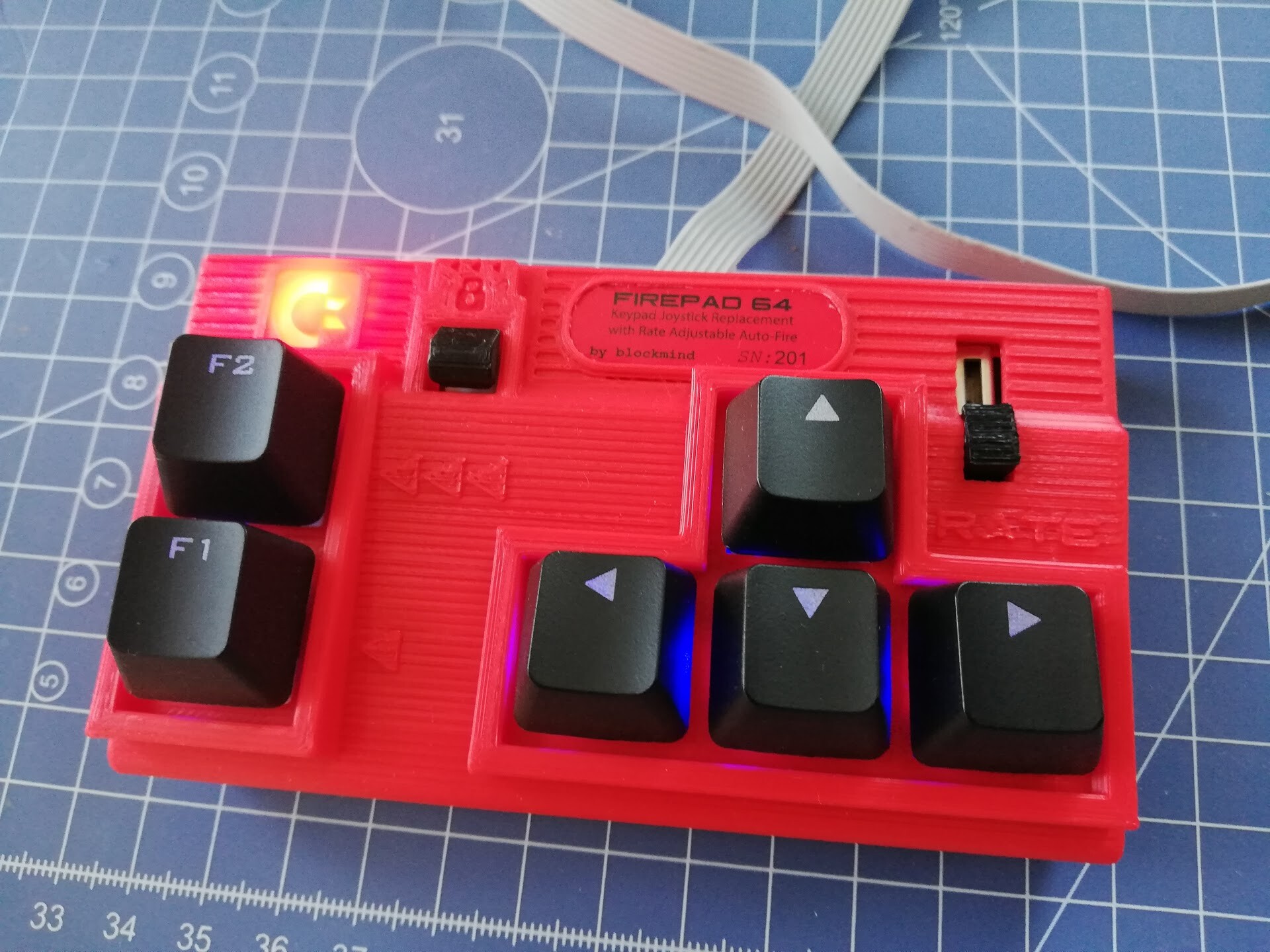
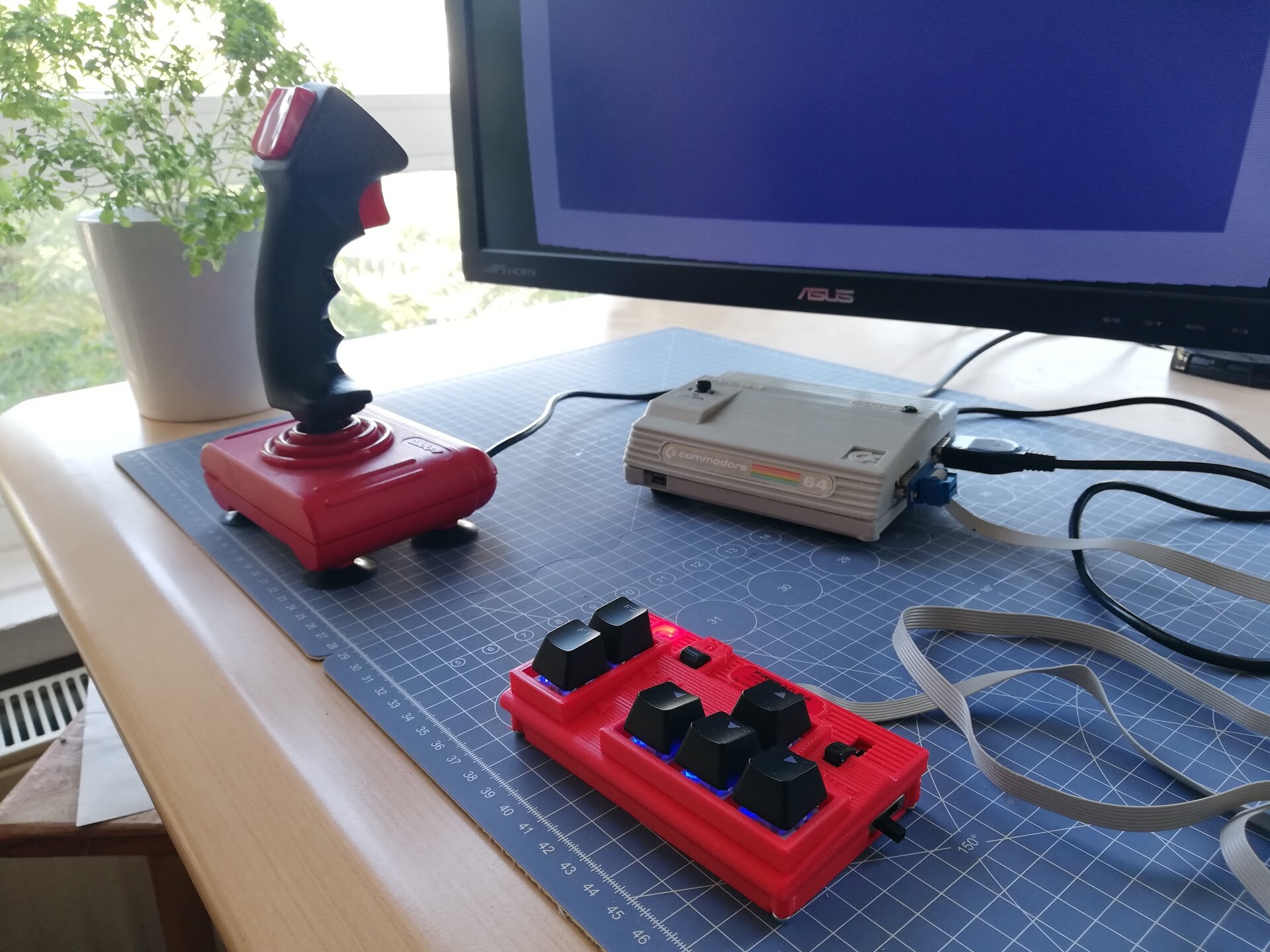
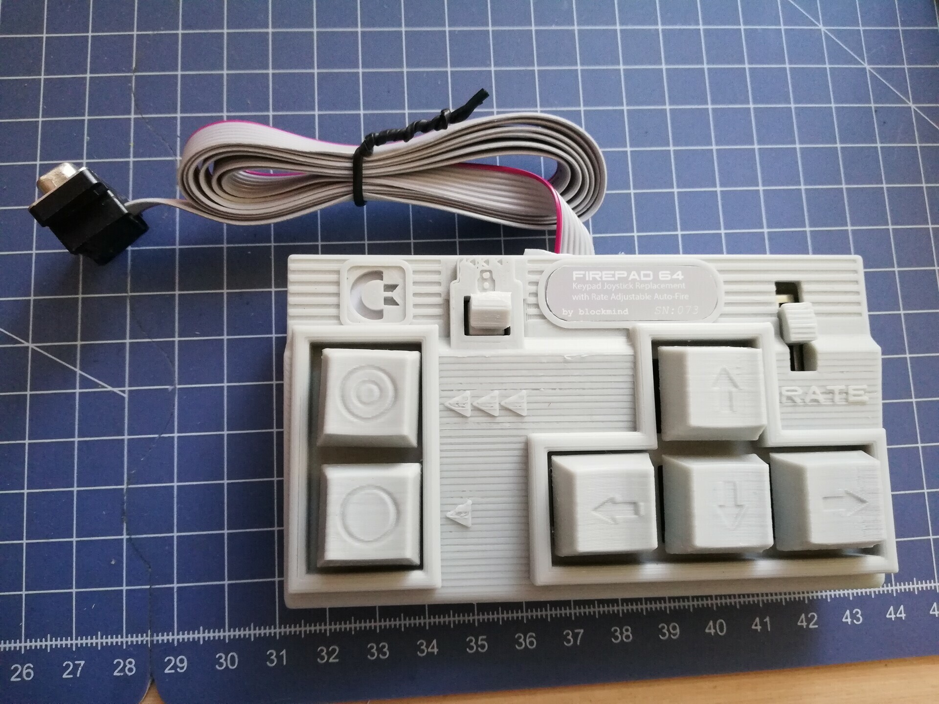
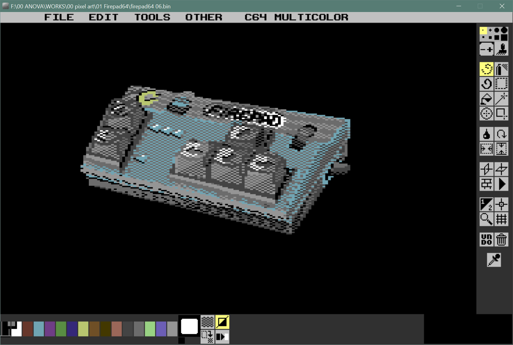
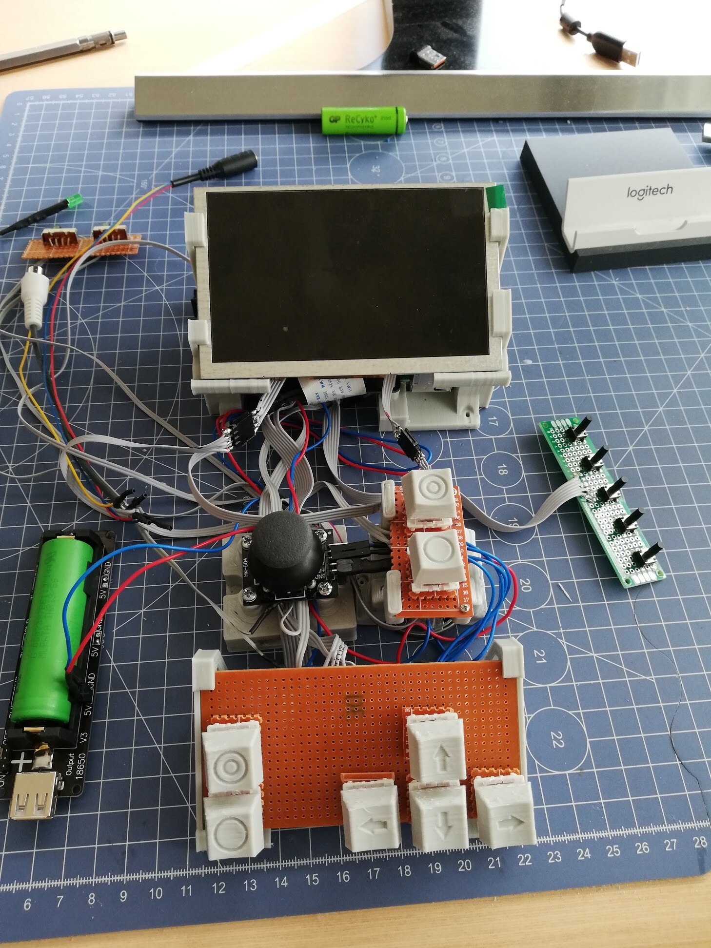
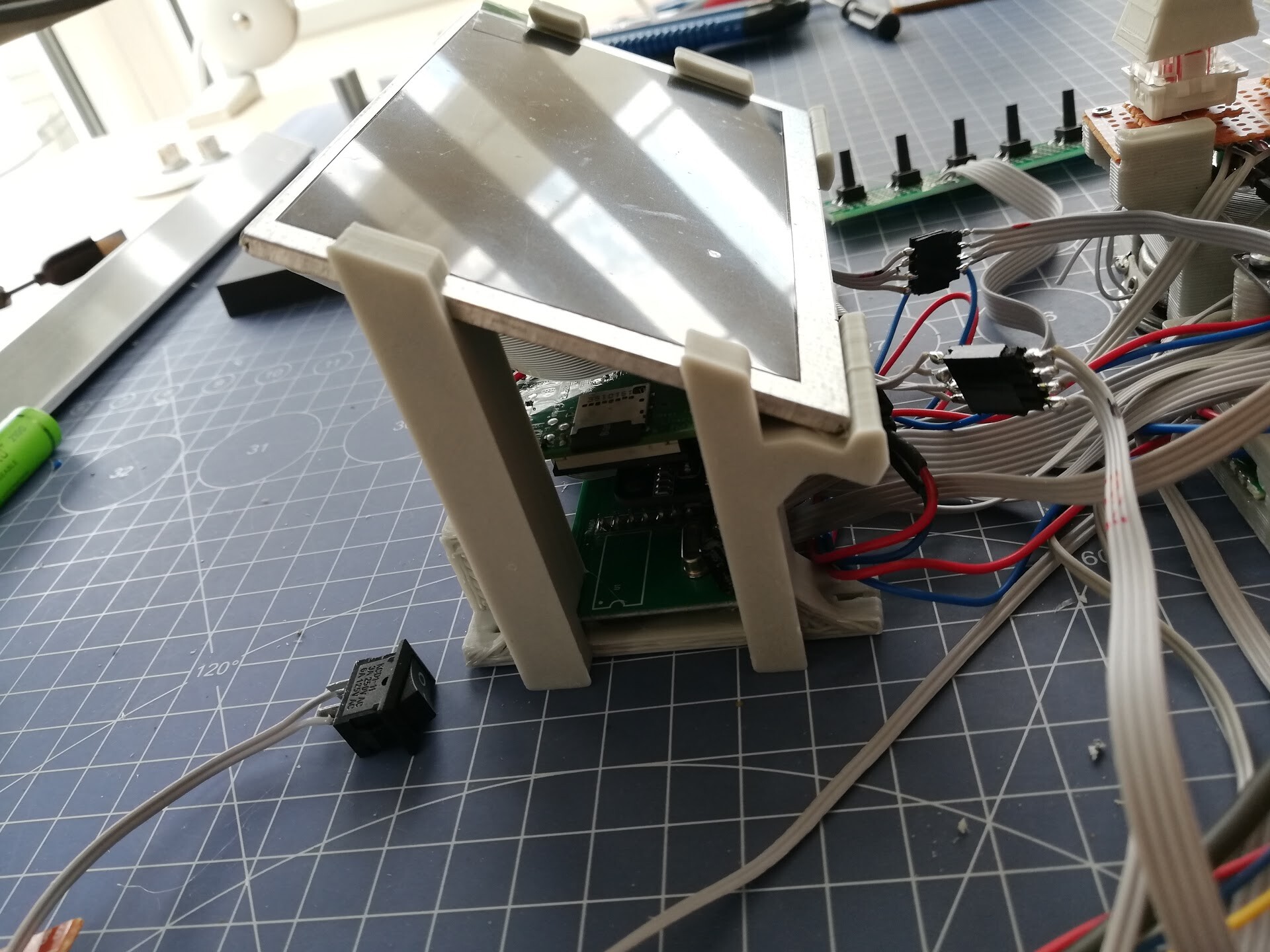
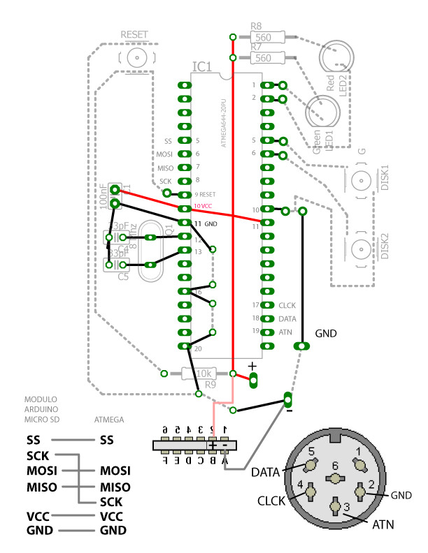
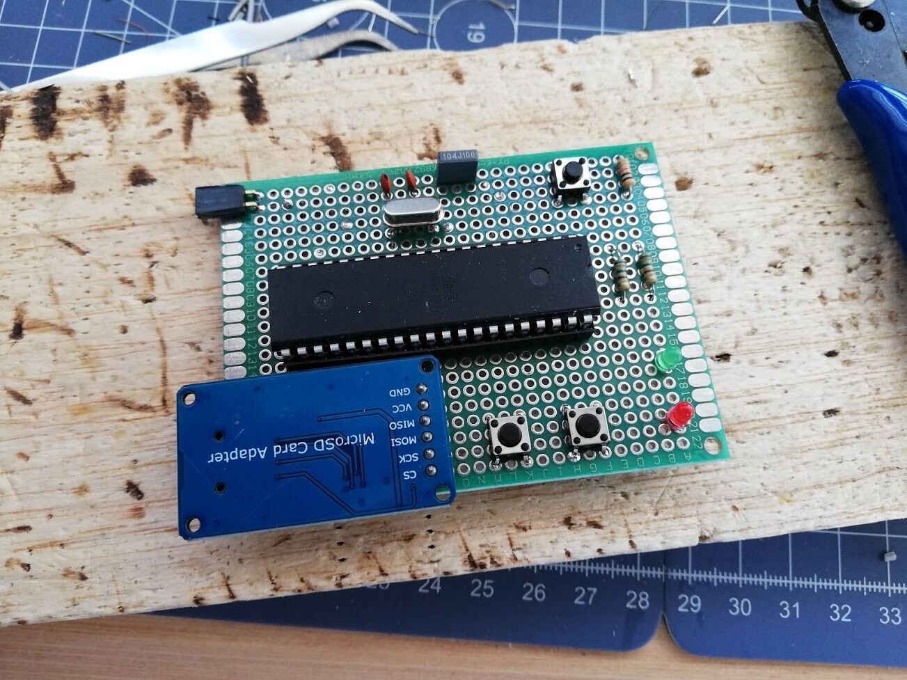
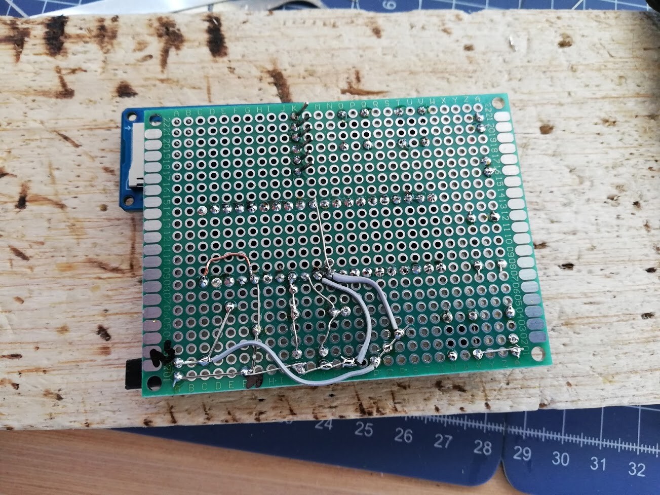
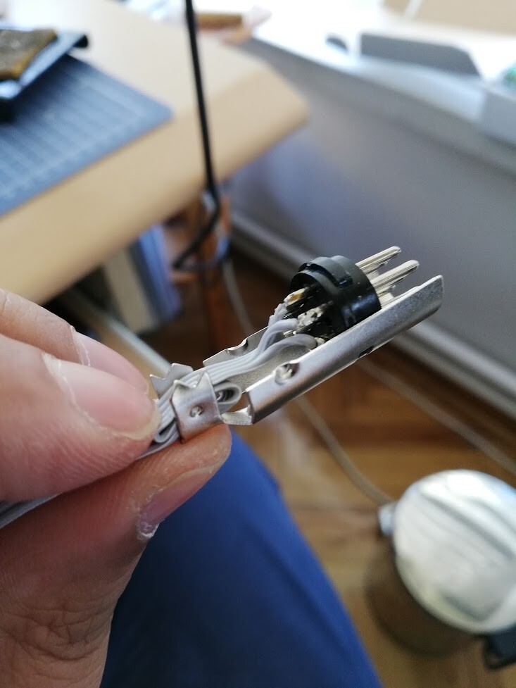
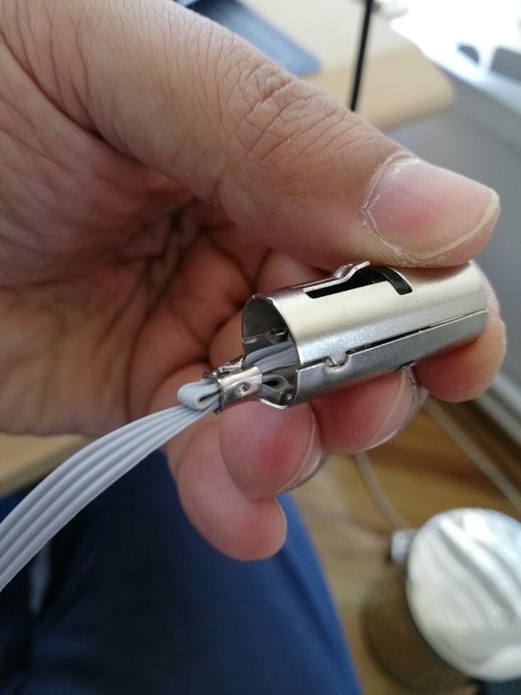
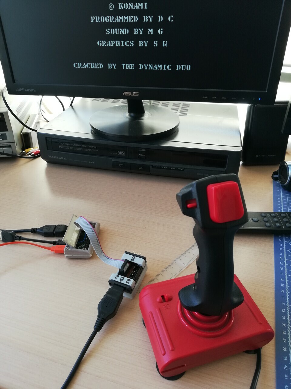
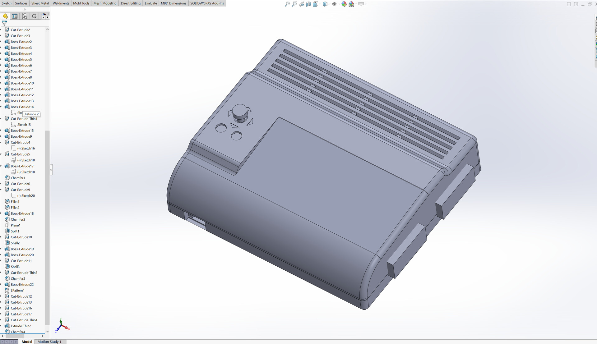
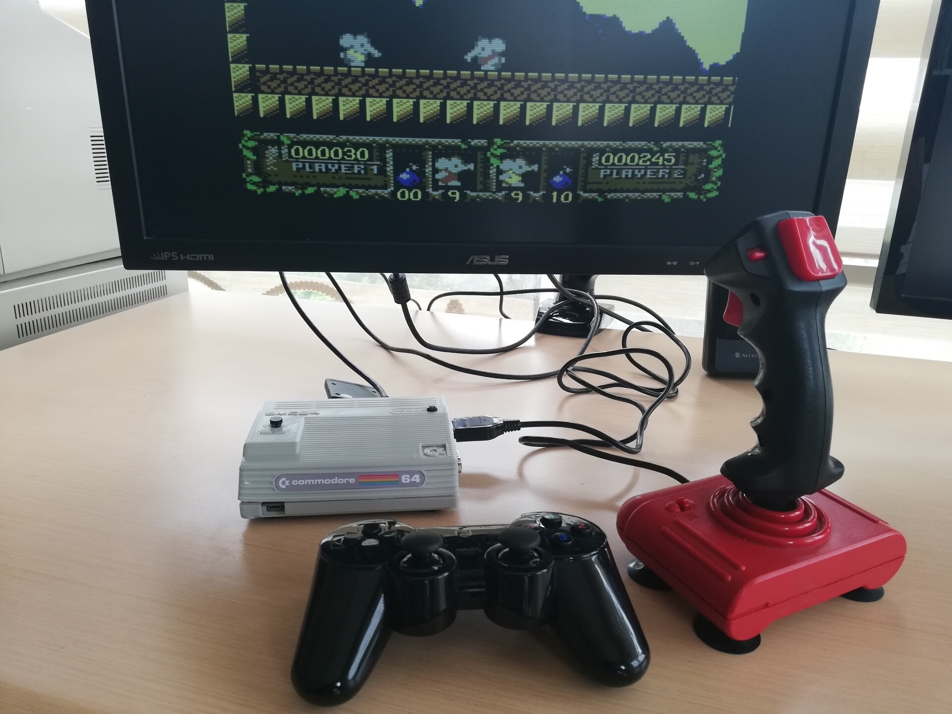
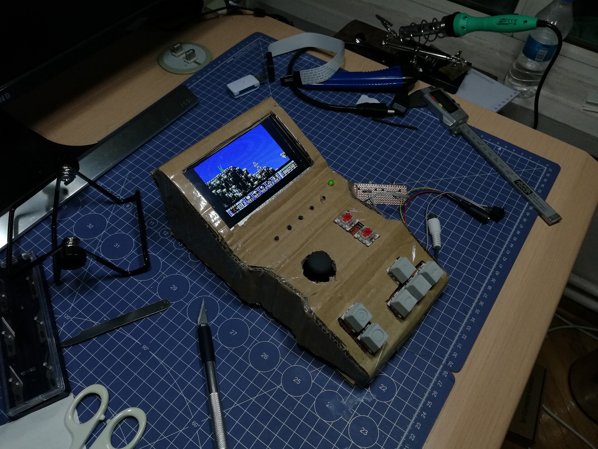
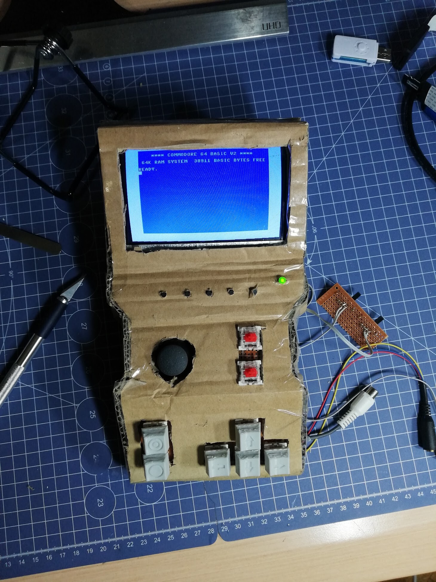
Next I go for the Firepad 64 device which I designed before. You can see what Firepad64 is by this link:

https://www.artstation.com/blockmind/blog/zPLm/making-of-firepad64-joystick-replacement-for-commodore-64 

and this (Turkish): https://www.artstation.com/blockmind/blog/zPLm/making-of-firepad64-joystick-replacement-for-commodore-64 


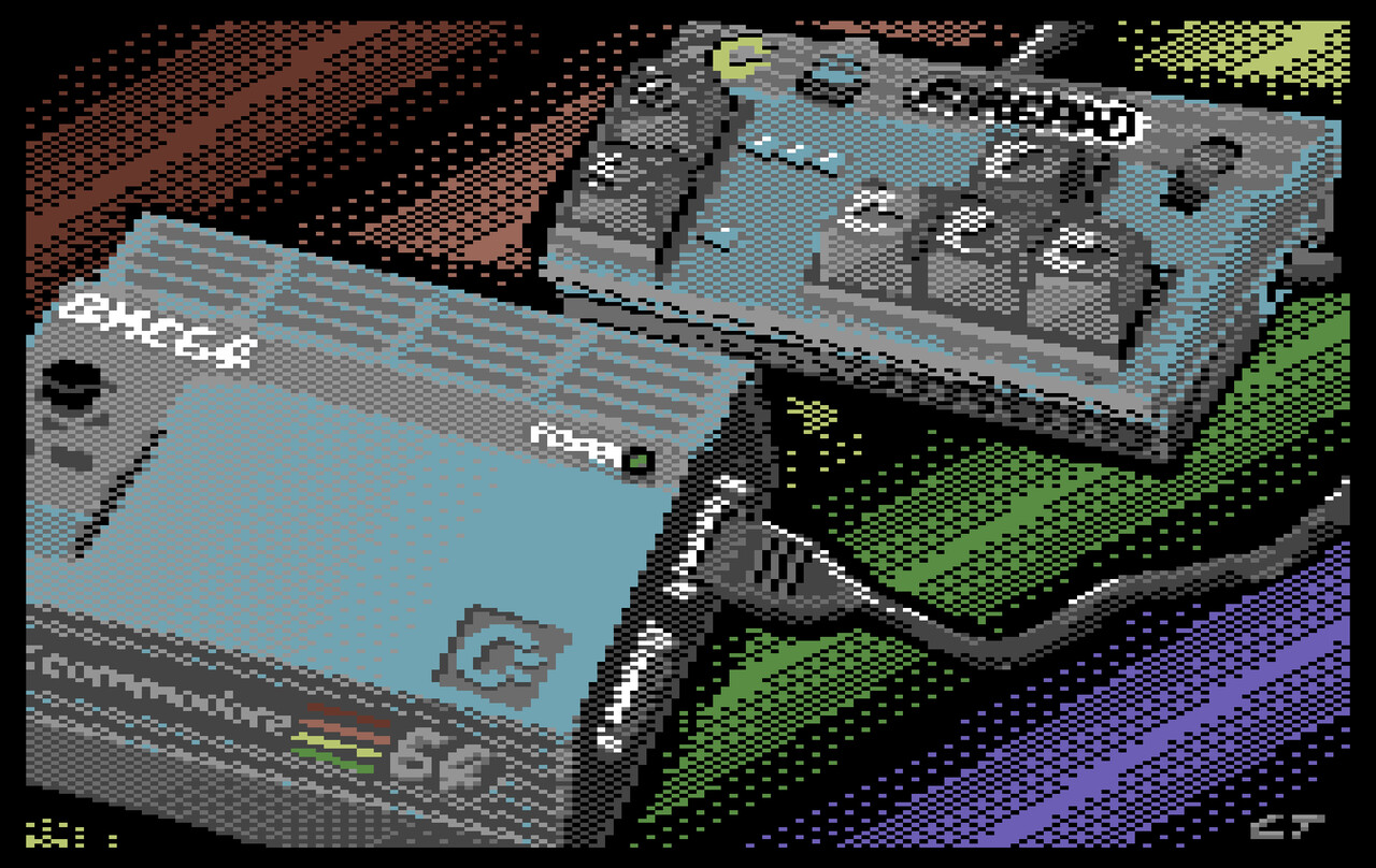
This time I recorded the whole process, and created a timelapse video. As you can see on the video. I combined the Firepad64 illustration with the BMC64 image. 

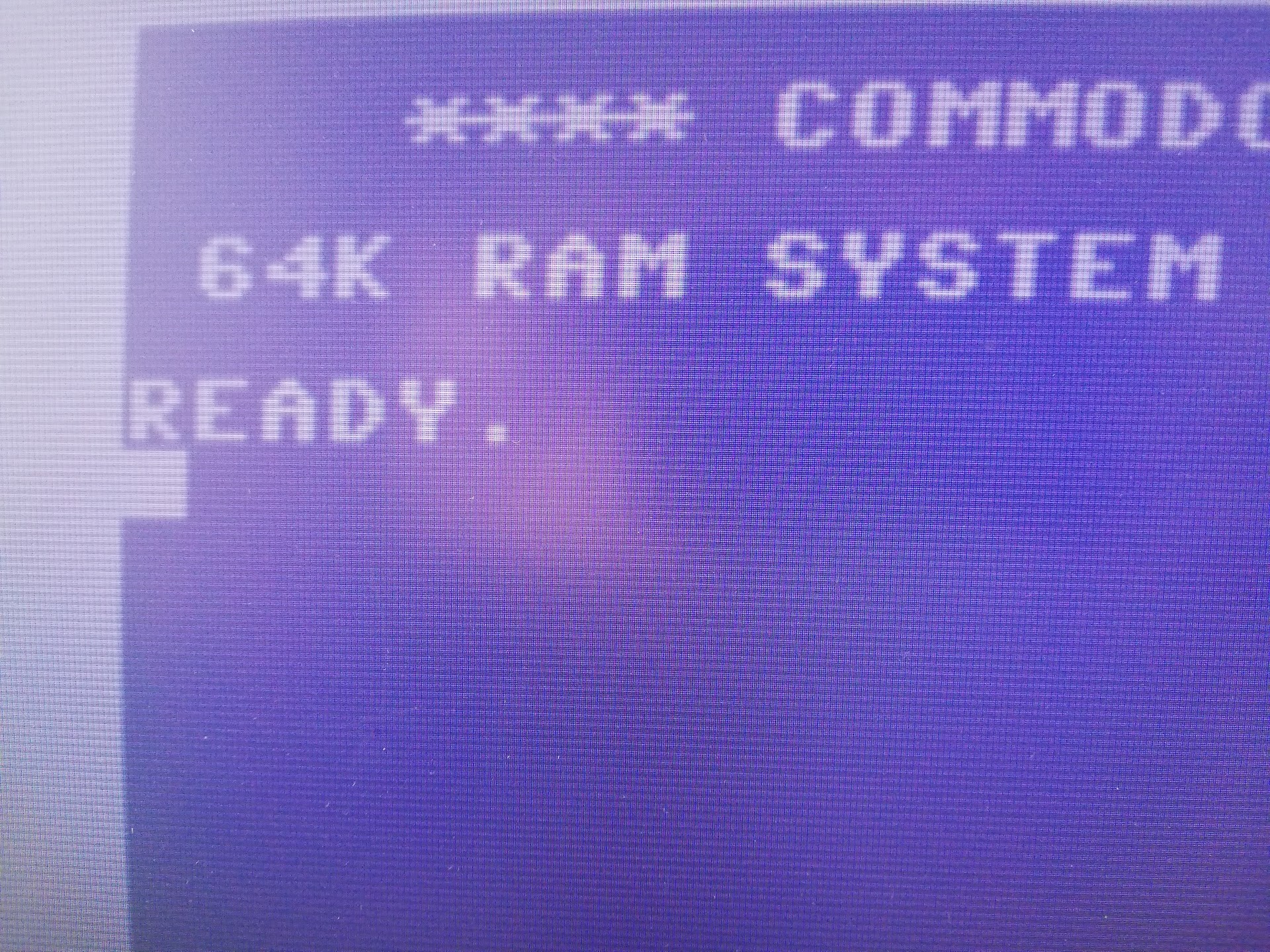
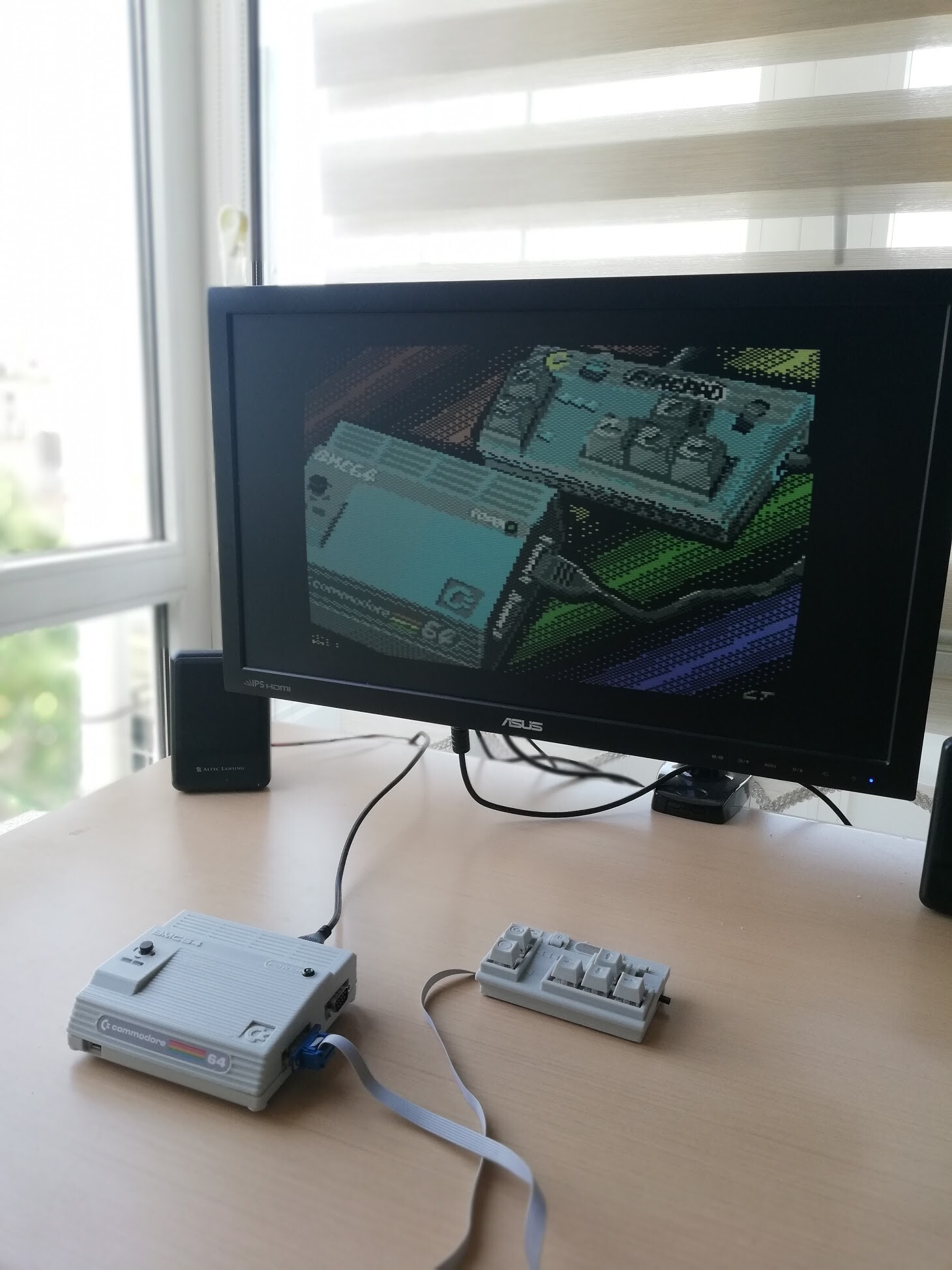
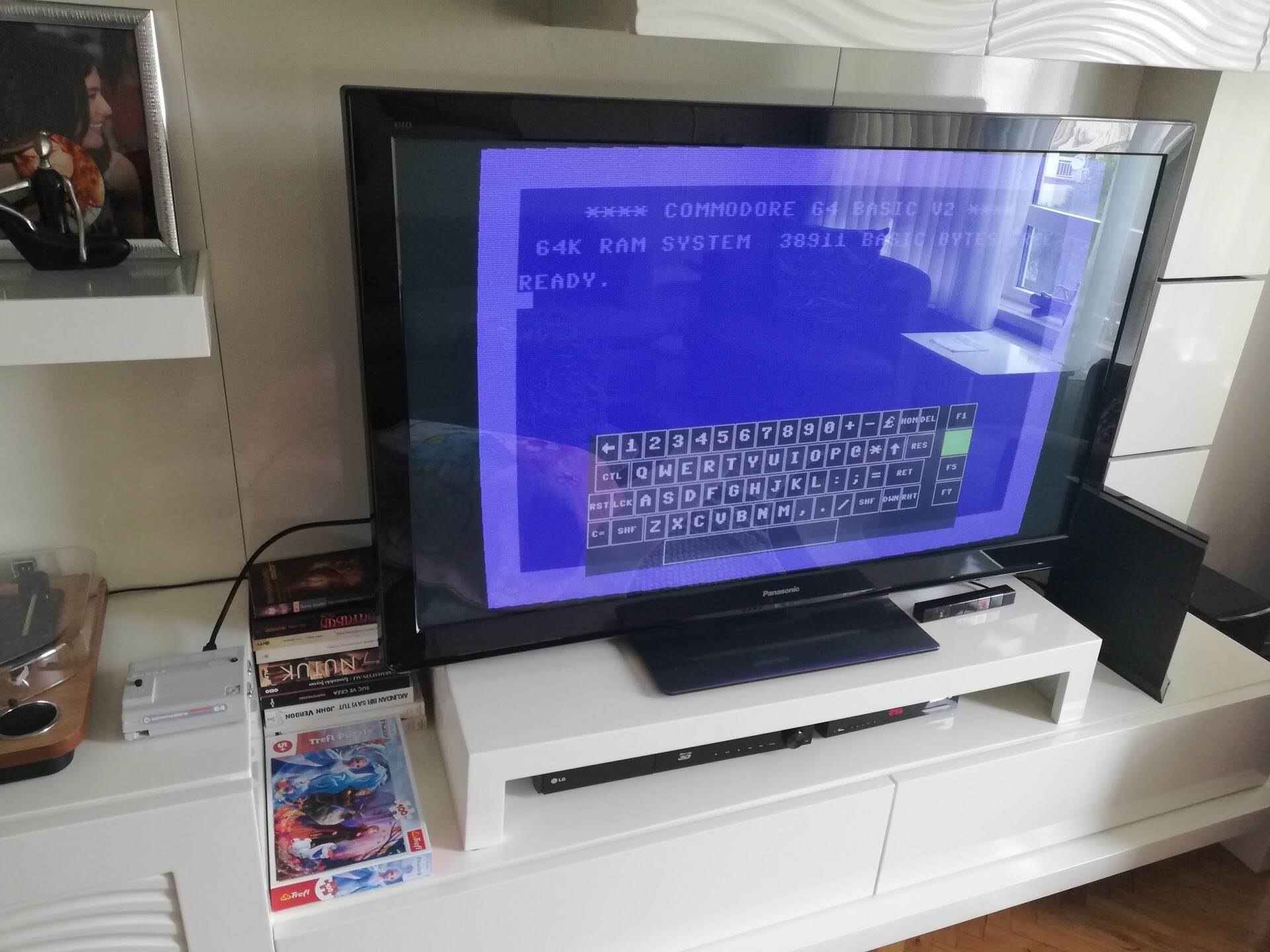
Let's load the image in a Commodore 64 emulator by itself :)

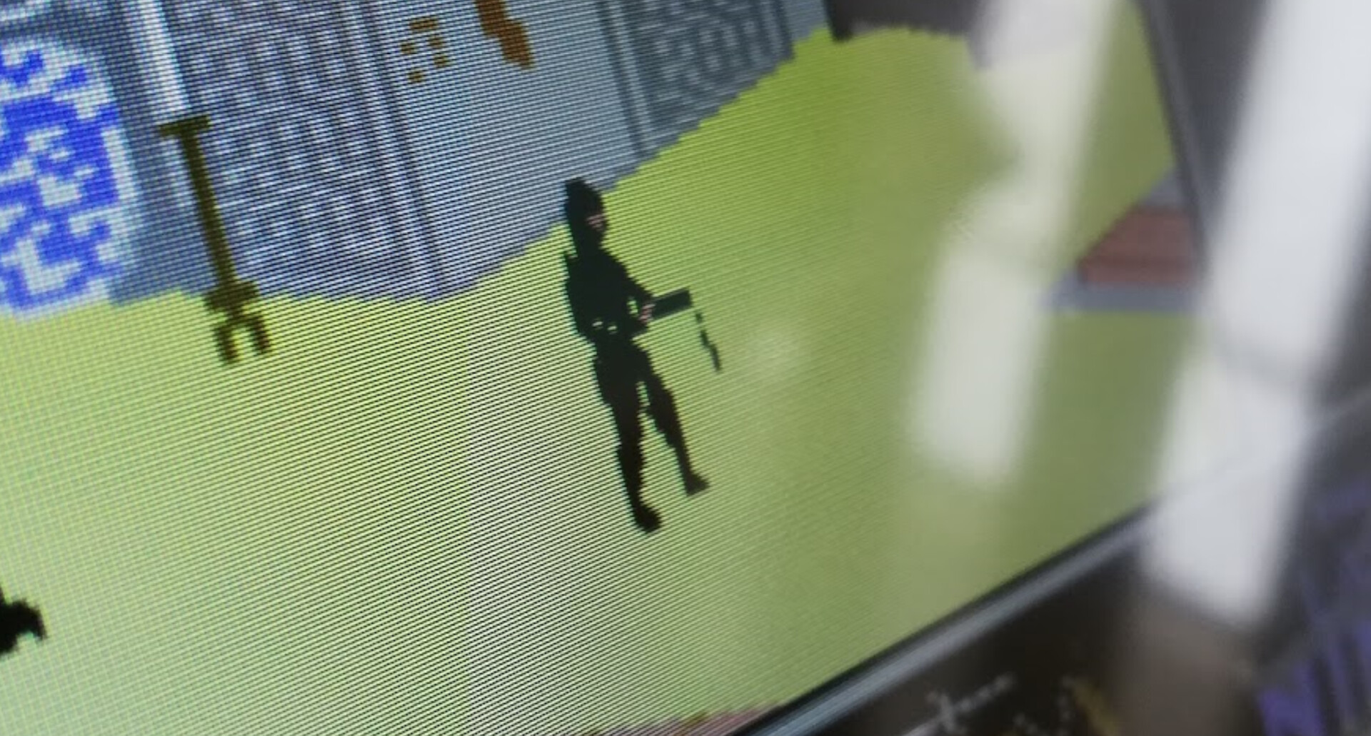
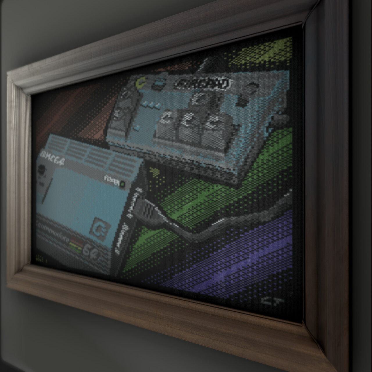
Since resolution is low, color transitions are too sharp because of the pallette color count, well, scanlines and CRT effect is a necessity when it's come to pixel art. 

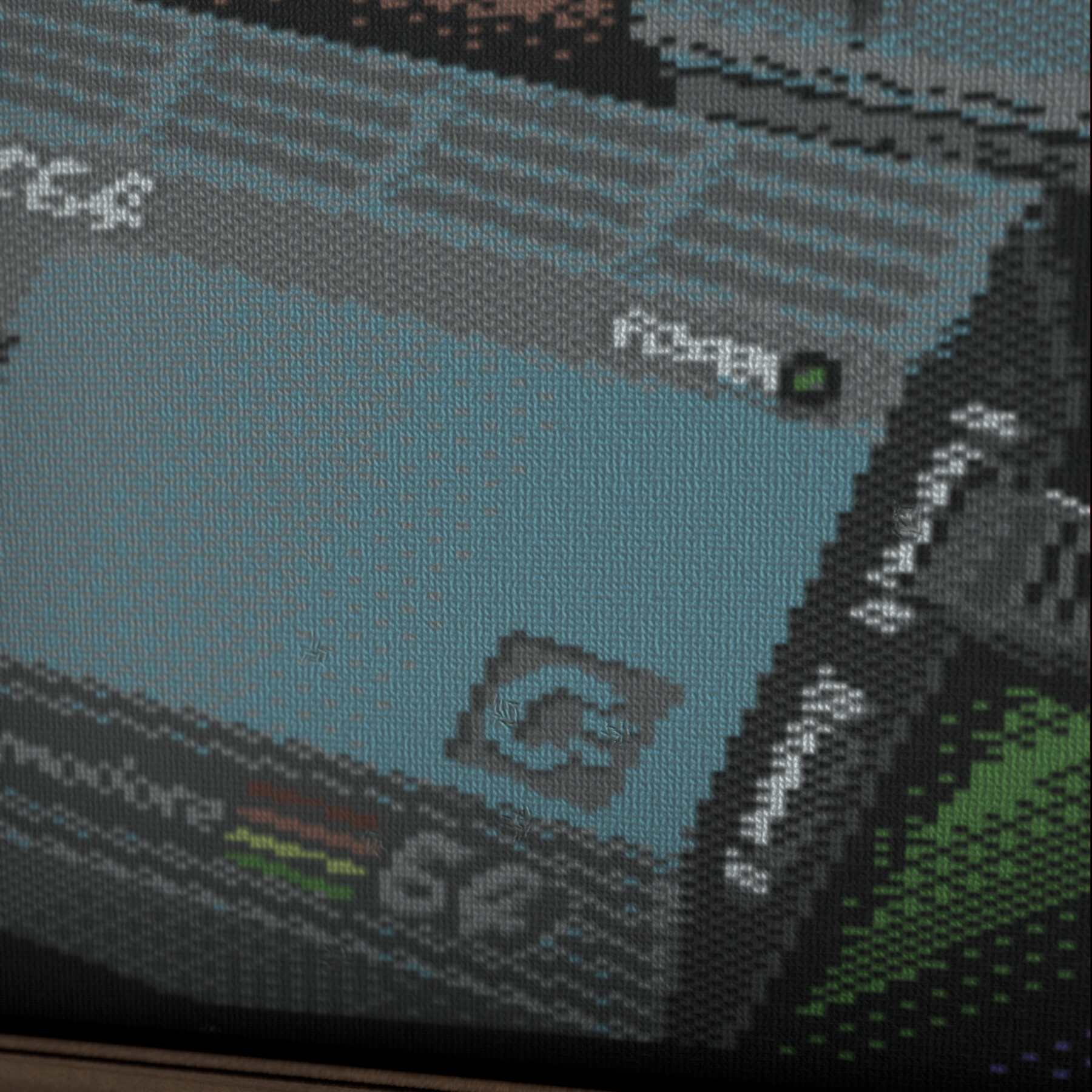
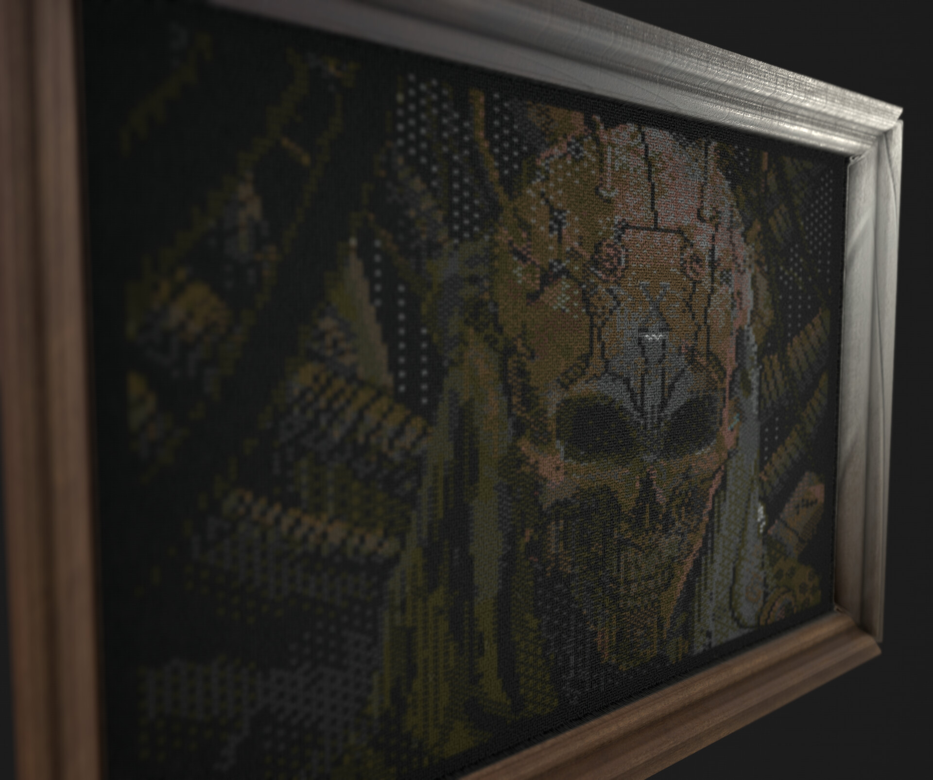
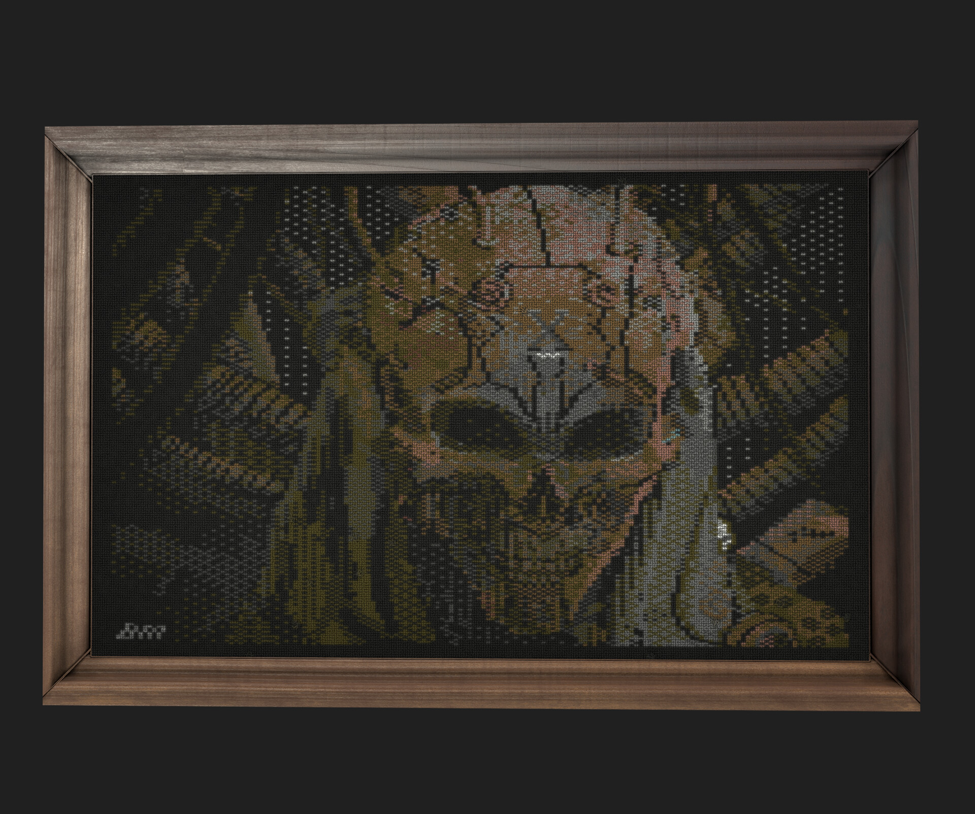
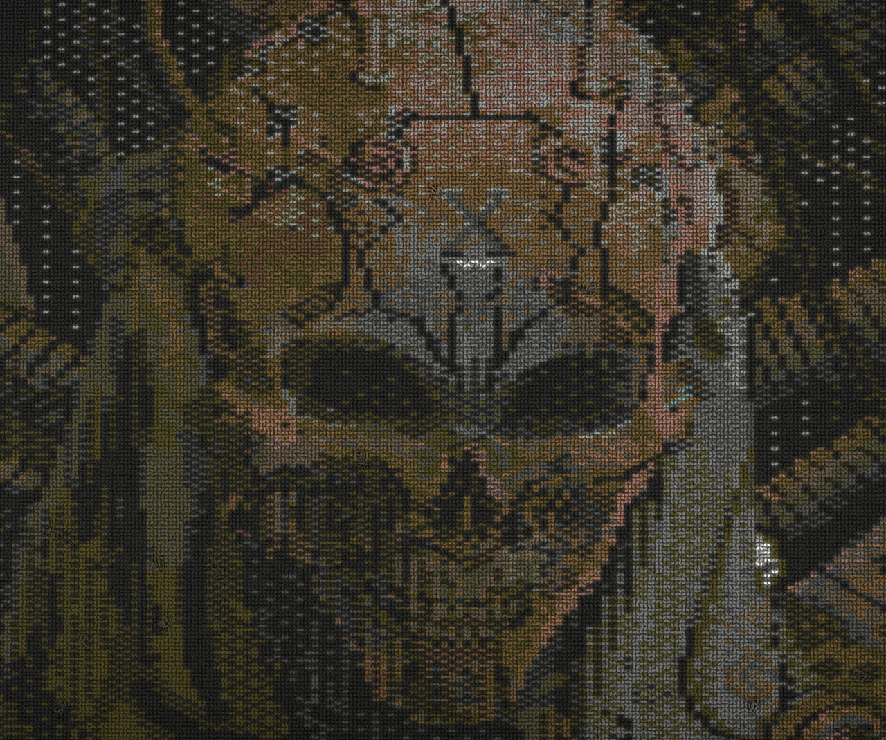
Or can embroidery replace the CRT effects one day? :)


(BTW you can grab your free copy of Pixel art embroidery by this link: https://www.artstation.com/artwork/0XgWnV)

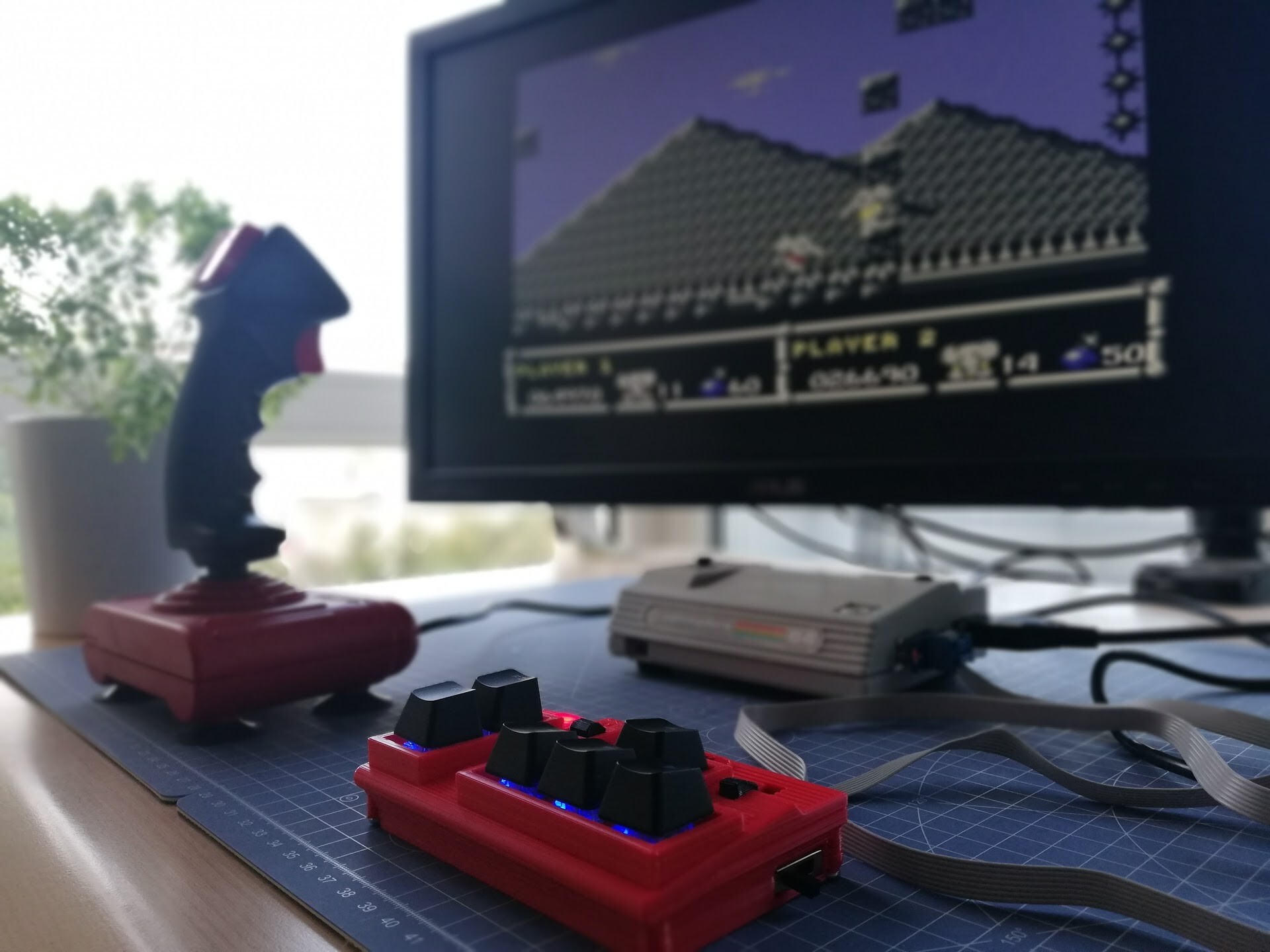
My next attempt was to recreate 8-bit version of Furio Tedeshi's amazing work "Dormant".

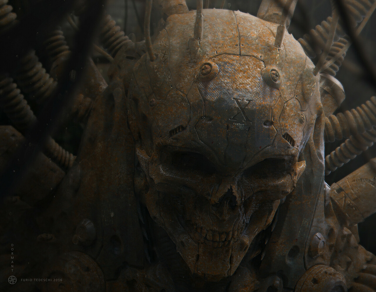
You can check his art by this link: https://www.artstation.com/artwork/z6eYw 

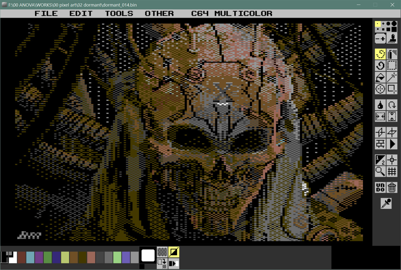
I made another timelapse video:

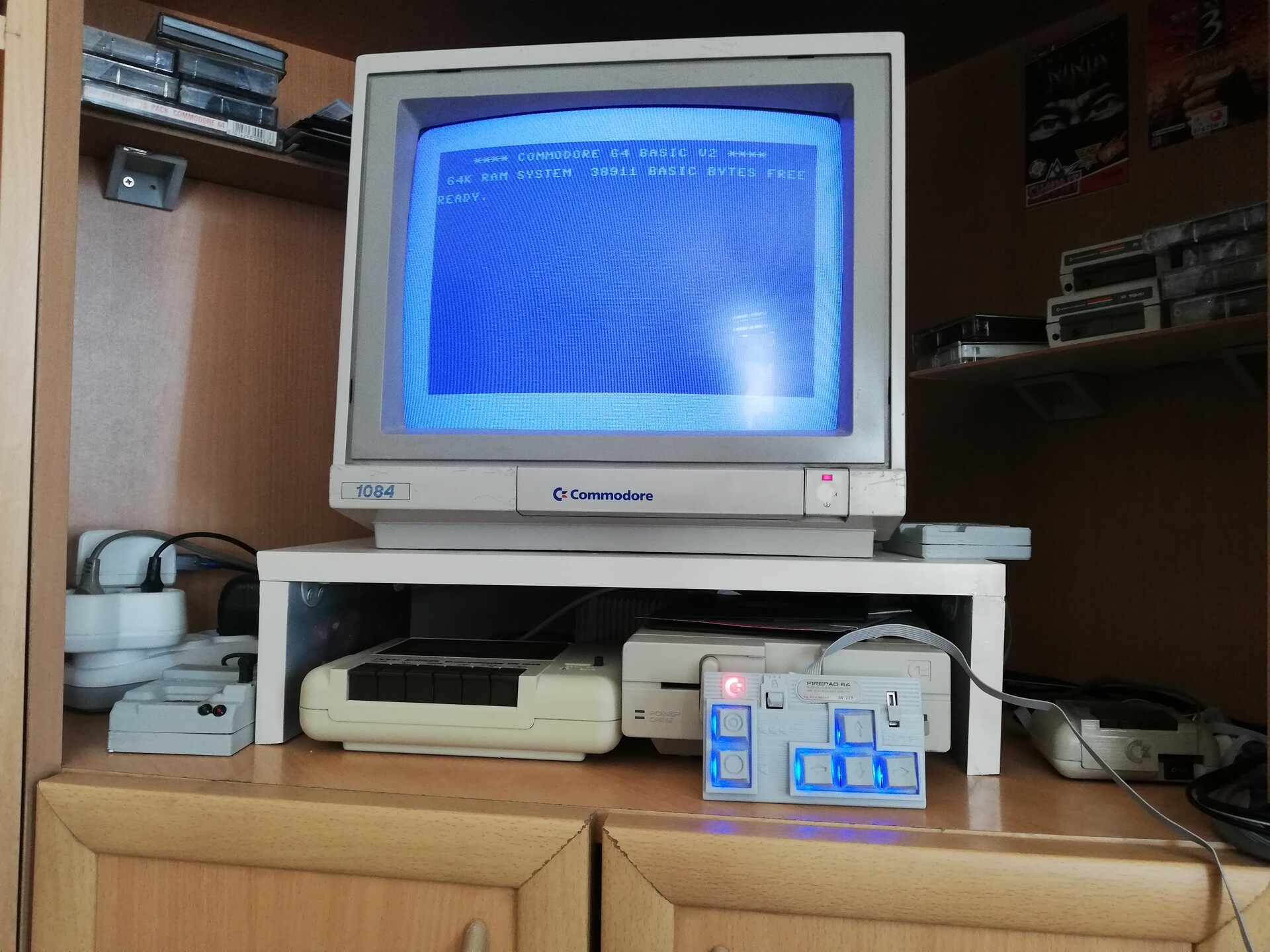
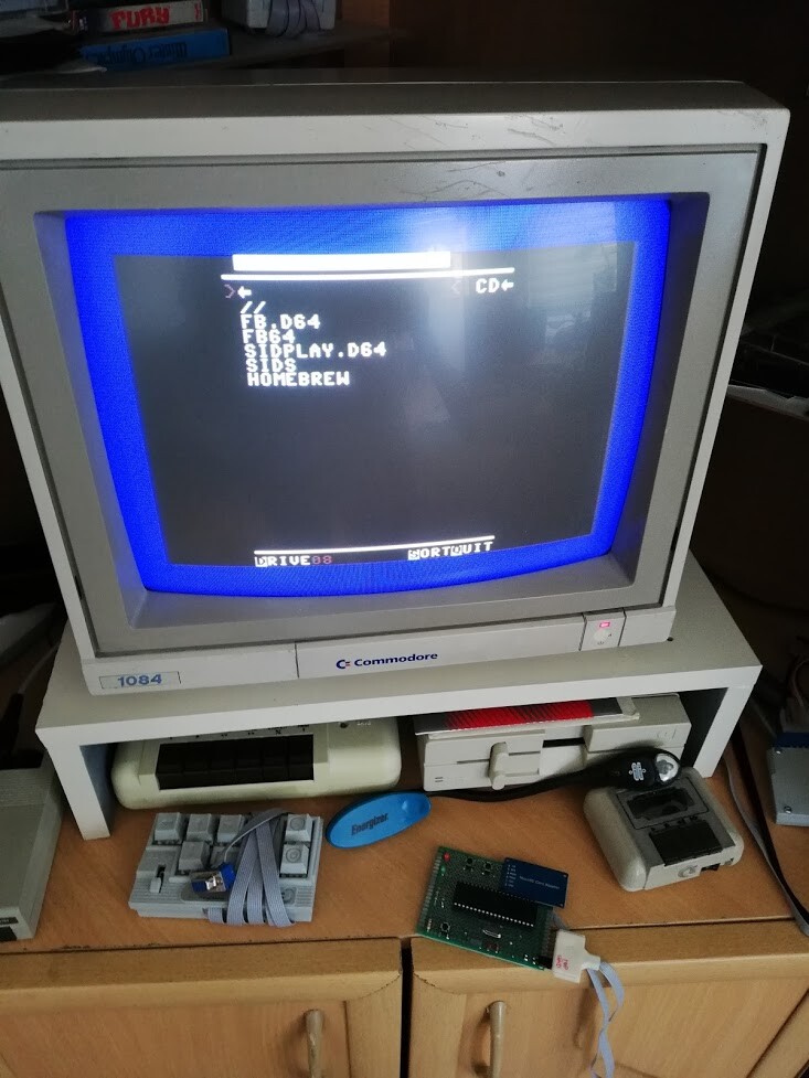
Time to check it on real Commodore 64 and real CRT screen this time!

...and embroidery time!

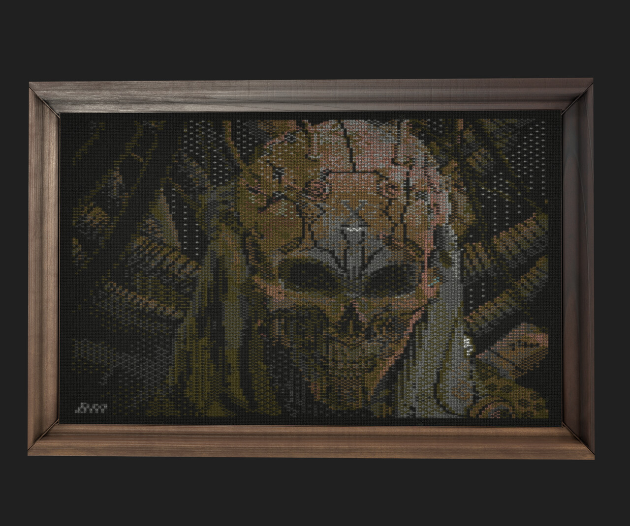
It was real fun making this kind of pixel art by the limitations of 38 years old hardware. Thanks for reading. Cheers!

Portable Commodore 64 - Some Progress

Making Of / 27 May 2020

Hello,

Check this video first!


Previously I made some conceptual design for my portable C64 with cardboard placement.

After finalizing the electronic and mechanic components, I made de rough placement into a cardboard which you can see more details on this blog post.

https://www.artstation.com/blockmind/blog/QlQE/a-proof-of-concept-portable-commodore-64 

This time I designed interior stands to hold all compoenents in a way that made on the cardboard placement. So I measured all compoenents back, and designed holder skeleton stands. These stands will be able to fixed in a planar surface at the ground.

 You can see some progress screenshots from Solidworks.


While designing the stands, I started to 3d print them and try to see if they fit and cables are OK starting from the bottom keypad and analog converter board.


To save space, I tried my best to place all components in 2 or 3 layers.  

So I moved on to the upper part with analog controller.


I made the connections through test solders of the raspberry pi as much as I can, to get rid of using connectors. Because the consume to much of space.  

Next I printed the stand that holds USB controller, Raspberry pi and the Screen.

It fit great!


Only menu navigation buttons set and the battery pack is remained.

And finally I printed the battery and navigation key stands with black PLA this time.


Everything in it's place but they are not fixed.

To fix everything on a wooden plate, first I extracted a bottom surface drawing from Solidworks.


Printed the drawing and checked if it's correctly scaled with the reference dimension on the drawing.

I glued the template to the wooden plate and drilled the holes with a screw (first I printed the mirrored template by mistake!).

And finally fixed!


Look at that screen with CRT Filter! Imho it's almost perfect for  a 800 x 480 pixels screen.

See you on next post!

Creating a Pi1541 with a Pi Zero and Case Design

Making Of / 23 May 2020


Hello,

Previously I made a case design for the Pi1541 standard "hat" circuit to place over Raspberry Pi 3 devices. To see what is a Pi1541 and what it's used for you can check my previous blog entry:

https://www.artstation.com/blockmind/blog/n178/pi1541-case-design-hobby-project 

This time I assembled the electronic part by myself, using a prototyping PCB, by following the instructions on this page:

https://cbm-pi1541.firebaseapp.com/ 

Fİrst I started iwth this circuit diagram.

I made my layout in Excel to place the components onto the prototyping PCB.  

 I also checked the layout with physical items.


After several hours of soldering I completed the circuit (looks like some device from the "Back to the Future". 

...and I tested it out by conencting to my Commodore 64.


Now it's the fun part: the case design.

As usual, I used Solidworks to design the case. I took measures of the existing circuait with calipers and then made the case design by checking the clearences. Here is the modeling timelapse:

I printed the design with my 3d printer and applied to the circuit.


All good except I fotgot the LED holes! 

So I drilled the holes with screw driver.

Nearly ruining the print!

Fİnally better than nothing.

I soldered the LED extension cables.


And it's complete.

Working good as a disk driver on real C64.


See you on next project! Cheers!

SD2IEC Circuit and Case Design

Making Of / 26 April 2020

This weekend I made an SD2IEC circuit with prototyping board and some more components, then I designed and printed a case for it.

SD2IEC is a device that fools Commodore 64 to read / write floppy disk images with an ATMEGA microcontroller. It's not a cycle exact emulation, so it has flows on using on real c64. But it has also a unique type of use by it's nature. Like sid file listing for a Sid player or transfering non-standard files between other C64 devices (for example transfering CRT files to the Easyflash Cartridge).

More about SD2IEC can be found by these links:

https://www.c64-wiki.com/wiki/SD2IEC 

https://sd2iec.de/ 

https://github.com/rkrajnc/sd2iec

There are several revisions and variations of this design but I followed the circuit design on this link: http://pungas.space/blog/index.php?option=com_content&view=article&id=8:build-your-own-sd2iec-with-or-without-pcb-in-english&catid=8&Itemid=102 

I checked the connections on the schematics and made layout by considering the best short connections for all components. Since the hard part here to program the microcontroller with a programmer, I passed this part with the help of a friend who already made the programming for me and sent the microcontroller to me. Thanks to Türker Gürevin!


Next, I made all the soldering according to the schematics with naked coppers and cables.


Nest step vas to make a cable for the IEC plug of the C64. I use and like flex cables for this kind of job.


And for doubling that din cables, I used a on-cable IDC connectors. This way I don't interrupt the flow and also can add parallel connections to the cable.

After completing the soldering and cable preparation, I connected the device to my real C64 and tested it. Works nice!

Playing some sid music from the listed files within the SD2IEC.

So after the electronic part is complete, I made a quick design for the case. By using Solidworks of course!

First I created rough geometry of the electronic part and the buttons etc. to see the critical clearances better while designing the case. I took measures with calipers and entered the dimensions while modeling.


After making the rough object, I completed the case design by making it in 2 parts with a wall thickness. 


Even I don't like it, but this time I designed the case to be glued to stick the parts. Main reason is getting lazy but other reason is, making a case assembly by shrink-fit or screws needs to expand the outer boundry over the borders of the PCB. It means larger case. Since the electronic part doesn't need any maintenance (SD card is accessible from outside) I made it this way.

This is ithe simple button cap design for to use over the tactile buttons:

And finally I exported the files for 3d printing which took around 3 hours total for the whole set.

I'm so happy when the designed material is totally comply with the real object after manufacturing it :)

Top part and the button caps. 

Gluing the parts (arrgh!)

And finally we have the device. I made the 3d printing in a low quaility. But it's better than nothing :)


Copying from SD2IEC to real floppy disk.

So this was a quick project but I was in need of that device because of it's extraordinary nature. It has unlimited capacy for a floppy disk, so you can save as much as "freezes". Freeze is a snapshot from a game or program by dumping the bits on the memory to a disk to load it anytime when you need a break. freezes created by freeze cartridges like Action Replay, Final Cartridge etc.

So SD2IEC took its part on my Retro Corner.

Thanks for your time, I hope you like it.

Cem

Portable Commodore 64 Design with BMC 64 Emulator

Making Of / 21 April 2020


Hello! Check out the video first!


We were playing some Commodore 64 games with my daughter for a while. We are playing with raspberry pi zero which is a cheap hardware and runs BMC64 very smooth which is a Commodore 64 emulator.


I had made some case design for the Pi Zero before. Here is the link:

https://www.artstation.com/blockmind/blog/rRO3/micro-commodore-64-design-and-bmc64-emulator-on-c64-case 

But since it's small but it needed a powersupply to power it up and also a controller is needed to use the device for accessing menus and loading programs or games. By itself, it is just boots. You can do nothing without additional controllers. Also, connecting real C64 joysticks to that case was hard. I had created another gizmo to use it as a joyport.


This time I decided to make a compact, all-in-one system for that device. So, I included:

  • A tactile joystick
  • A chargable battery (1 x 18650)
  • DSub 9 joystick ports
  • Micro to standard USB expansion
  • Mini to Standard HDMI extension
  • And finally an On/Off Switch

I started to solder the ports I needed by connecting the to some prototyping boards.


Raspberry Pi Zero has micro USB and mini HDMI inputs. This makes it harder to connect standart USB devices or standard USB HDMI cables to it. So I made a simple micro USB converter. I made this converter to align with the end of the HDMI port converter piece.


By adding the charge unit and the battery, I gathered all the objects, made a placement on the table to use it as a starter for the case design.

I use Solidworks to make the blockout of components and make the draft case design first.

I advance the design by checkin all clearances and cables with the real object.

When I'm confident that the bottom part is ready, I 3d printed it before finalizing the top part. Because I needed to see that everything will fit, and there is no wrong measurement. Because 3D printing of the top part will take more time.


Everything is at where it's supposed to be.


Then I finished the top part design by just adding minor details.


Finally I made the 3d printing of the top part.


Time to remove the supports.


And close the case.


Lets charge it!

And put a label...


Here are some shots of the final device.


...and some draft renders:


BMC64 Homepage: https://accentual.com/bmc64/ 


Update!

SD card slot was inside the case (on raspberry pi), so when I needed to change the content of the SD card, I needed to open the case by unscrewing.


I used a flex SD card extension to the case by cutting the side wall.


I used some folded foam layer to stabilize the SD card slot.


And finally now it's easy to add remove backup files without opening the case.


A Proof of Concept - Portable Commodore 64

Making Of / 09 April 2020
I'm working on a Portable Commodore (with BMC64 emulator) for a while. Finally made some progress. 

First, I made a list for the electronic components and made a diagram about what I need on this device. Actually I needed everything :) Headphone jack, hdmi out, analog video out, classic joystick connectors etc.


Next I got everything together.


Next I take measurements of the components and made a sketch of case design with Solidworks.


There were too many boards, components, speaker and cables. I wasn't sure if the case will hold up everything.

I virtually made a placement.


Then, I simpllified it and converted to sheet metal desidn and printed the unfold surfaces as templates.


I cut some cardboards by this templates and taped the faces. 


I put every electronic components inside (I used paper to prevent electrical shortcuts :) ) and voila! It holds the components and I can move on polishing the case design by making fixing lugs and 3d print it finally :)


And this is the portable C64 up and running. I hope I finish the plastic part soon :)


Tapecart SD Case Design

Making Of / 04 February 2020

I know this is not an "art" but I love the process of this kind of "homemade" products. 

TapeCart is another retro device. which is developed for Commodore 64 to flash instant data to Commodore's memory by datasette port. This port was used to load programs or games by tape cassettes through devices named as "datasettes". But tape reading process was taking too much time more than 10 minutes sometimes to load just one level of a game.

This uses same interface but by an arduino it gets rid of the motor and tape waiting constraints. You can find additional information by this links:

This case is designed for the PCB design of Tapecart SD device that made by Metallic.

Tapecart SD Project page:

https://github.com/KimJorgensen/tapecart

Tapecart SD device by Metallic (Turkish):

https://www.commodore.gen.tr/forum/index.php?topic=17763.0

https://www.commodore.gen.tr/forum/index.php?topic=17821.0

Anyway, this is a DIY project but I bought this device from another person that assembles and I love it. Then I decided to design and print a case for it.

This is the modeling timelapse of the case design. First I'm modeling the blockout of the electronic part by taking measurements by calipers. This is vital to see the places where inside clearance is needed. Then I make a shell over it.


Some sketch-like renders:


After modeling, I 3d printed the parts with my Ender 3 printer and finally I make the assembly by 4 screws. I fits like a charm :)


PCB board of the device I made the case for is designed by a Turkish friend (Metallic). He didn't share the PCB yet, but if he will, I will update the page.

My 3d model is available by this link: https://www.thingiverse.com/thing:4145118 

Micro Commodore 64 Design and BMC64 Emulator on C64 Case

Making Of / 07 September 2019

BMC 64 is a Commodore 64 emulator created by Randy Rossi. It runs on Raspberry Pi devices and bypass the OS and boots very fast. 

I used this emulator as two ways:

1. in a real C64 case to use it like an old C64 


2. Using the emulator's lite version on tiny Raspberry Pi Zero device and design a case for it


1. Using the emulator in a spare C64 case


First, I embeded one of BMC64 installed Raspberry Pi 3A+ into an empty Commodore 64 Case. It uses real C64 keyboard as an input and also you can connect real C64 joysticks by GPIO pins and a CRT monitor by analog video and audio outputs (HDMI also supported).

I quickly designed some port adapters for the empty C64 case and 3d printed them.

This is video port for the analog video and audio jacks and also the HDMI output. I soldered a 3.5mm jack for the analog outputs and an HDMI cable for the HDMI output.


Next, I made a temporary placement for Raspberry Pi 3A+.

Then,  I placed joystick ports that I made by prototyping board which connected to the GPIO pins, and finally a powerbank board to make this chargable.

I used an Arduino Pro Micro clone to make the C64 keyboard accessible through USB ports of the Raspberry Pi. So emulator will recognize keyboard as input (please see links section at the end of the blog post).  


I used an old Cell Phone battery to make this device chargeble by the spare charge circuit that I keep from a malfunctioned powerbank. And printed an holder for the circuit.

Finally added joystick ports and an On/Off switch. Then I stabilized (!) whole system with paper tape (!) and closed the case.


It works even cordless!!!

Joystick ports also powers up my Firepad 64's light and autofire function! (Firepad 64 is an arrow key based joystick replacement that I made before, check the links).

After a while I made a DC input for powering the device.


Works like a charm!


2. Making a Micro C64


BMC64 emulator also has a lite version which is designed for tiny Raspberry Pi Zero devices.  It also supports real joystick connection, HDMI connection and keyboard support.

I made a 70mm x 38mm case design for this device to have it a C64 look.


3d printed it and placed the device into by adding a LED light that turns on when powered.


BMC64 Lite is complete by connecting an HDMI cable, a wireless receiver for keyboard and a USB cable for powering the Raspberry Pi Zero up.

It's very tiny for me to paint in detail but I give it a try to combine some of my colors to match a real C64 colors at the end.


I made the keyboard part demountable to use the GPIO pins beneath to connect read joysticks to the device.

Here is the real joystick connection:


And finally it can be connected to a TV by using the USB port of the TV as a power source to run the emulator.

Very portable solution :)


Thanks for reading this photo-dominant blog post.


Those are the links that may be useful:

BMC64 Homepage: https://accentual.com/bmc64/ 

BMC64 Lite Homepage: https://accentual.com/bmc64-lite/

BMC64 Github: https://github.com/randyrossi/bmc64 

Arduino Project for Keyboard Connection: https://github.com/mcgurk/Arduino-USB-HID-RetroJoystickAdapter/tree/master/C64_keyboard 

My facebook post about the C64 case integration: https://www.facebook.com/groups/commodoresixtyfour/permalink/10156140173577172/ 

3D model files for BMC64 Zero Case: https://www.thingiverse.com/thing:3848621

FirePad64 - Production for Friends

Making Of / 24 July 2019

I made 16 copies of the project for distribution to the friends. They will be testing and reviewing the prototypes for feedback. 

I wanted to share some photo-details on that small mass production event.

Component assembly and cabling photos:

All 3d printing took 186 hours total (nearly two weeks).


These are the custom cable connector cases that I made for this product.


This photos show the LED and autofire testing on breadboards.

Finally, after all testing, all of them ready to be shipped.