Hello,
Previously I made a case design for the Pi1541 standard "hat" circuit to place over Raspberry Pi 3 devices. To see what is a Pi1541 and what it's used for you can check my previous blog entry:
https://www.artstation.com/blockmind/blog/n178/pi1541-case-design-hobby-project
This time I assembled the electronic part by myself, using a prototyping PCB, by following the instructions on this page:
https://cbm-pi1541.firebaseapp.com/
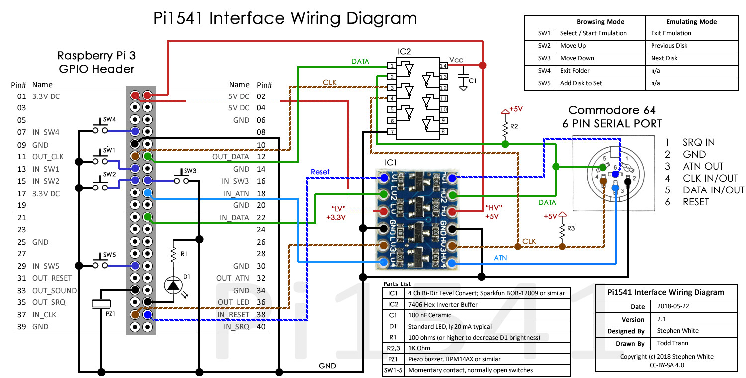
Fİrst I started iwth this circuit diagram.
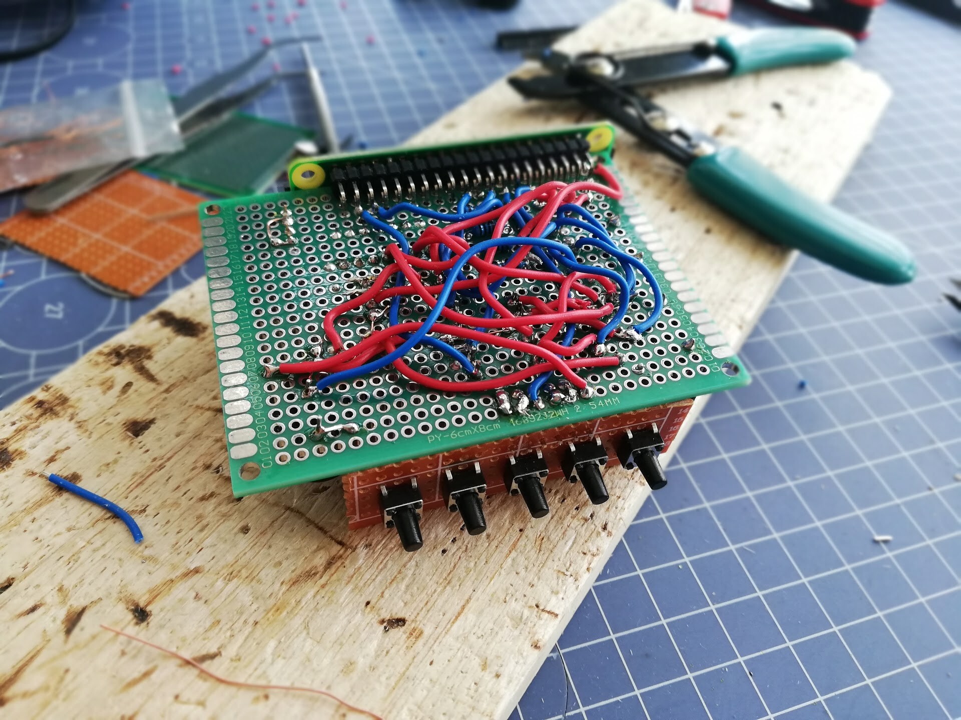
I made my layout in Excel to place the components onto the prototyping PCB.

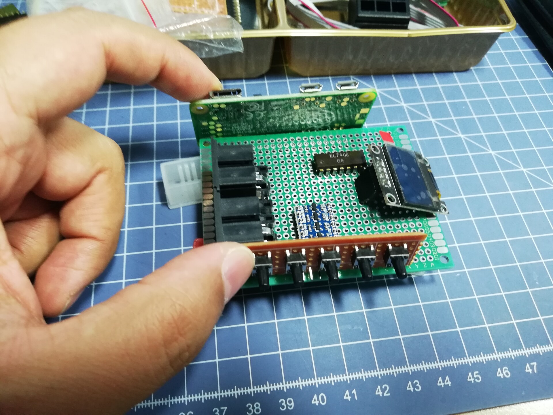
I also checked the layout with physical items.
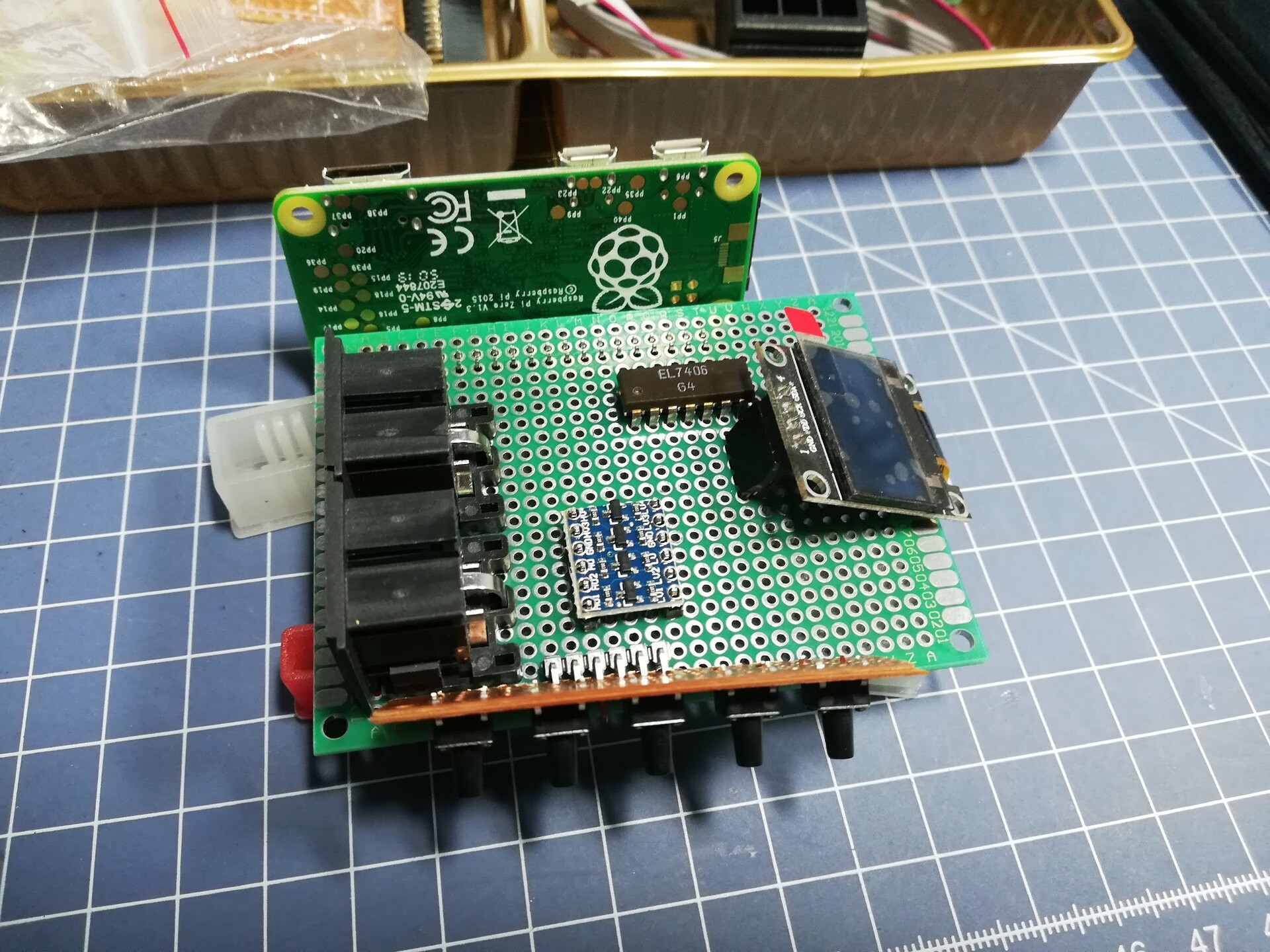
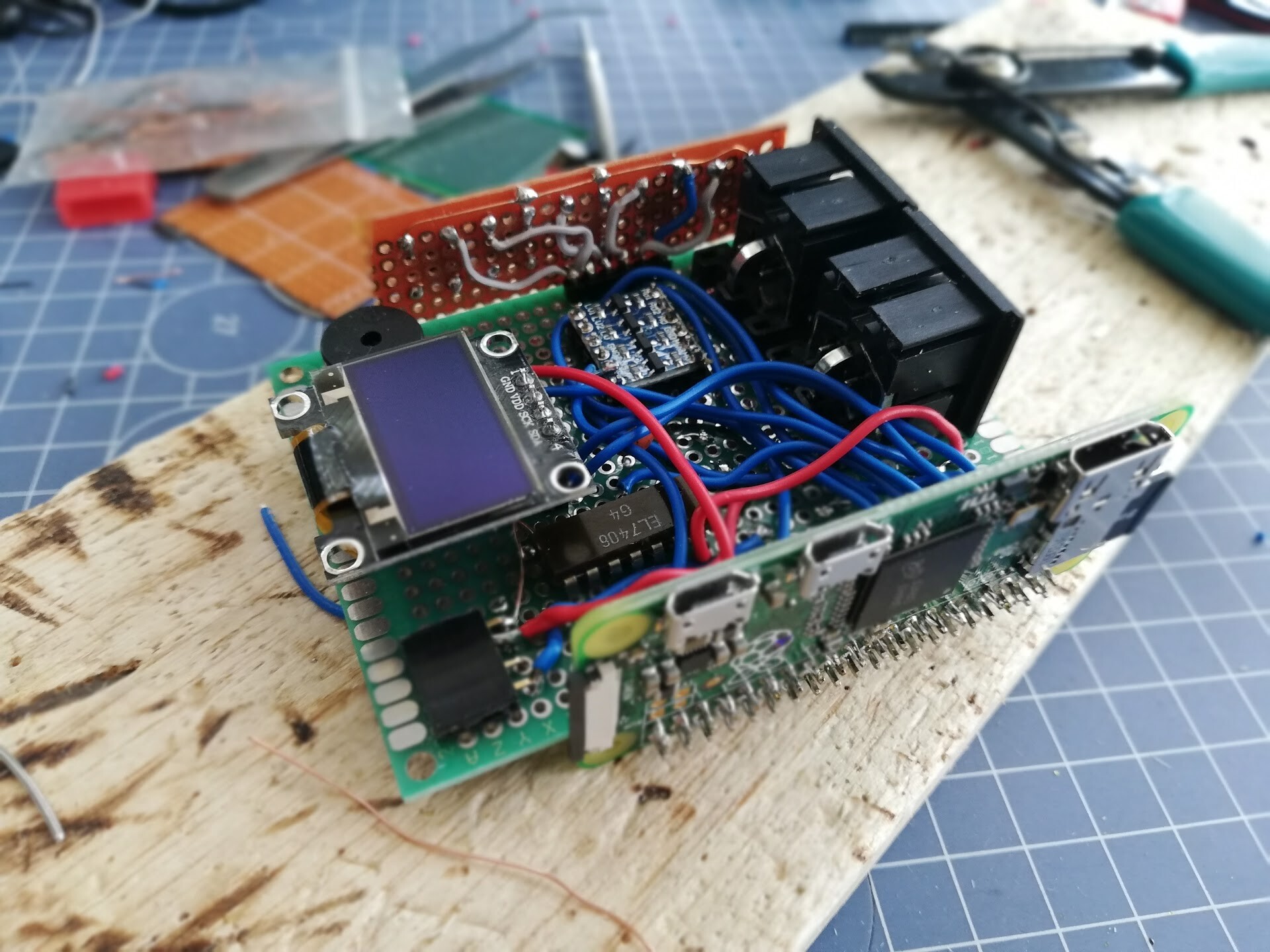
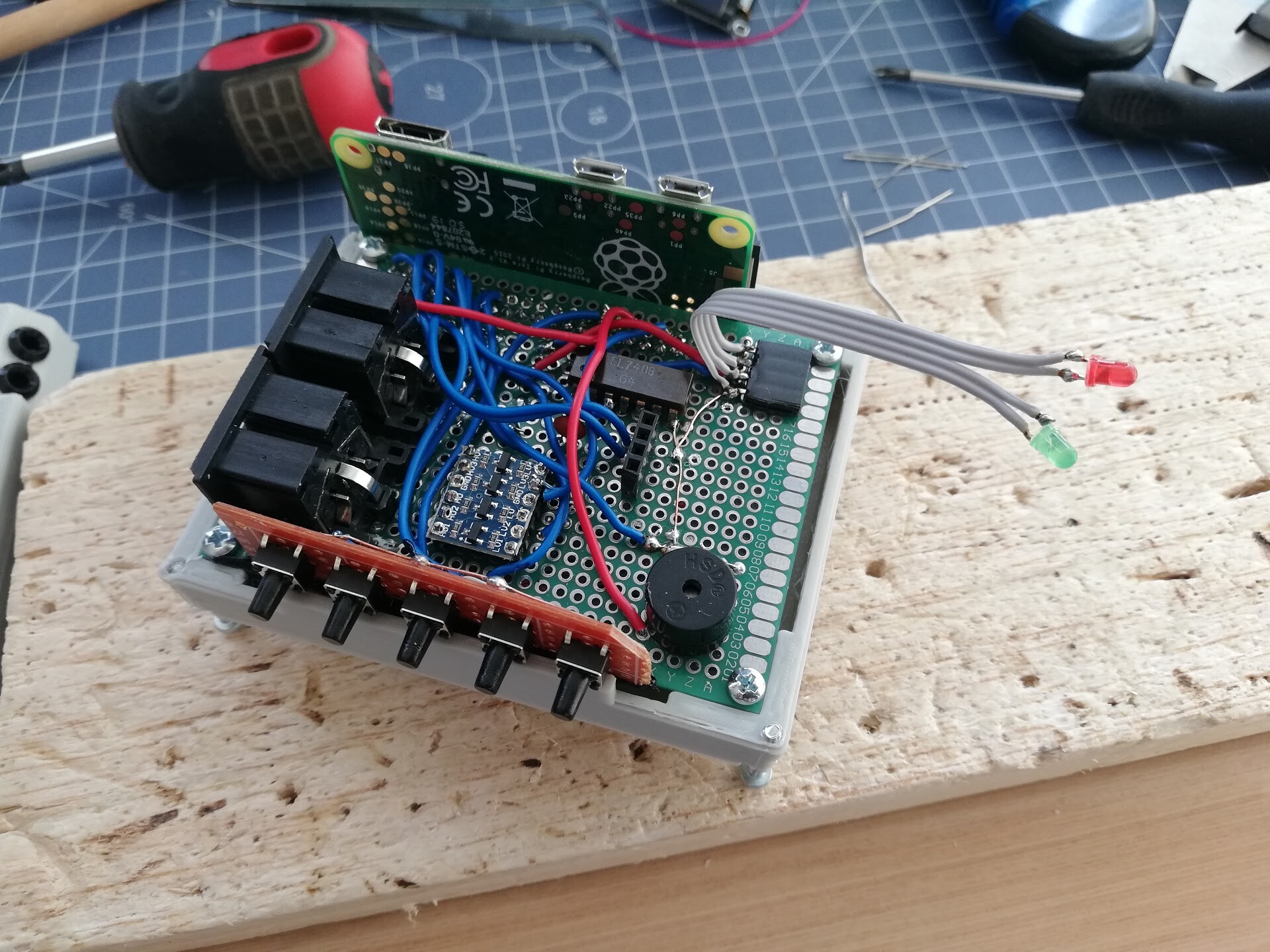
After several hours of soldering I completed the circuit (looks like some device from the "Back to the Future".
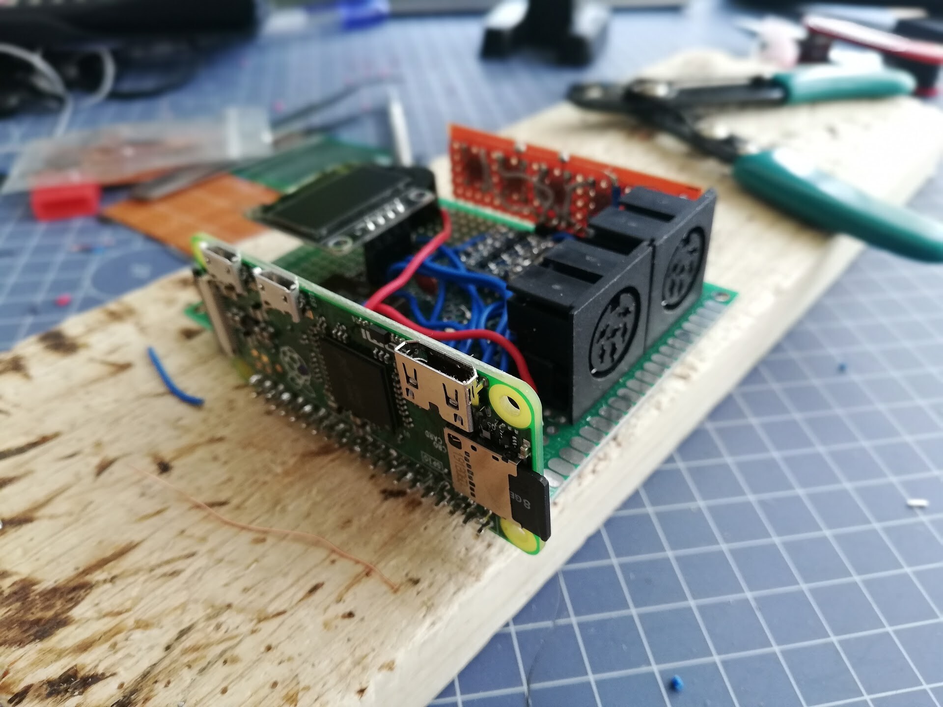


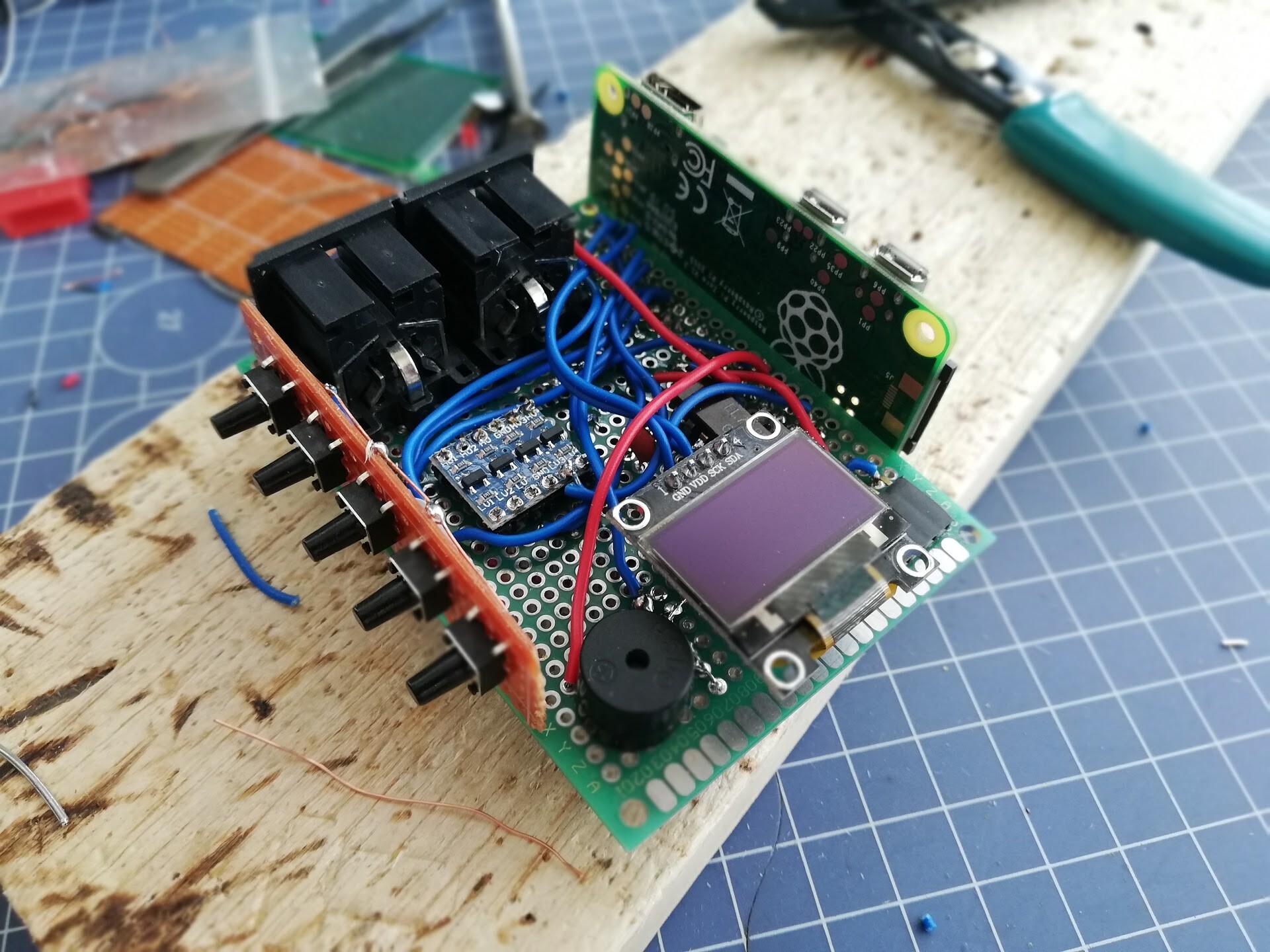
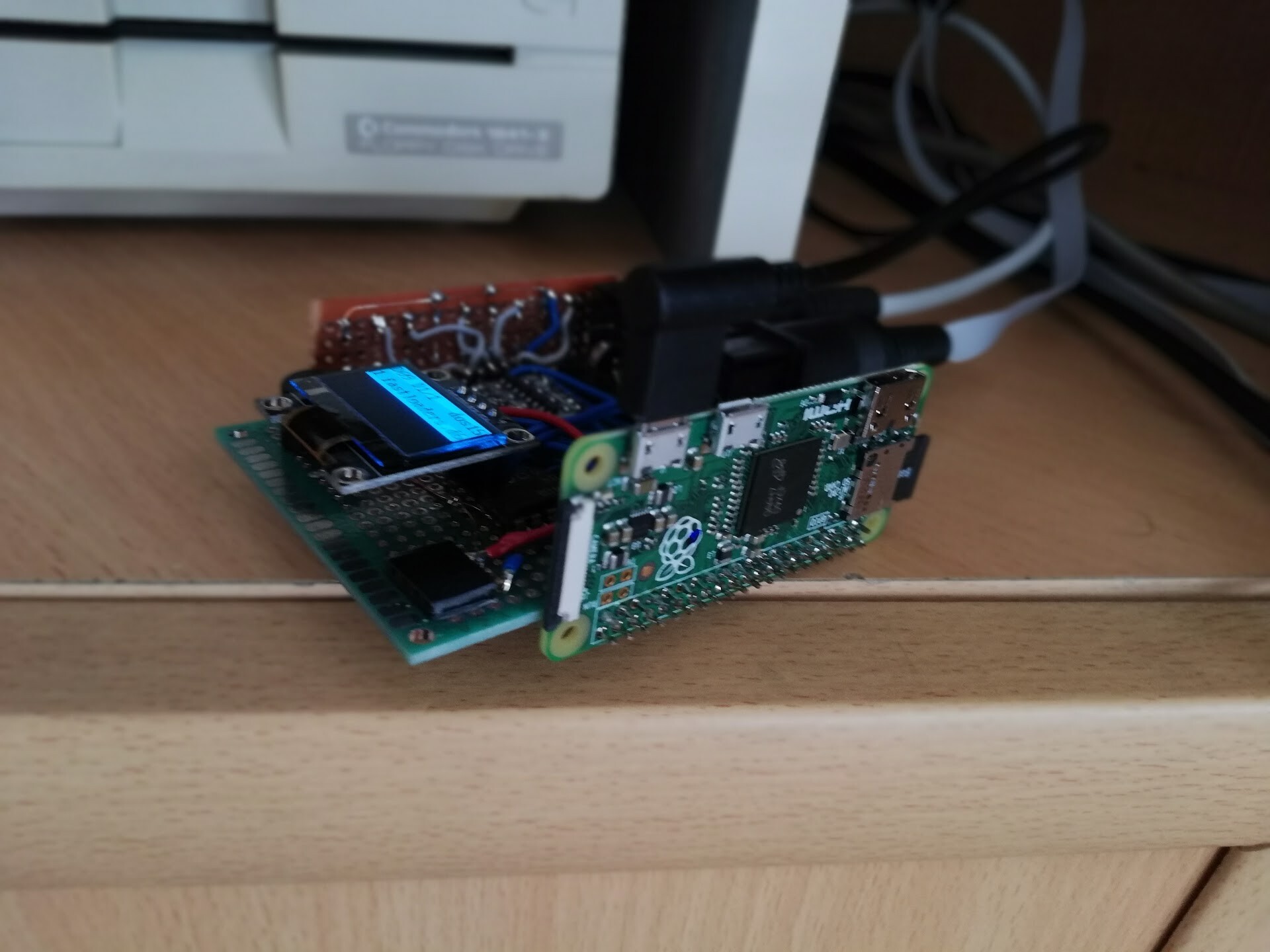
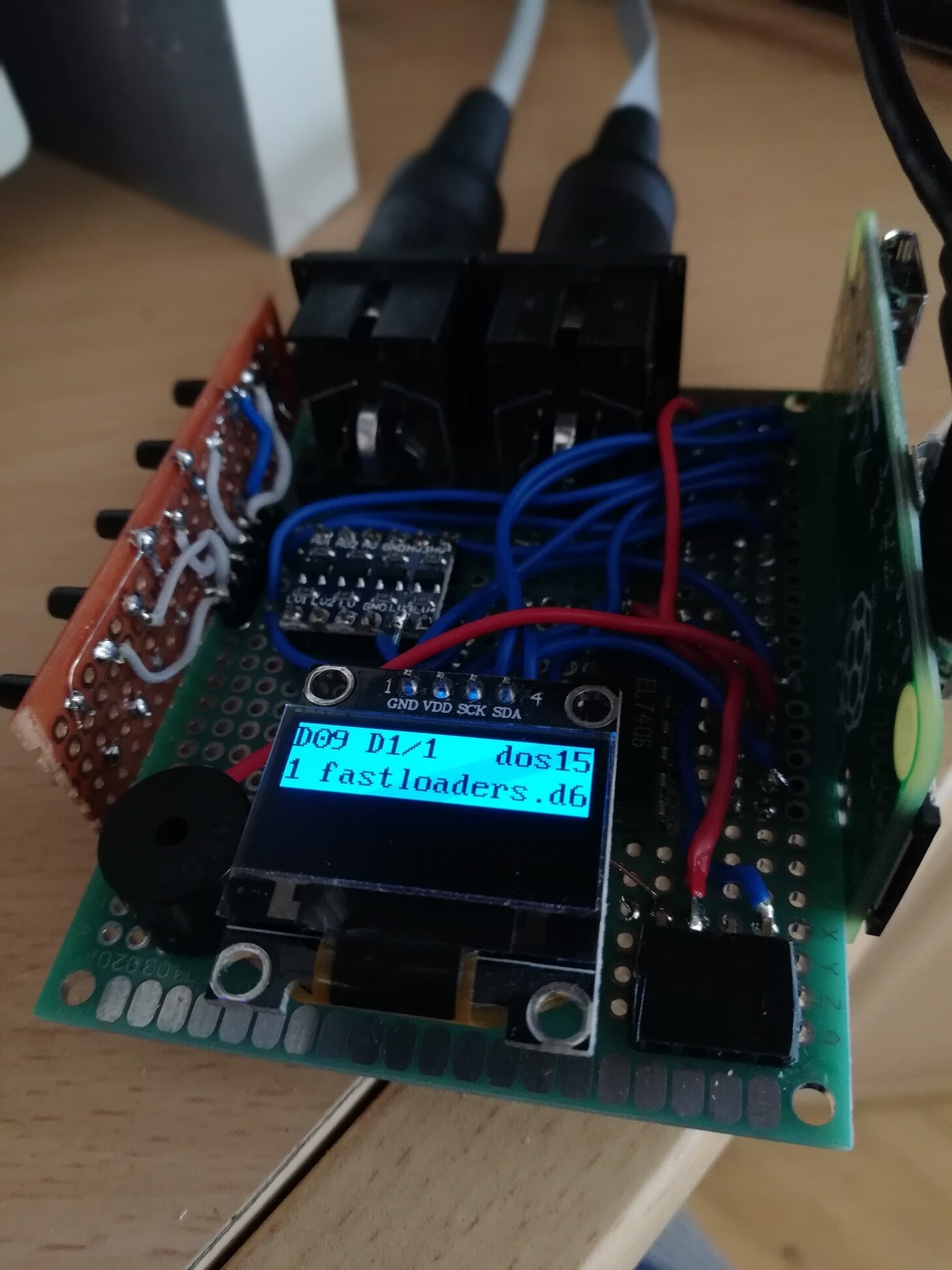
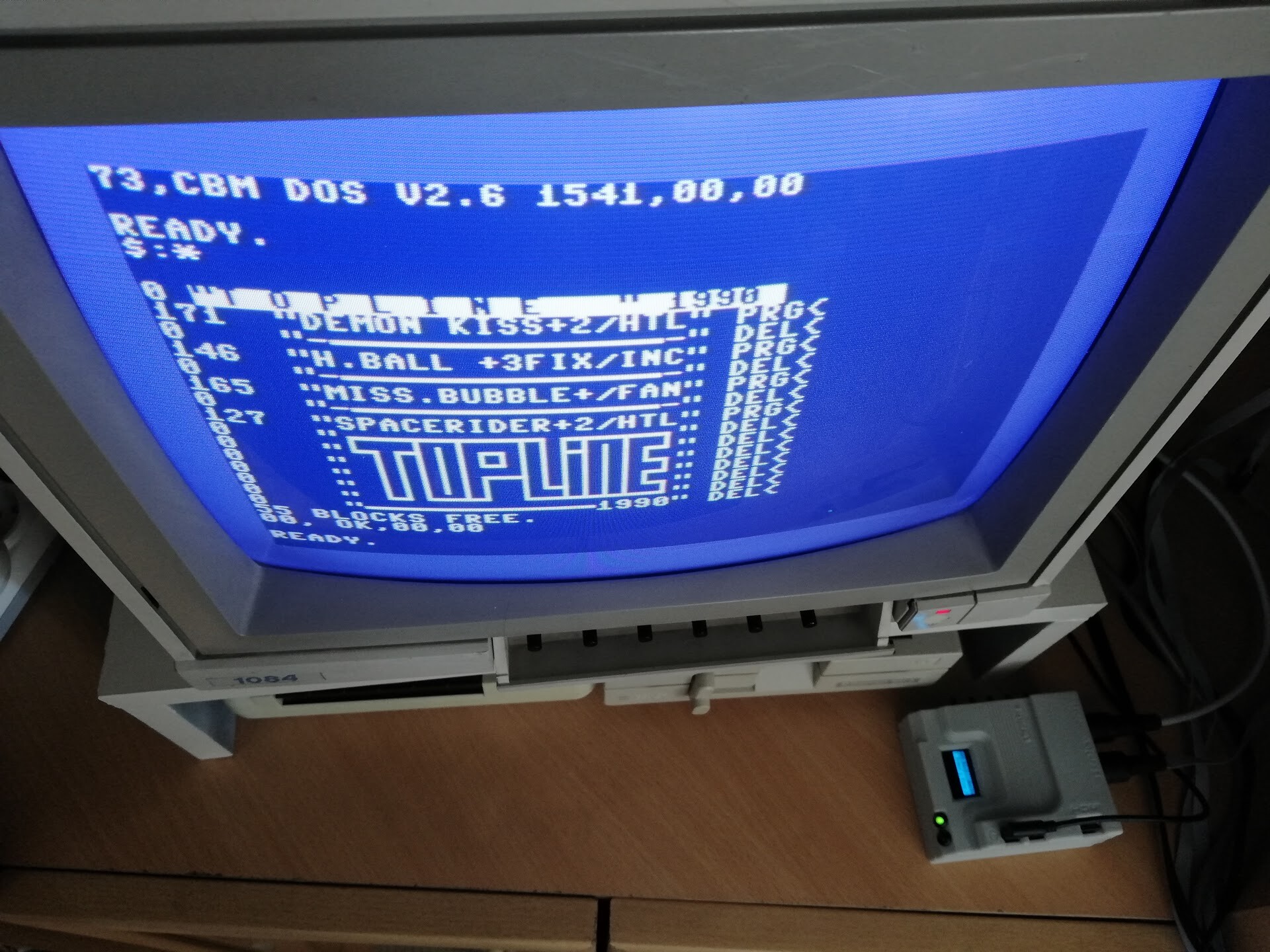
...and I tested it out by conencting to my Commodore 64.
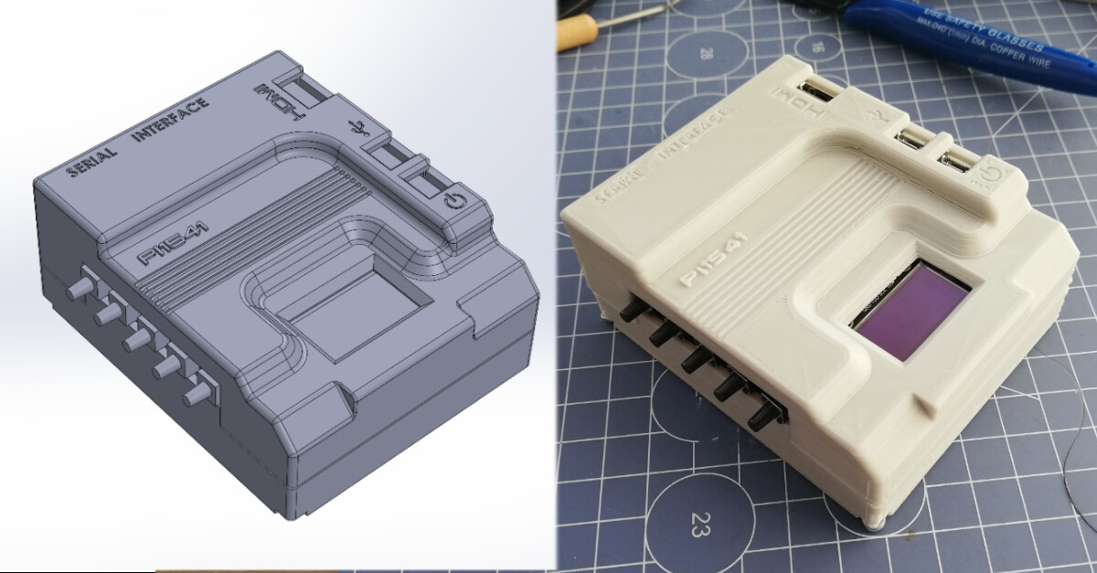
Now it's the fun part: the case design.
As usual, I used Solidworks to design the case. I took measures of the existing circuait with calipers and then made the case design by checking the clearences. Here is the modeling timelapse:
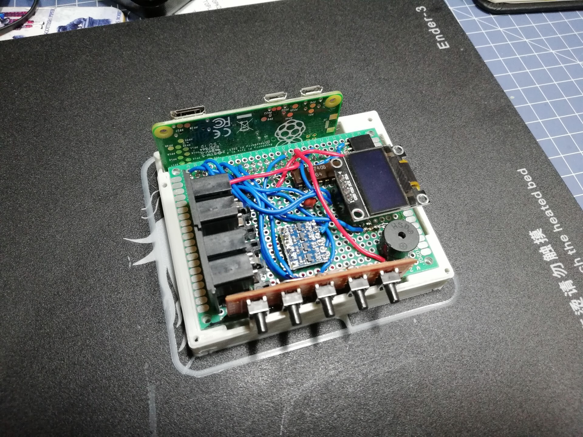
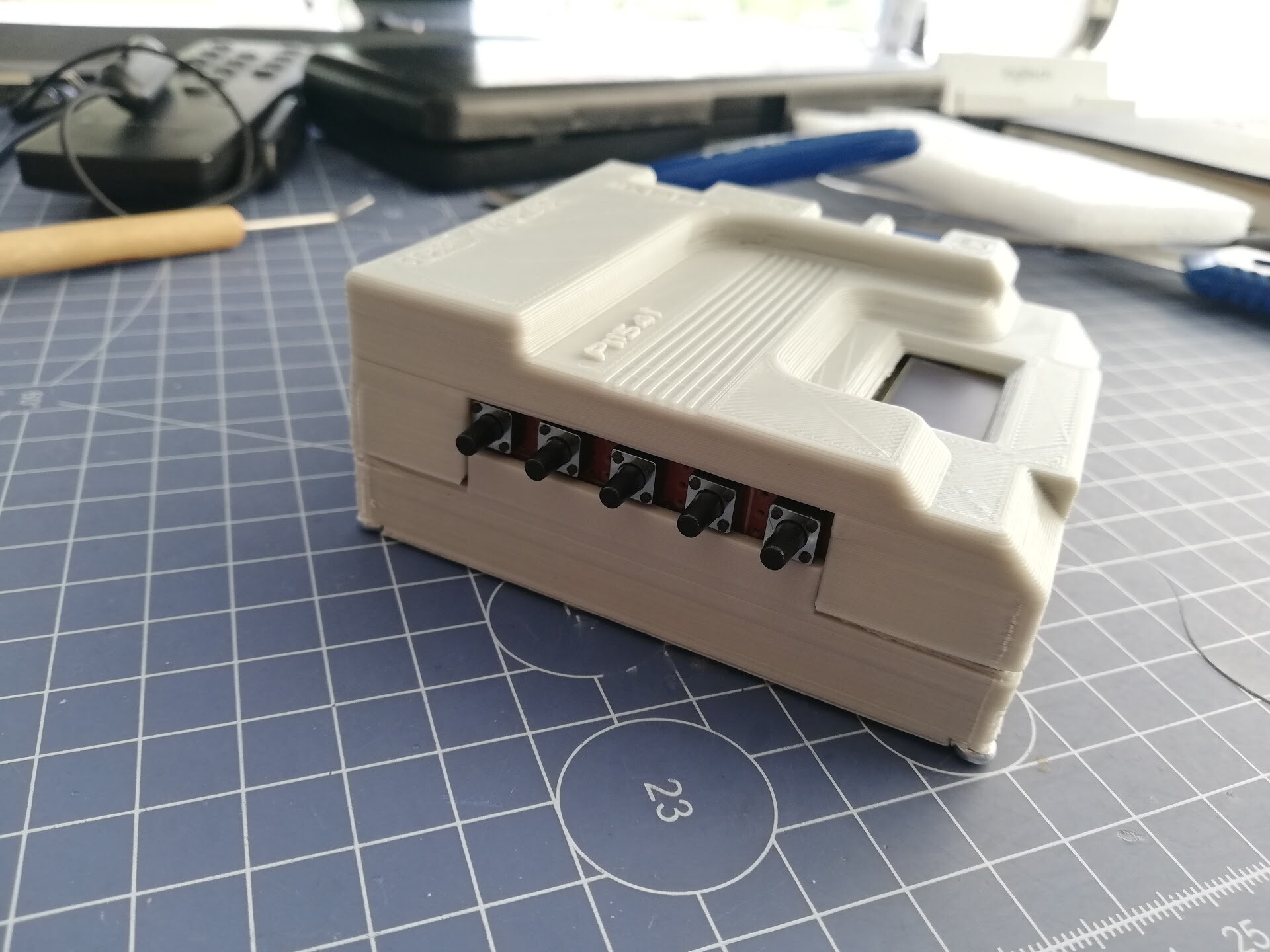
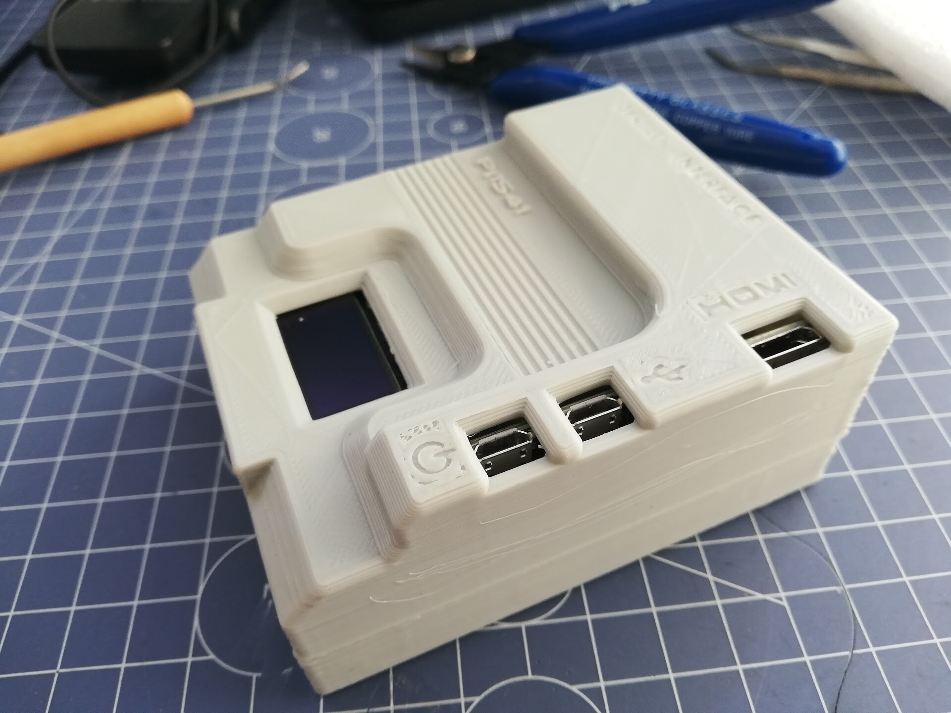
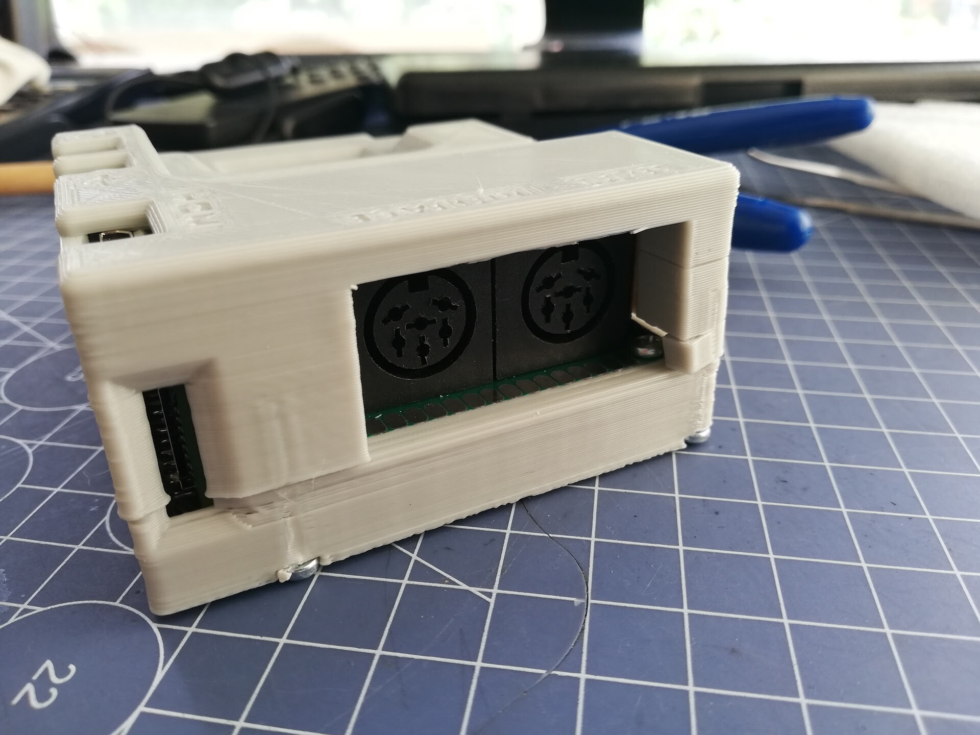
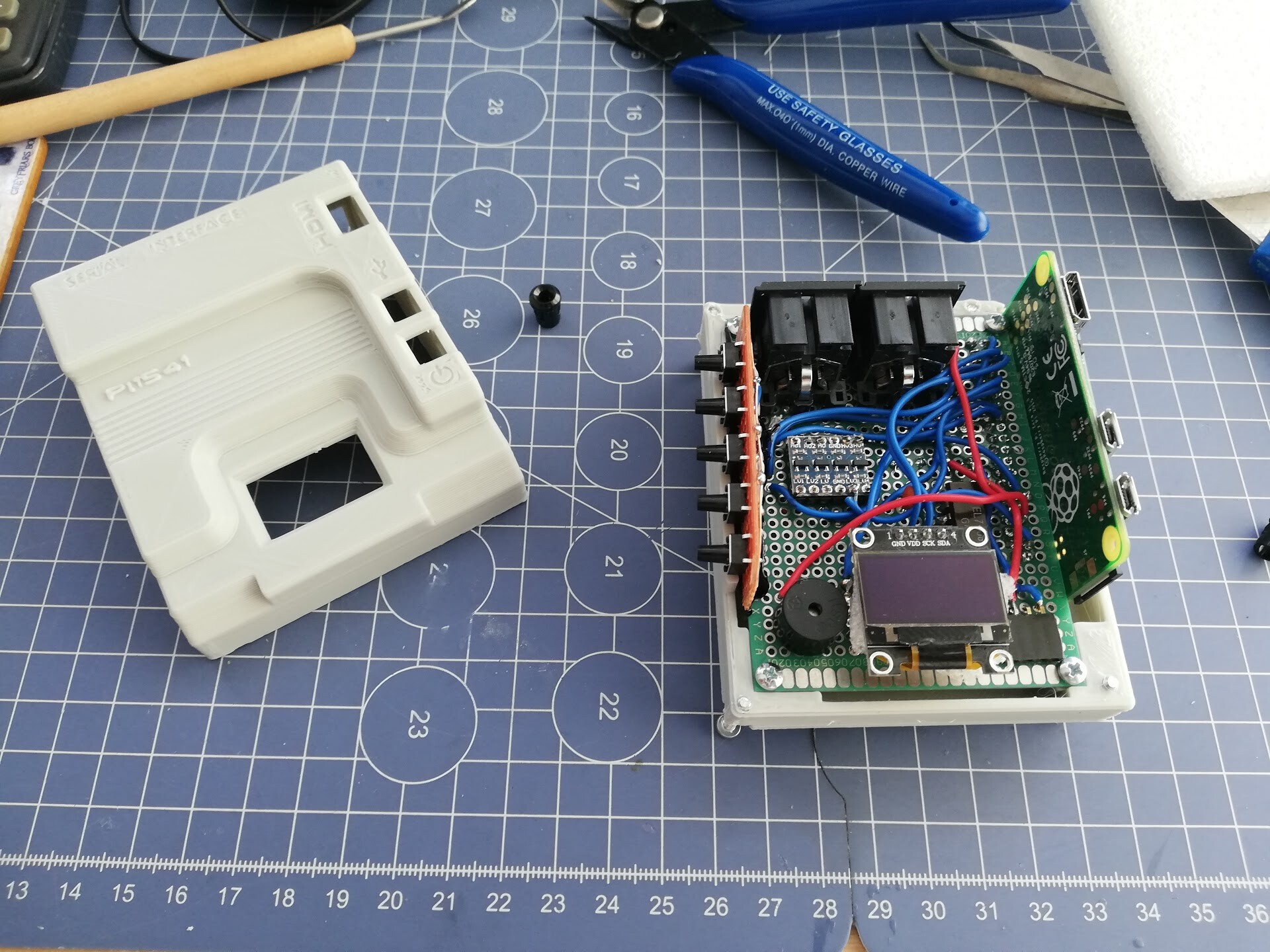
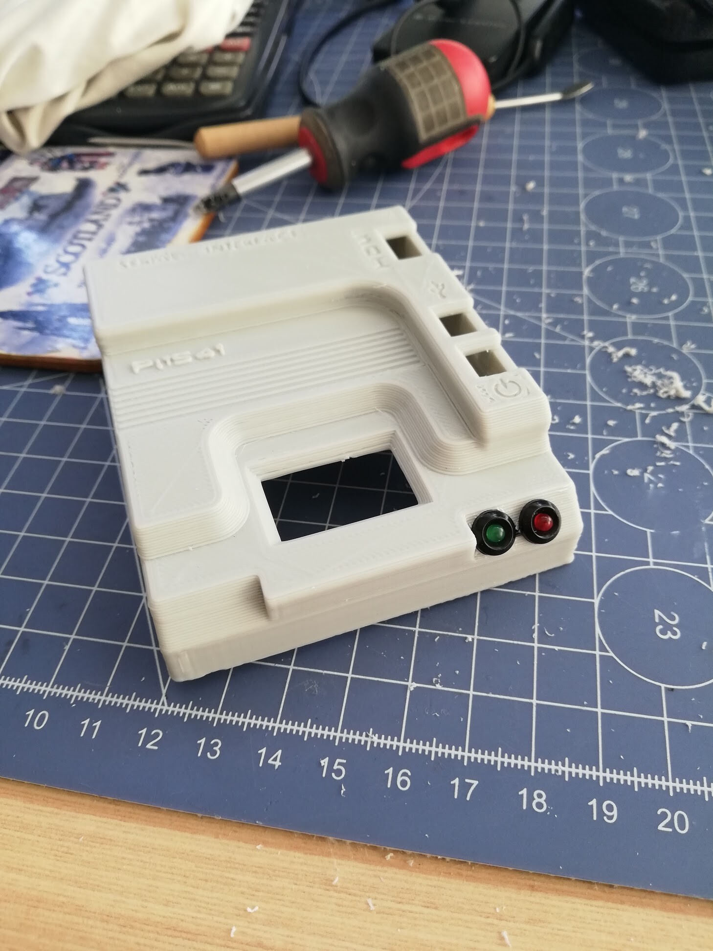
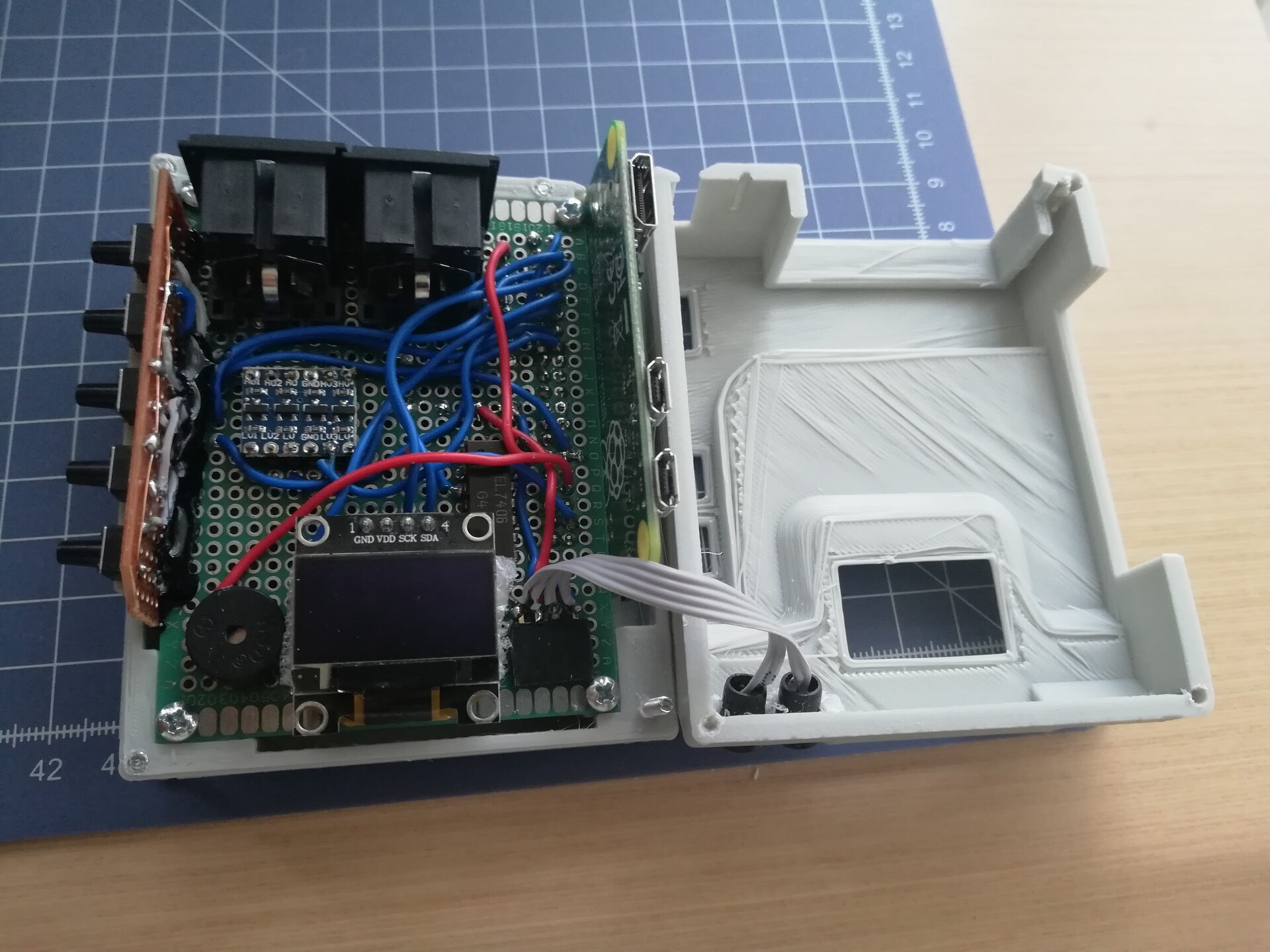
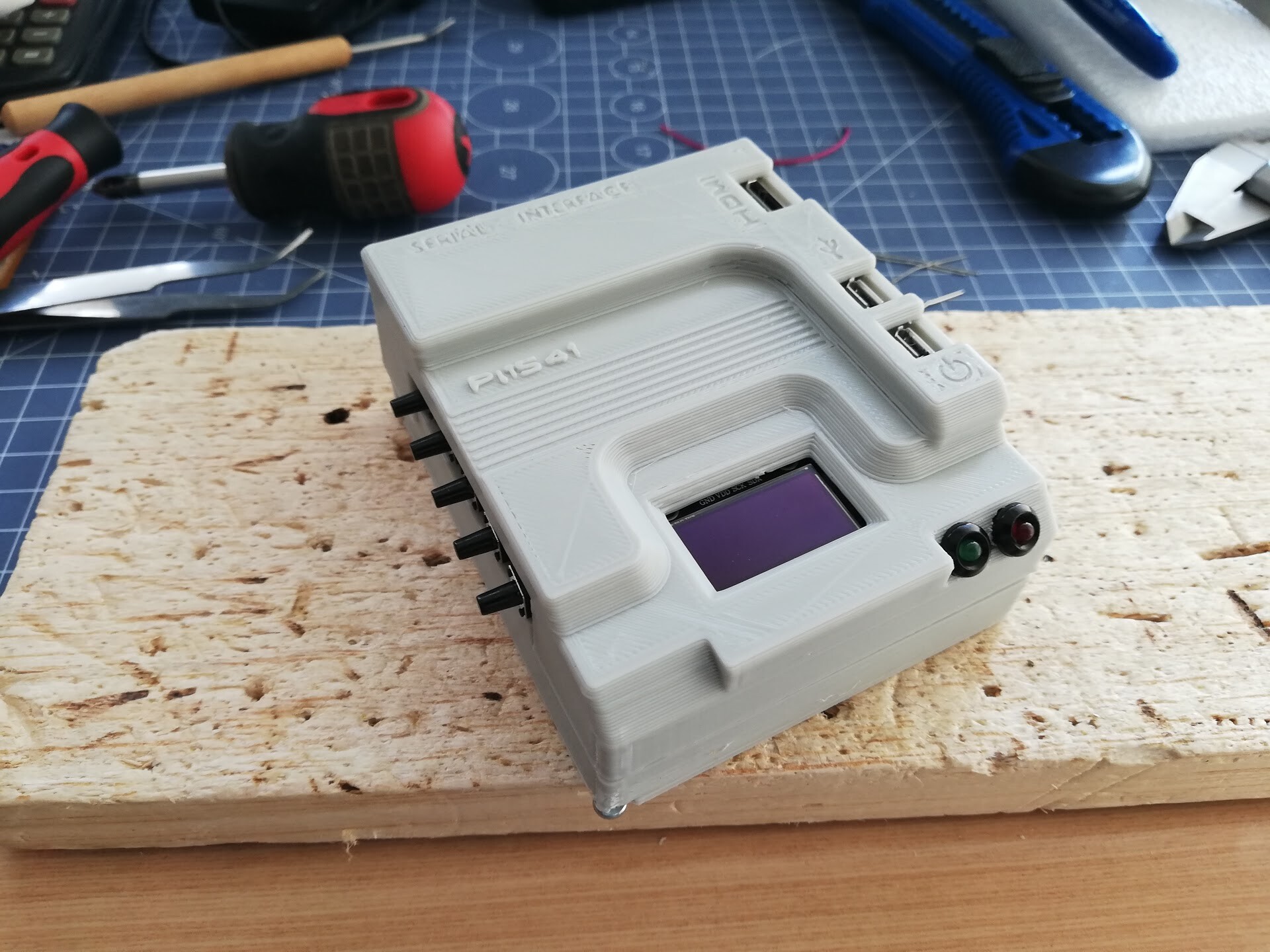
I printed the design with my 3d printer and applied to the circuit.
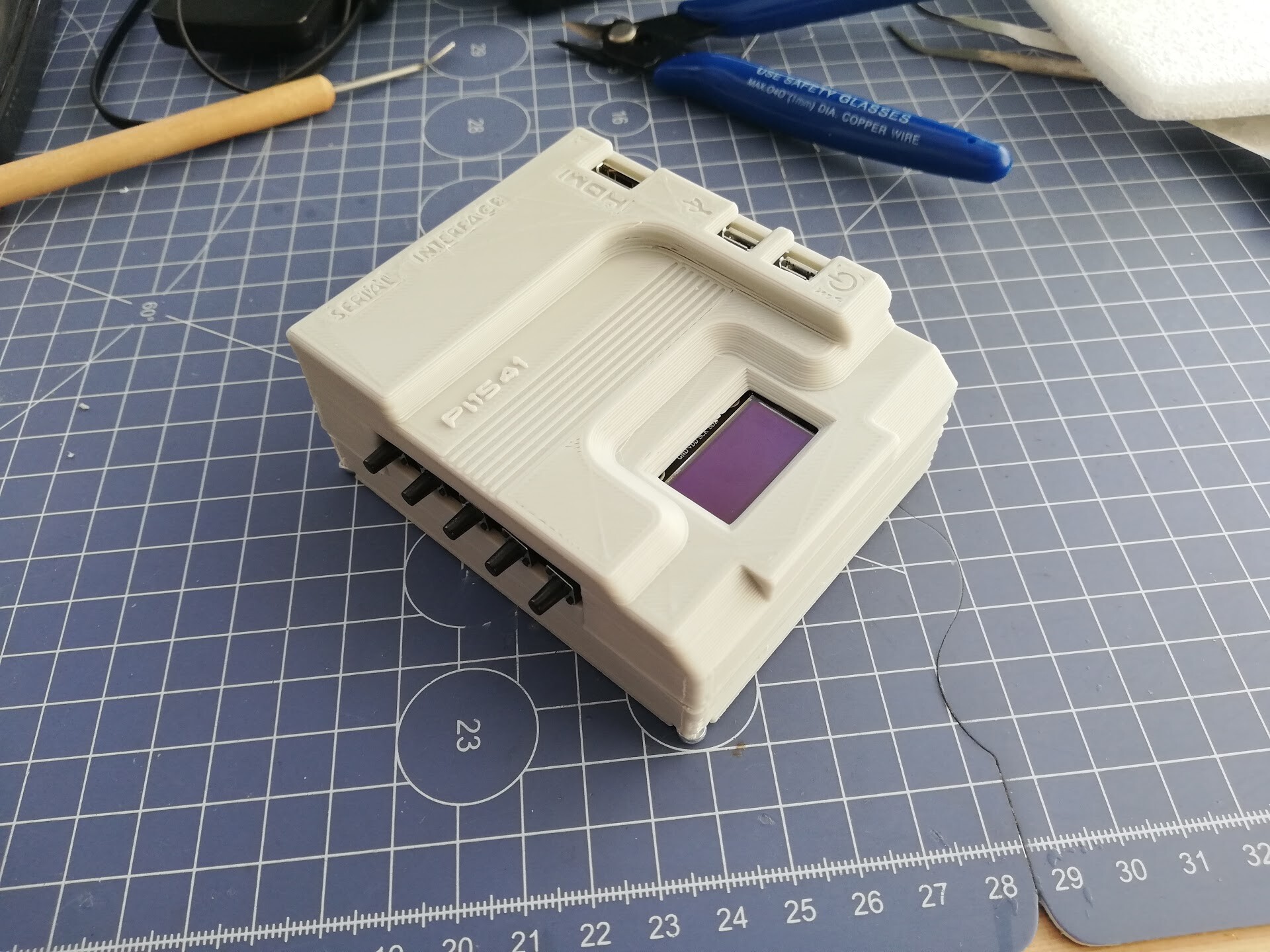
All good except I fotgot the LED holes!
So I drilled the holes with screw driver.
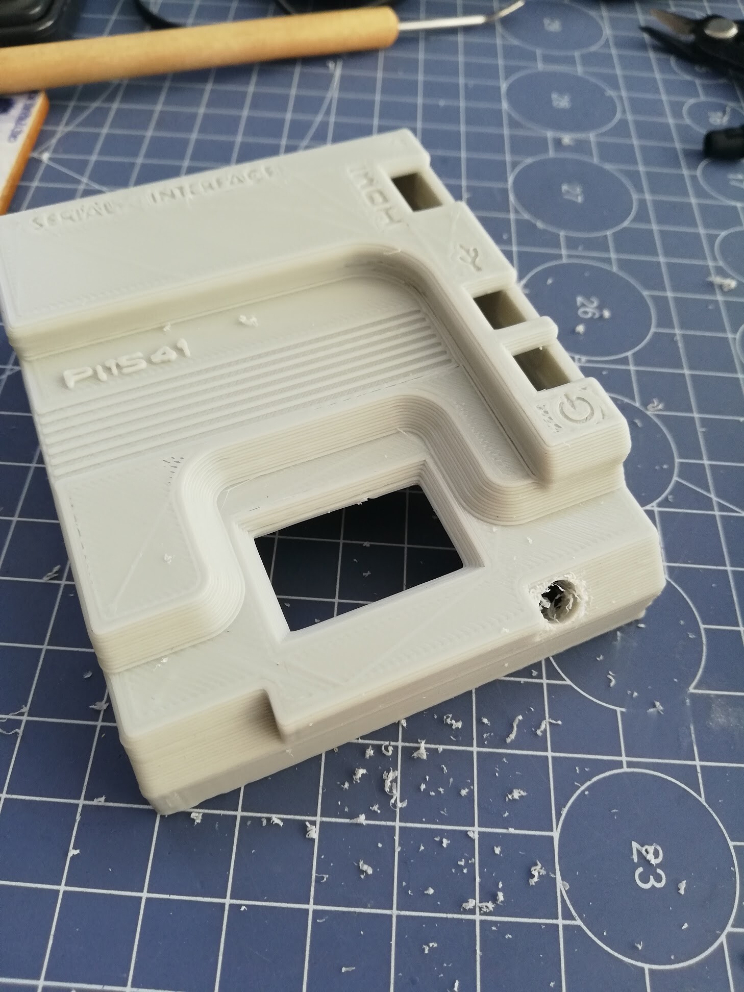
Nearly ruining the print!
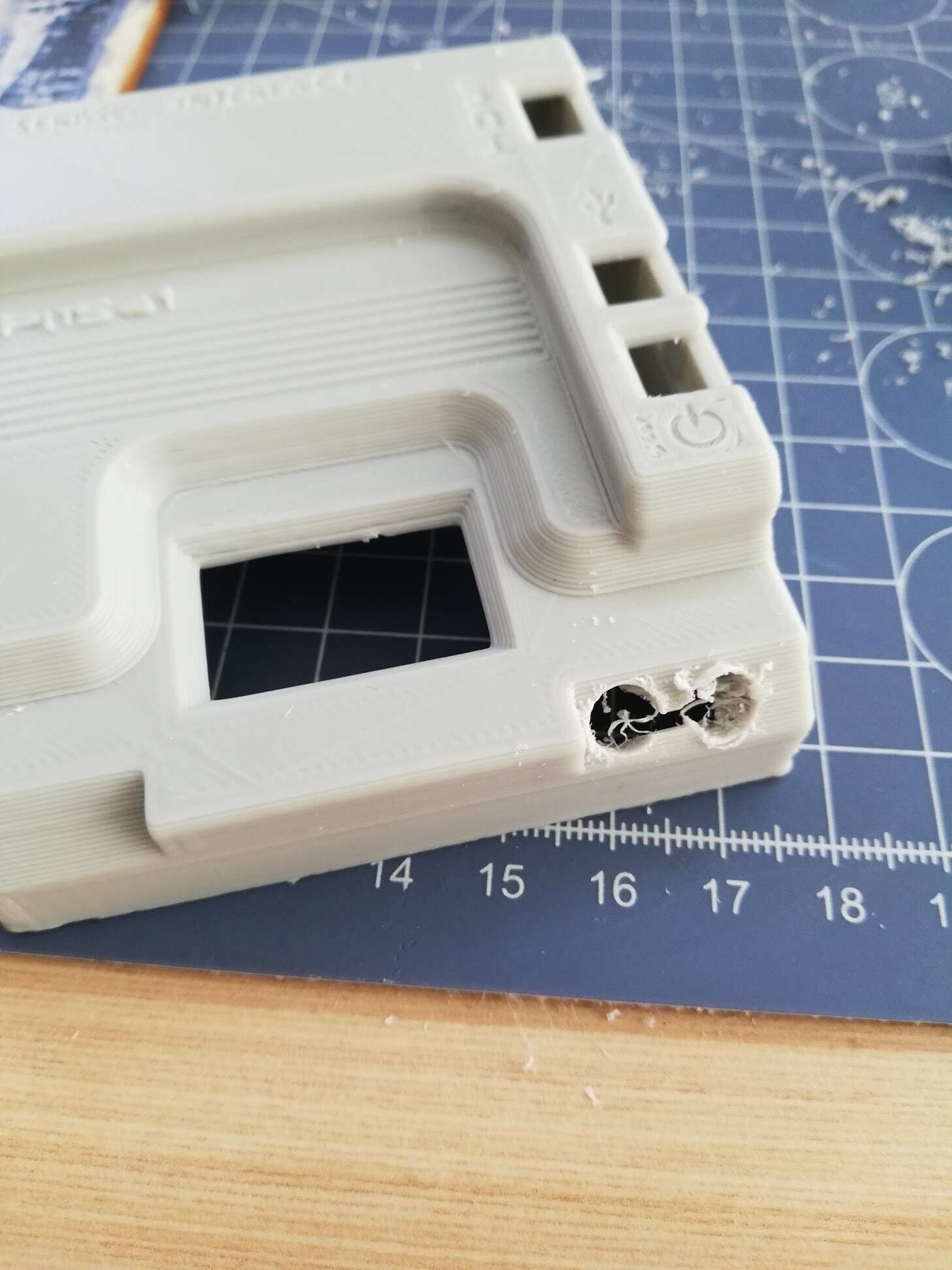
Fİnally better than nothing.
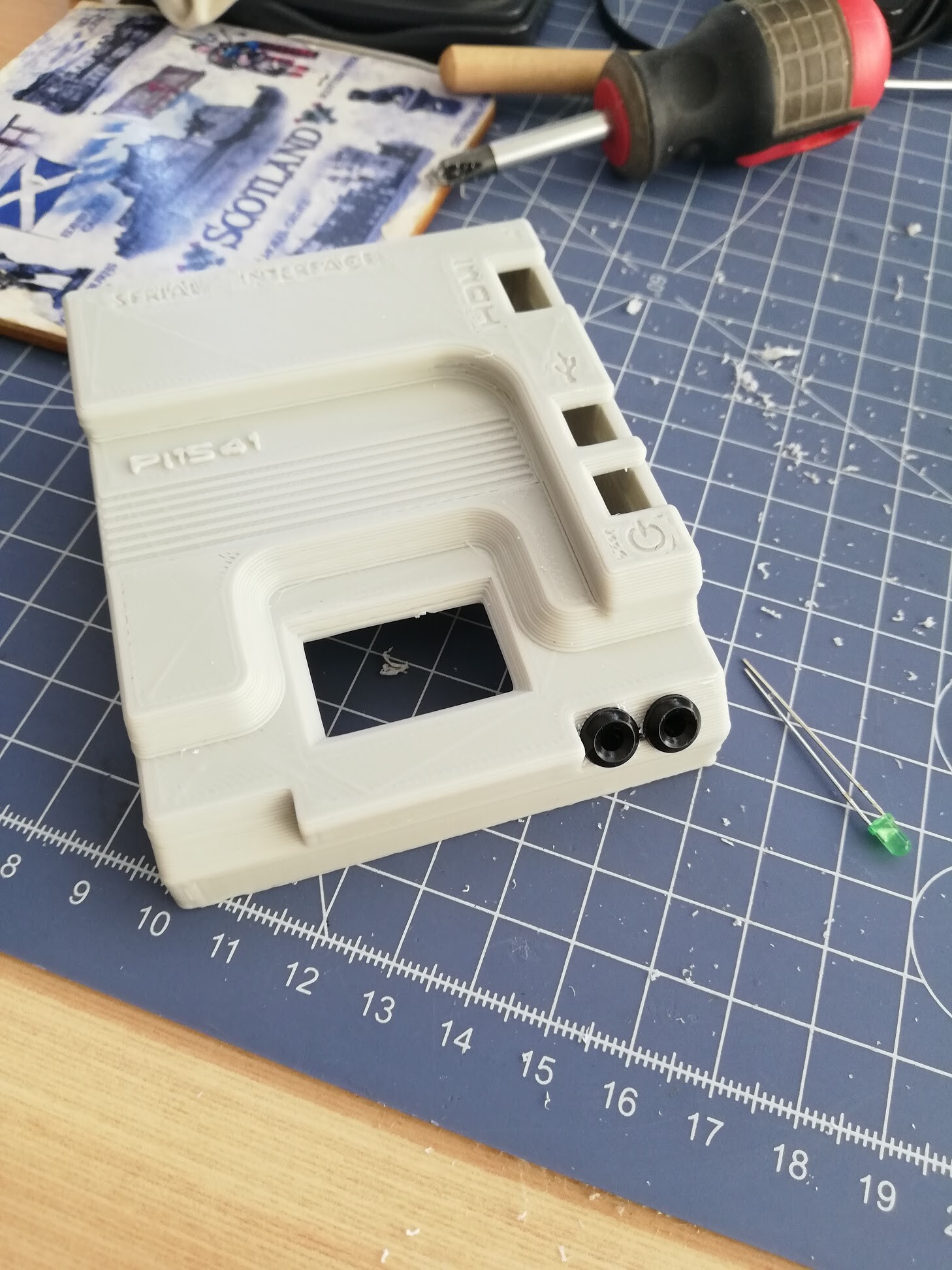
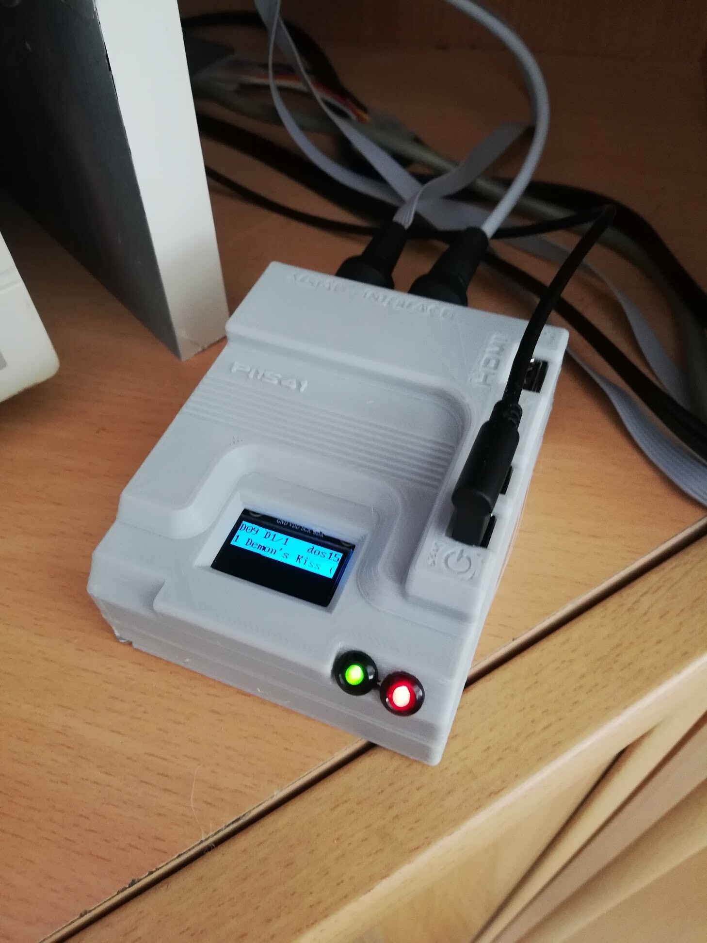
I soldered the LED extension cables.
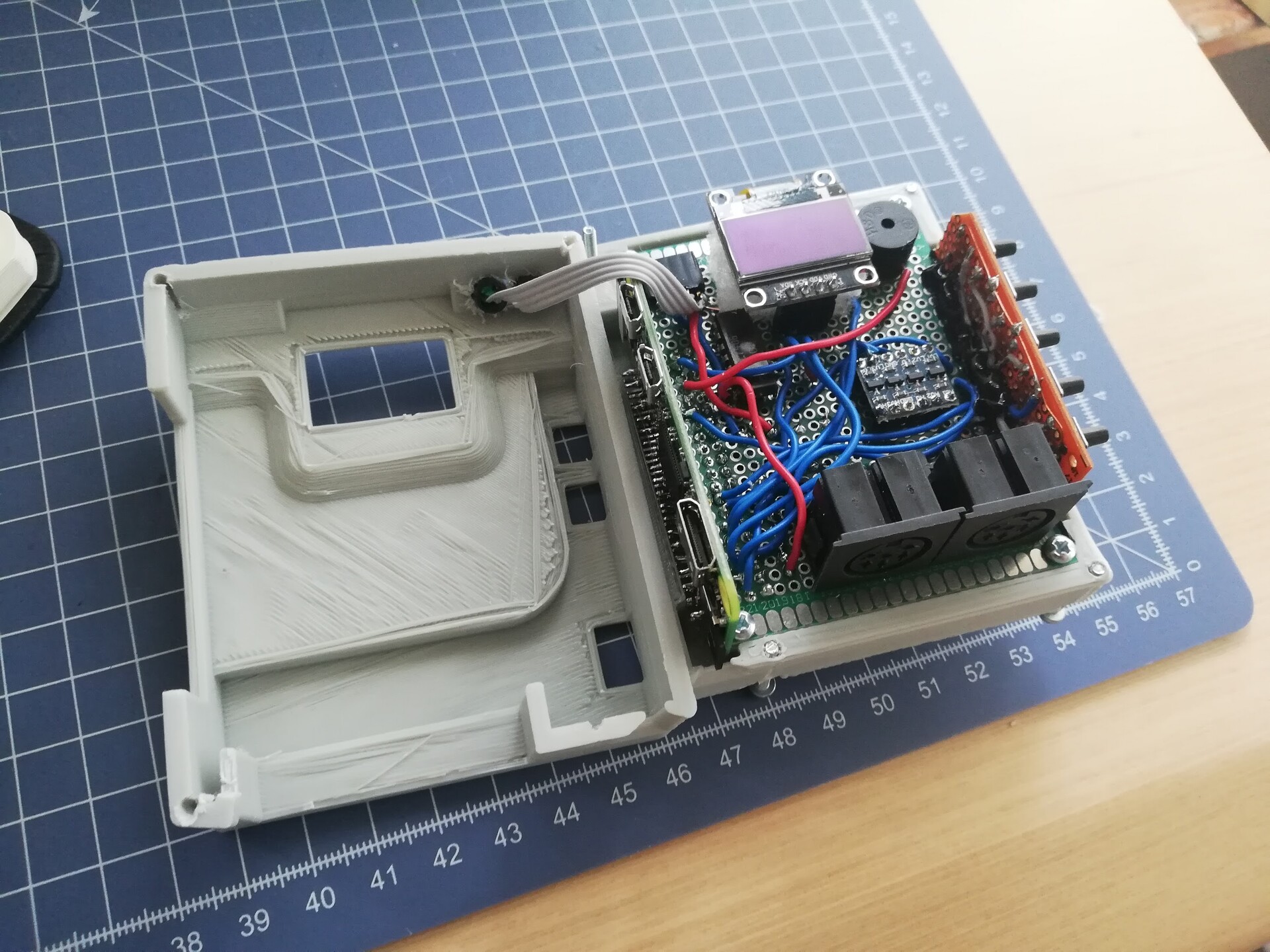
And it's complete.
Working good as a disk driver on real C64.

See you on next project! Cheers!