Keycon Revision - Gamepad Controller with Keyboard Layout

Making Of / 24 February 2025

Hi! Previously I made a game controller with a keyboard style. You can check this blogpost of the previous progress. 

https://www.artstation.com/blogs/blockmind/KGV8m/keycon-making-a-gamepad-controller-with-keyboard-layout

This time I revised and refurbished the design a little bit more. Here is the last look of the Keycon before this update:

First of all, I changed the assembly system to mount the case with screws to make it fully accessible for maintenance.


I nearly reached to the boundary of the build plate of my 3d printer which is Creality Ender 3 - V2.


 And then, I added a led switch to turn the LEDs on and off.

After seing that the screw mounting works, I changed the front design to make it look more like a gaming keyboard.

And 3d printed it as well:

I covered the surface with two sided tapes to fix the cover art I made in Substance Designer.

I have used PBR render node to pre-render my Electronics / PCB Substance Material, to get a 3d shaded visual to put behind the glass design on the design.

I put the images into Rhinoceros to scale and crop the design as the exact shape of the top surface outline I have extracted from my CAD model.

I printed and laminated the print and then I fixed it over the top surface of the new case. 

Before that I bought brown rubber keycaps to make a better looking final look on the design. These keycaps with rubber grips are amazing for playing fighting games with keyboard!  Here is an amazon link for them:
https://www.amazon.com/Ranked-Rubber-Translucent-Mechanical-Keyboard/dp/B09WPM4MD3?th=1

I put the cover design, keycaps and also the "hole caps" There were 4 holes for letting the screw driver in for fixing the controller circuit to the case. I closed those holes with rivet looking caps.


By the way, I tried to made a 90 degrees USB cable. I soldered it first and drew a rough outline:

I 3d printed it and used UV resin to seal the whole guts inside and glued thejhatch of it.


I made another controller too!


So that's it, I really liked the result and happy that the controller is really useful on playing especially fighting games. I hope you like it, and see you on the next creation :)

(Keycon) Making a Gamepad Controller with Keyboard Layout

Making Of / 30 January 2025

Hello! Lately I was playing so much Street Fighter 6 in online ranked matches. I had got into this game to see as a 42 years old -old school gamer, would I be compete with younger opponents since the last Street Fighter game I had played was the Street Fighter II in 90s :) 

After a while I managed to get #1 ranked Ryu in my country (Turkey) which was amazing achievement for me!

I was playing this game with keyboard btw. Here is a footage that I've recorded that show how I played with keyboard.


As a SF6 player that uses keyboard as controller, I'm not planning to be a tournament player (which requires much talent and effort than I can have) but since Keyboard is not allowed on Tournaments when the game runs on PS5, I thought that it might be a good idea to physically create my keyboard layout on a gamepad USB interface electronically.

Here is a section from the rules on Capcom's page

5. Keyboard usage:
Keyboards are allowed only if the platform used in the tournament is Steam. However, keyboards must adhere to these rules in the same manner as controllers.The keyboard alone is not allowed to compete in offline CPT tournaments and must be paired with a controller. 

https://sf.esports.capcom.com/cpt/rules/

I recently bought some buttons for my Arcade Cabinets. And they come with a USB interface that you can connect gamepad buttons on the circuit and connect that thing to a device with USB. Here is a link of one of them:

https://www.amazon.com/Hikig-Buttons-joysticks-Controller-Raspberry/dp/B07JFXQSM5

So I started by cutting out some PCB from one of my dead keyboards to solder some mechanical keyboard switches on it.

And next I desoldered anything that I don't need on the PCB. Like integrated circuits, resistors and other components.

Also I have removed the connectors of the USB gamepad interface board to get more space for my case design.

I cutout the keyboard PCBs such a horrable way, so it was nearly impossibe to place them to a case design. So I "scanned" them to get a true scale outline of the boards.

I placed the scanned documents into Rhinoceros, and created the outline for them.

Then I moved the outlines into Plasticity and made a 3D design by taking several measurements of the PCBs. 

I made the arrangement to fullfill a necessary width for the buttons, to keep my hands not so close to each other. Because if the left side buttons and the right directional buttons got too close, it would be hard to use that console ergonomically. But if I set the width too wide, then I would need to 3d print the case in multiple parts since it would exceed the build plate boundary which has 240mm by 240mm.

After the 3d printing is completed, I placed the PBCs and started soldering the pinout of the buttons. 


Keyboards has a matrix style connections, so I cut the traces of each button trace to prevent any short-circuit.

And the case is completed with all electronics inside.

While I was testing and playing with the controller, there was no problems so far, so I've sealied (glued) the case altogether which means there is no possibility of maintenance after that point. But after using it a few minutes more a strange thing happened because down button and C button got short-circuited.

That was a terrible thing since I couldn't reopen the case without breaking it, so I cut a whole at the bottom side to hopefully see what is wrong inside. But let alone finding the problenm, when I cut the window at the bottom, I terribly scarred the PCB and cutout the traces of the controller circuit. As you can see on this photo that scratch cutout 2 bottons to function (Z and X).

So with a coated wire, I tried my best to fix the traces.

I tested the system and somehow the first problem was gone and the 2 missing buttons came back to life. So I used UV resin to seal the amateur repair that I made there.

After closing the back side with some folio, I go for printing a good artwork for the front cover. I used the curves of my 3d design and placed one of my artworks on it. Then I printed and laminated the coverart. 

Then I cut the outline and applied it to the controller with a two sided tape.

Here is the final result. 


I'm attaching two videos from my youtube channel to show how the controller works on both Desktop PC and my Steam Deck. I hope you like it, and always thanks for reading.


Making of a 14.5" CRT "Vertical" Bartop Arcade Machine

Making Of / 02 May 2024

Hi everyone! I came with another bartop arcade cabinet making of. But this time it has a "vertical" screen!

Single screen arcade games are mostly designed for horizontal screens but there are also many games that designed for vertical screens as well. Most of them are shoot em ups but there are also platformers and puzzles too. Most of the iconic vertical games are Pac-man, Donkey Kong, Raiden, 1942, Esp. Ra. De, Frogger, Aero Fighters etc. 

Playing those games on a horizontal screen is also possible with today's emulation technology, but if you're playing on a CRT screen, emulation screen is resized from 240p to 576p which means 2x more scanlines, you get black bands on both sides and also you lost details of pixelart because of the shadowmask of the screen. Detail loss is also caused by the direction of the scanlines. Because the scanlines supposed to be vertically since the graphics are designed by the aspect.

The following image shows the detail loss of a rotated image represented on the same screen.      

I'm not a super fan of vertical games but I really wanted to make a cabinet to play those games as they are supposed to be played.

I bought a 2nd hand 14.5" CRT screen which is the same model with my previous bartop project.
https://www.artstation.com/blogs/blockmind/EgoA/making-of-a-crt-tabletop-bartop-arcade-machine-part-12
https://www.artstation.com/blogs/blockmind/Y1gw/making-of-a-crt-tabletop-bartop-arcade-machine-part-22

The tv is a Premier brand 14.5" CRT TV. since it's not a generic design, I took measurements of the TV to create the design. 

Since it's a all design, I put the all the models I've created so far together to realize the form factor better.

I created a cut list and ordered some laser cutting service around.

Meanwhile, I made a roadmap for the interior electronic assembly. I was going to use RGB-Pi Jamma product (https://www.rgb-pi.com/), which is the best arcade solution for extraordinary refresh rate suport for any arcade game. Also it supports screen rotation for vertical screens.

This was main electronic assembly idea I've planned for following. I also put some pinout references to solder the cables correctly.


 The first important thing about this cabinet was the "jamma to scart" cable conversion. I started labeling the cables and soldering them to their corresponing pins.


I've tested the video output and itworks great!


Now it's time for the button cables. I've used classical concave arcade buttons with mechanical switches.

And all the pins are soldered to the Jamma Connector.

I've used terminal sockets to easily swap the switches.

This is the interior cables so far. There is a DC-DC stepdown module that reduces 12 volts to 5.25 volts which is needed to operate the Raspberry Pi4 that I'm going to use. I used a temporary board to fix the buttons and the joystick and tested them.

Finally I've received the cut panels that I've ordered and whole system was ready to assemble!

I fixed the laths to the panels for all of the 90 degree connections with the screws.  

Pretty primal approach as I drill a hole for the fixing point and tighten a  screw through there.

I finally placed anbd fixed the screen to the screen frame.

I fixed the TV motherboard as well.

This is how it looks so far.

I designed a marquee. Actually I'm continuing the legacy of the title of the cabinet that I bought some years ago which is named as "Delta II". I think they were popular in early 90s. This is called Delta V this time where the V is stands for the "vertical" as obvious :) 

Since the width is 32cm, it wouldn't be possible to print it to a A4 with my printer. So I printed two parts of it and aligned them and cut them together. After that I taped them together. This approach reduces the seam between the prints. 

I made the controller part design with Substance Designer which is always a fun.

I applied the same approach since I can't print out this as one part too.

I started applying sticker folio. I think these are used on cars. I ordered a blue rough folio with some carbon fiber texture on it. It's not perfect but since I've used the same on on the previous designs, I didn't hesitate to continue using it.

I added a vertical board to the top to hold the electronic content.

Cabinet is looking nice alreay. But the screen frame needs to be covered too. And there is a gab between the screen frame and the controller board which I will try to solve on later stages.

I added laths for the screen glass (which is also a plexiglass panel) and covered that laths with black folio as well.

Next,I used corner protector rubbers on the edge of the screen glass. These are sold for covering furnitures with sharp corners to prevent any harm to the little kids that newly walking.

Looks really nice with the balck frame around the screen!

I fixed the power switch and the 12v power supply to the back panel. So I distribute 220v AC to both TV and the PSU.

I fixed a led strip back to the marquee and connected it to the 12v output of the PSU. It was strange that 3 of the LEDs were not working so I cut a 3 LED piece and re-soldered it.


Next, I fixed the jamma connector so the cables and the solders on them won't get damage on movement.

This is how the top compartment looks.

Previously I mentioned about the gap between the controller board and the screen frame. I sed PVC for closeing the gap there.

Worked perfectly!

I 3d printed some stands fur rubber feet. So the cabinet stands better and sticks to the ground.

And finally added stickers for the front buttons and called it finished :)

QC passed by my son Atlas!

Some final shots of the cabinet:

And of course some gameplay. I hope you like the process, and as always thanks for reading!


Two Years of Environment Design for an Unreleased Tactical Shooter Game - Part 3

General / 19 February 2024

1st Part: https://www.artstation.com/blogs/blockmind/oAAP6/two-years-of-environment-design-i-made-for-an-unreleased-tactical-shooter-game

2nd Part: https://www.artstation.com/blogs/blockmind/n77W9/two-years-of-environment-design-i-made-for-an-unreleased-tactical-shooter-game-part-2

I've been contracted as an environment designer for 2 years by a game company for a tactical shooter game which is unfortunately cancelled before it's released. Here I'm dropping some of the parts I made for the game and putting some in-game footage of the pre-alpha version.

We worked on Unreal Engine 4, and I used Modo, Substance Painter, Substance Designer and Zbrush. 

5. Constuction Yard


Two Years of Environment Design for an Unreleased Tactical Shooter Game - Part 2

General / 18 February 2024

1st Part: https://www.artstation.com/blogs/blockmind/oAAP6/two-years-of-environment-design-i-made-for-an-unreleased-tactical-shooter-game

I've been contracted as an environment designer for 2 years by a game company for a tactical shooter game which is unfortunately cancelled before it's released. Here I'm dropping some of the parts I made for the game and putting some in-game footage of the pre-alpha version.

We worked on Unreal Engine 4, and I used Modo, Substance Painter, Substance Designer and Zbrush. 

3. Props that I've made by High poly to Low poly baking workflow on a 2k single Atlas.


4. Additional Various Places


Making of a 10" CRT Bartop Arcade Machine

Making Of / 17 February 2024


Hi everyone. A while ago I bought a second hand 10 inch CRT TV from a seller. Considering the size of it, it was looking great to make a CRT arcade cabinet with that one. 

  1. My Previous Cabinet Projects

Previously I made a cabinet with an 8" LCD screen. That was a portable, small, 1 player good cabinet. Only downside of that one was it has LCD screen, not a CRT. 

https://www.artstation.com/blogs/blockmind/PvdE/making-of-a-tabletop-arcade-machine

Next I acquired a 13" CRT TV and made a cabinet with that screen for 2 players.

https://www.artstation.com/blogs/blockmind/EgoA/making-of-a-crt-tabletop-bartop-arcade-machine-part-1-2
https://www.artstation.com/blogs/blockmind/Y1gw/making-of-a-crt-tabletop-bartop-arcade-machine-part-22

The new one is the middle one on this render:

2. 10" TV and the Idea

The TV a got is a 10" Schaub Lorenz with a SCART input. I heard the name for the first time.

The most important feature of this TV is that it is a multy-sync TV that supports refresh rates  from 50 hz to 60 hz. This is important since many arcade games have variated screen refresh rates like 54hz, 57hz etc.

Since it has a small size, the phospor pattern is so visible but as a good news, scanlines are less recognizable. 

3. Making of the Case

Before getting into wood panels (actually I use MDF panels) I disassemblied the TV and quickly measured the outer dimensions of the CRT tube. This way I made a quick design with Solidworks to fetch a cut list.

And I exported the DWG files for the panels and ordered a laser cut service from a local advertisement company.

Once I received the cut panels, I realized that TV mainboard can't fit under the tube, so I placed the motherboard to the top on my 3d design (which was a unnecessary doubt since I see that it can fit, later).  

4. Constructing the Cabinet with Panels

I bought some screws and laths to connect the boards. Laths are the best mounting aid for the MDF panels. I measured and cut the laths and placed them on the side panel first.

I used my hand drilling machine to drill holes and tighten the screws.

So after fixing the fisrt set of laths, I placed the panels and hoped that I didn't made a mistake on my quick design :)

Since I needed to fix the laths on the both side panels, I needed to fix them on the exact opposite position. Quadrant is a useful too for matching the angles on both sides. I drew lines for the positions of the laths.

After fixing all the laths, I drilled and screwed the panels one by one.

Since I couldn't be able to draw the hole for the tube hole, I needed to cut it by hand using a jigsaw. I made a terrible job but I was confident that I can cover the problematic gaps with sticker vinyl.

Finally I managed to fix the tube to the frame.

Next, I made a platform for to place the raspberry pi and jamma connector.

5. Electronic Touches and Finalization

Since I'm using a TV, I need to user the remote control of the TV to adjust image etc. It's needed to place the IR sensor of the remote control, because the mainboard of the TV will be placed at the bottom back side of the cabinet. So I desoldered the sensor and soldered a cable to place the sensor at the top of the cabinet.

After moving the sensor, I soldered cables for the connector part. I used a 40 pin connector to detach the controller panel anyhtime in future for maintenance purposes.


I used a DC voltage stepdown module for reducing 12V DC voltage to 5 volts. This way I can use both 12V and 5V DC for jamma to operate raspberry pi and the speaker amp circuit.

I use RGB-Pi Jamma circuit (https://www.rgb-pi.com/) for emulating games. RGB-Pi is the perfect device with its own software which allows me to play the games at their original refresh rates. It works great with multisync CRT screen so this way TV shows the smooth scroll gaming on specific refresh rates. Classic arcade emulators run at fixed 60hz / 60fps. This way games that designed less than 60hz runs faster than their original way or you get screen tearing, frame skipping or other issues on emulation.

I placed the power switch to the left side of the cabinet by cutting a hole for it. I connected the 220 AC input the that switch and distributed that voltage to a 12v DC adapter and the TV itself.

Works fine! So I closed the back panels and moved on with the covering the panels with vinyl folio.

I got some spare sticker folio from the last project so I applied it to the side and front panels.

I used the previous design that I made for the LCD cabinet and put a CRT label to the top. Printed and applied to the plexiglass I have for the marquee area.

For the controller area, I used Substance Designer to make a procedural panel design and applied a shading for it with PBR render node within the software.


I fixed the plexiglass to the marquee window with hot glue. And then I used double sided tape to fix the printed out paper over it.

I cut the holes with the knife on the controller print-out. I cut the same holes over the PVC plate so the paper won't be affected by the hand sweat or dirt in time of usage.

This is how it looks so far.

There is a screen glass I ordered for cutting and it will be placed over the actual screen. But before fixing it over the CRT screen, I needed to cover the area around the screen with black sticker vinyl.

Since I badly cut the frame around the screen, I applied some pvc sheet over the gaps between the screen and the frame by double sided tape.


After that, I covered a lath with the same black vinyl and fixed it to the plexiglass with screws. And then I drilled and screwed the laths that attached with the plexiglass to the cabinet side boards.

I had some rubber corner protection stripes that sold for protecting children to get injured by the sharp corners of the home furniture. I fixed that stripes to the screen glass edges.

Looks better!


A quick tesy by my son.


Meanwhile the study room is devastated.


As some final touches, I added an LED strip for the Marquee lighting.

For the sound system, I had a spare speakers that I had by my old broken hometheater system. I used center speaker set of it and fixed the speakers to the back board.

And the cabinet is ready to use. I put all 3 pieces I made so far side by side.

Hope you like the result, and as always, thanks for tuning in.


Two Years of Environment Design for an Unreleased Tactical Shooter Game - Part 1

General / 01 February 2024

I've been contracted as an environment designer for 2 years by a game company for a tactical shooter game which is unfortunately cancelled before it's released. Here I'm dropping some of the parts I made for the game and putting some in-game footage of the pre-alpha version.

We worked on Unreal Engine 4, and I used Modo, Substance Painter, Substance Designer and Zbrush. 

1. Subway Atlas with Substance Designer


2. Various Places


Making of a CRT Tabletop / Bartop Arcade Machine - Part 2/2

Making Of / 24 August 2023

Let's continue from the previous part. you can find the first part by this link:
https://www.artstation.com/blogs/blockmind/EgoA/making-of-a-crt-tabletop-bartop-arcade-machine-part-12


6. Texturing the Cabinet

Before getting into cosmetic details, it was urgent to add another layer over the controller panel, because hand sweat was not good for MDF. I decided to use a translucent plexiglass I had over a while, so I drilled the same holes on it, to use it as an overlay.

Since I was using a translucent plate, I decided to add a personal touch to print and apply it between the MDF and the Plexiglass. I exported this sketch and made a drawing with my good old Samsung Tablet.

I printed out the sketch top two A4 paper and align them. Next I cut the holes and then mounted the controls back.


Now we got a nice shiny look.

Next, I cut a slot hole on the marquee board and mounted another translucent plexiglass behind it.

I printed out another visual. I revised the "Delta" brand and called this Bartop Cabinet as "Delta M" which stands for medium size :) I also added LED lights to lit the marquee part.

I revised the same design with a hand sketch look with my tablet as well.

Now I used spare foils that I had from the previous cabinet and applied to the cabinet starting from side surfaces.

After covering the side surfaces, I moved on by covering the frame of the CRT screen with black foil.


Now it's time for applying the glass in front of the screen. I used another plexiglass for that. I added 2 wooden slats to the sides. Also I drilled holes on plexiglass and fixed it with screws.

Looks shiny!

Now it's time for making everything black inside the outer glass. I started by using black sticker foils on the slats, and then the inside surfaces.

The difference is remarkable!

And I added a rubber edge corner to the screen glass to make a better intersection with plexiglass of the controller glass. 

7. Peripherals Add-On

As a final touch, I decided to add the following:

  • 2 ports USB extension
  • Video Sync port for Guncon Lightguns
  • On/Off Switch for the Marquee Lighting
  • On/Off Switch for the 12V adapter, so it cuts off the jamma connection (This is needed for using composite input, otherwise TV can't process both signals from composite input and the jamma,/scart)

For that purpose I used USB extension cables and a female RCA port and 2 pieces of switches. I also 3d modeled and 3d printed a part to hold these switches and ports. 


Because of a minor design mistake, I used a 3d print finishing tool (it's more like a soldering gun with a flat tip) I melted part to comply with the cables.

Finally I mounted the part to the back board of the cabinet. And used my labeling machine to stamp some labels.

With this add on I can connect Guncon 2 lightguns to play gun games, like this:

You can check this Youtube Short: https://youtube.com/shorts/yp4mpSSyPnc

I'm also attaching some family photos of Delta series. Delta II, Delta S and the new member: Delta M.


8. Conclusion

It was a great experience to build this cabinet. What I love with this cabinet is like these:

  • Screen size and the overal size is really good/compact. 
  • It has CRT, which is the best experience with the "pixels."
  • Smooth scrolling emulation with RGB-Pi in precise on frame rate specific for any game or gaming system is amazing. This makes you perfectionist :)
  • System also can emulate other 8-bit and 16-bit systems like Megadrive, Commodore 64, Snes, Amiga, even Playstation.
  • Jamma port allows me to use origibal arcade boards to use on this cabinet.
  • Composite input allows the system to be used as a simple monitor for attaching any old-school console.
  • 2 or more player can play games together with additional USB ports.
  • Guncon2 Lightguns are supported to play virtua cop etc.

Thanks for reading this, I hope you like the process, and I hope it can be helpful to you on creating your own arcade system. See you soon.

I'm adding some random visuals of the cabinet with different systems and games. Enjoy & cheers!


Making of a CRT Tabletop / Bartop Arcade Machine - Part 1/2

Making Of / 24 August 2023

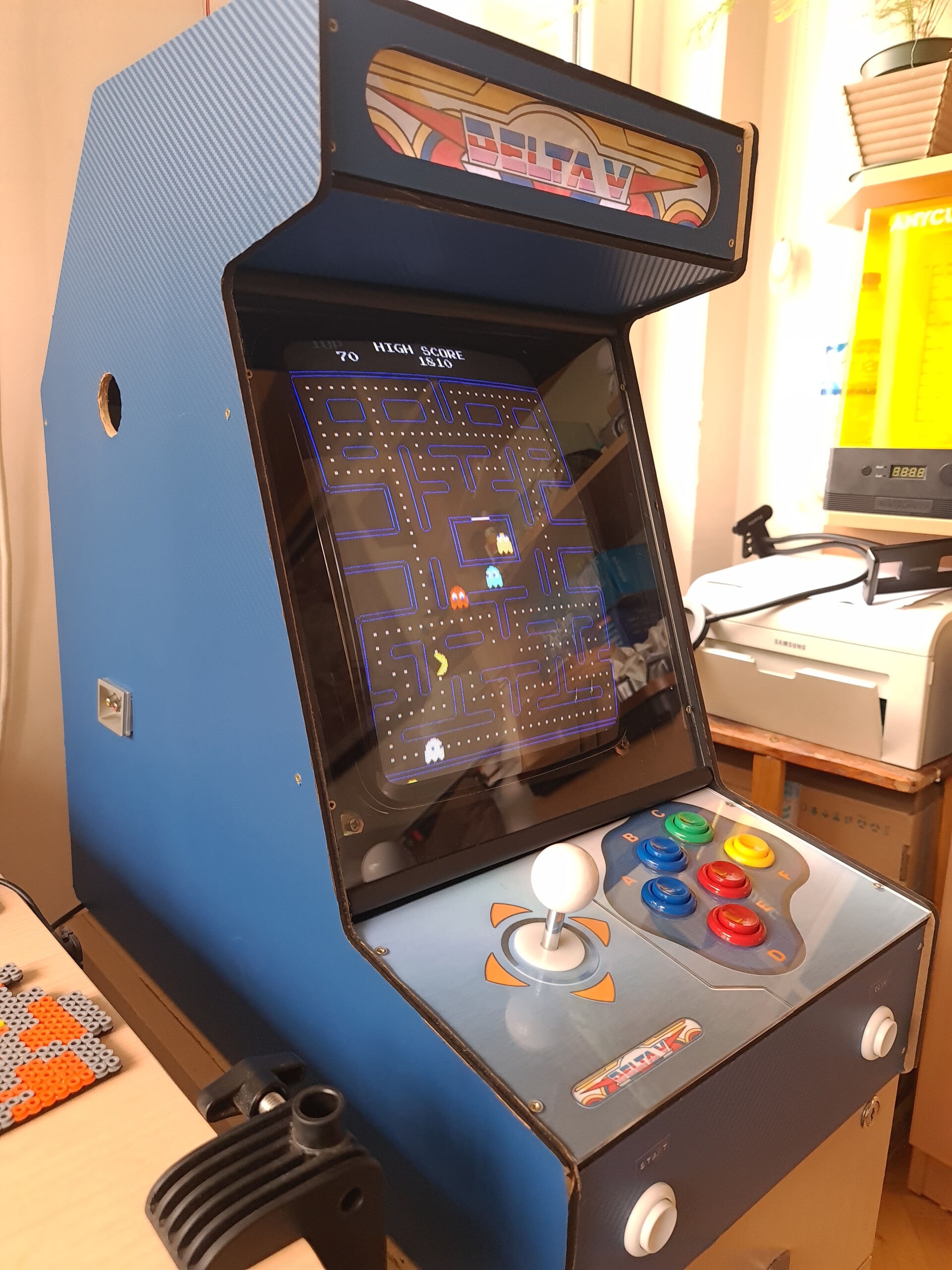
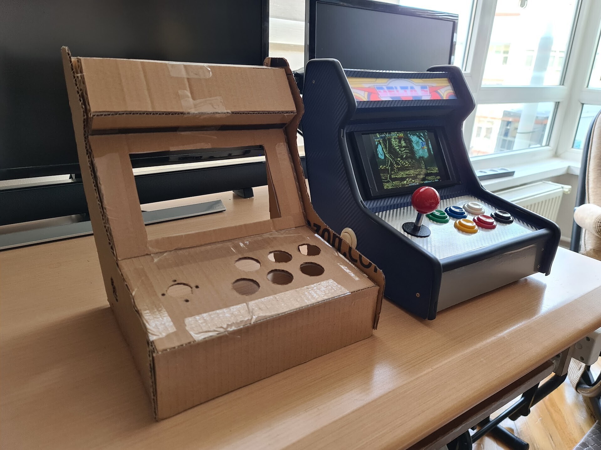
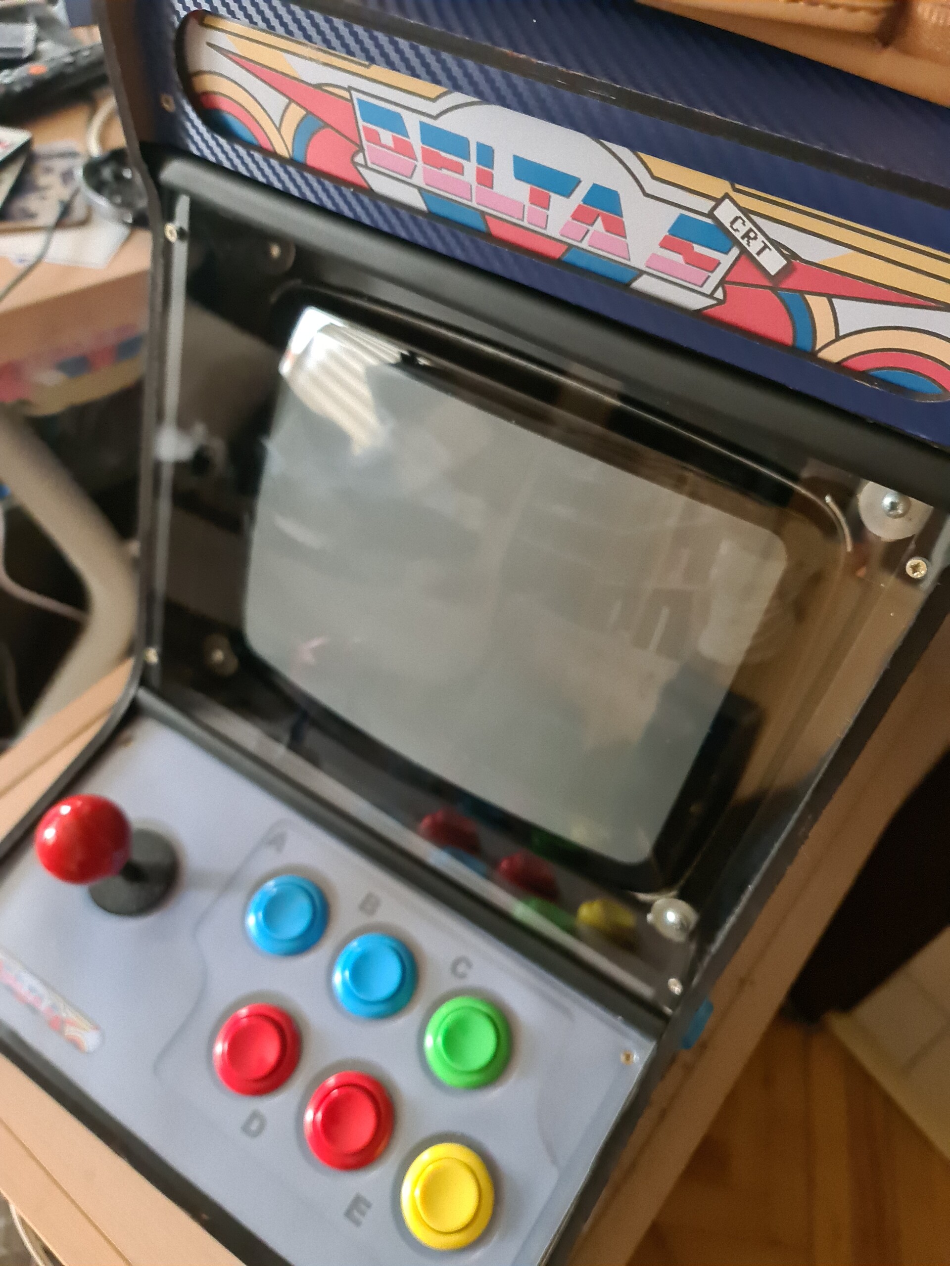
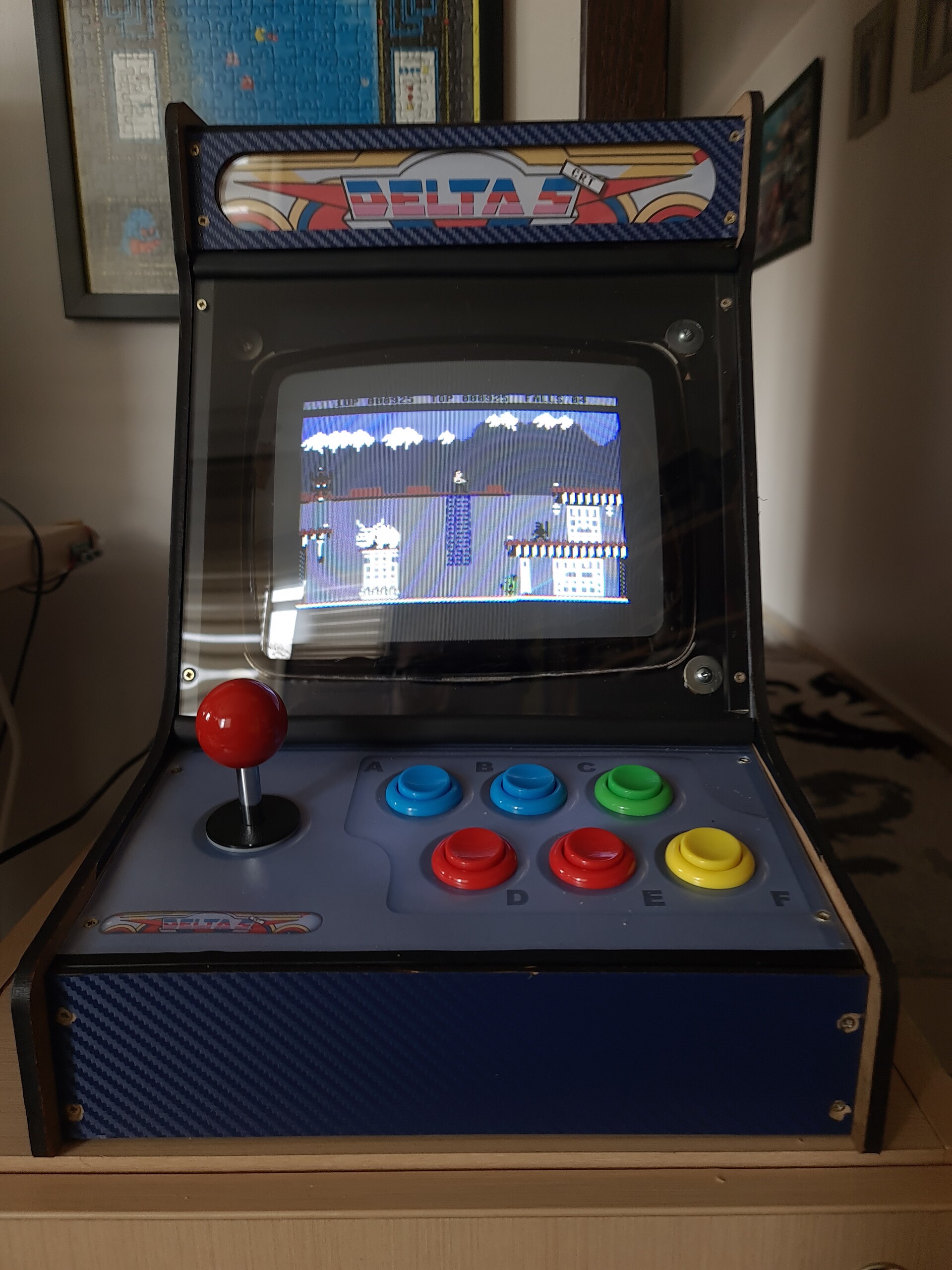
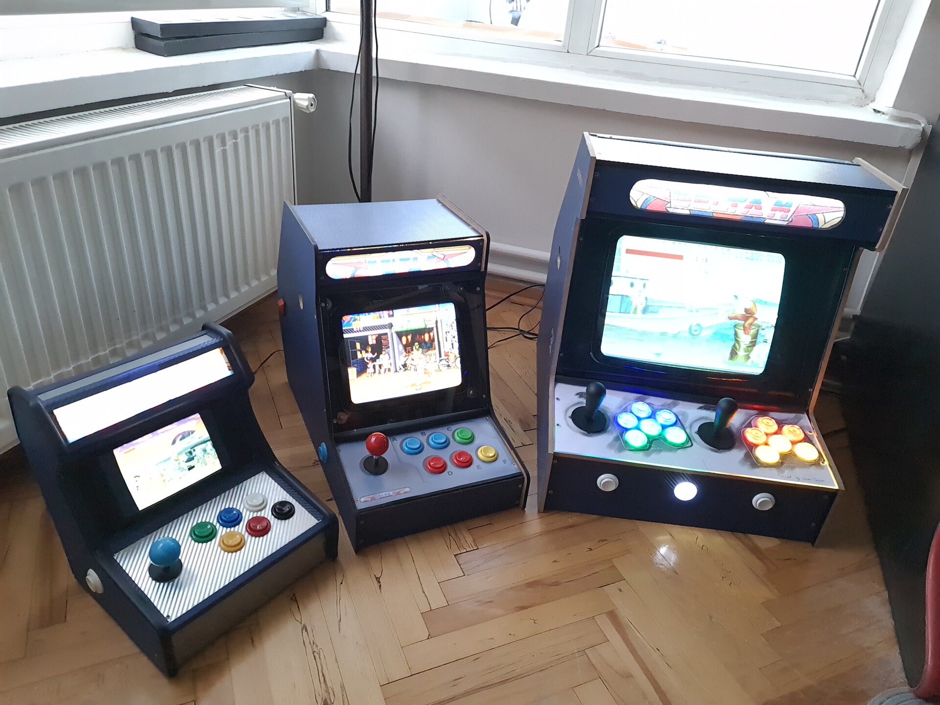
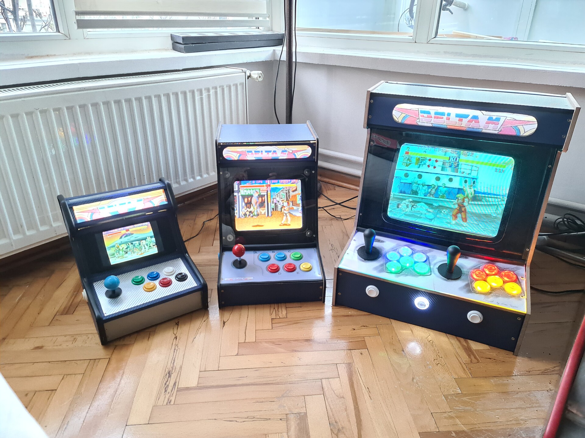
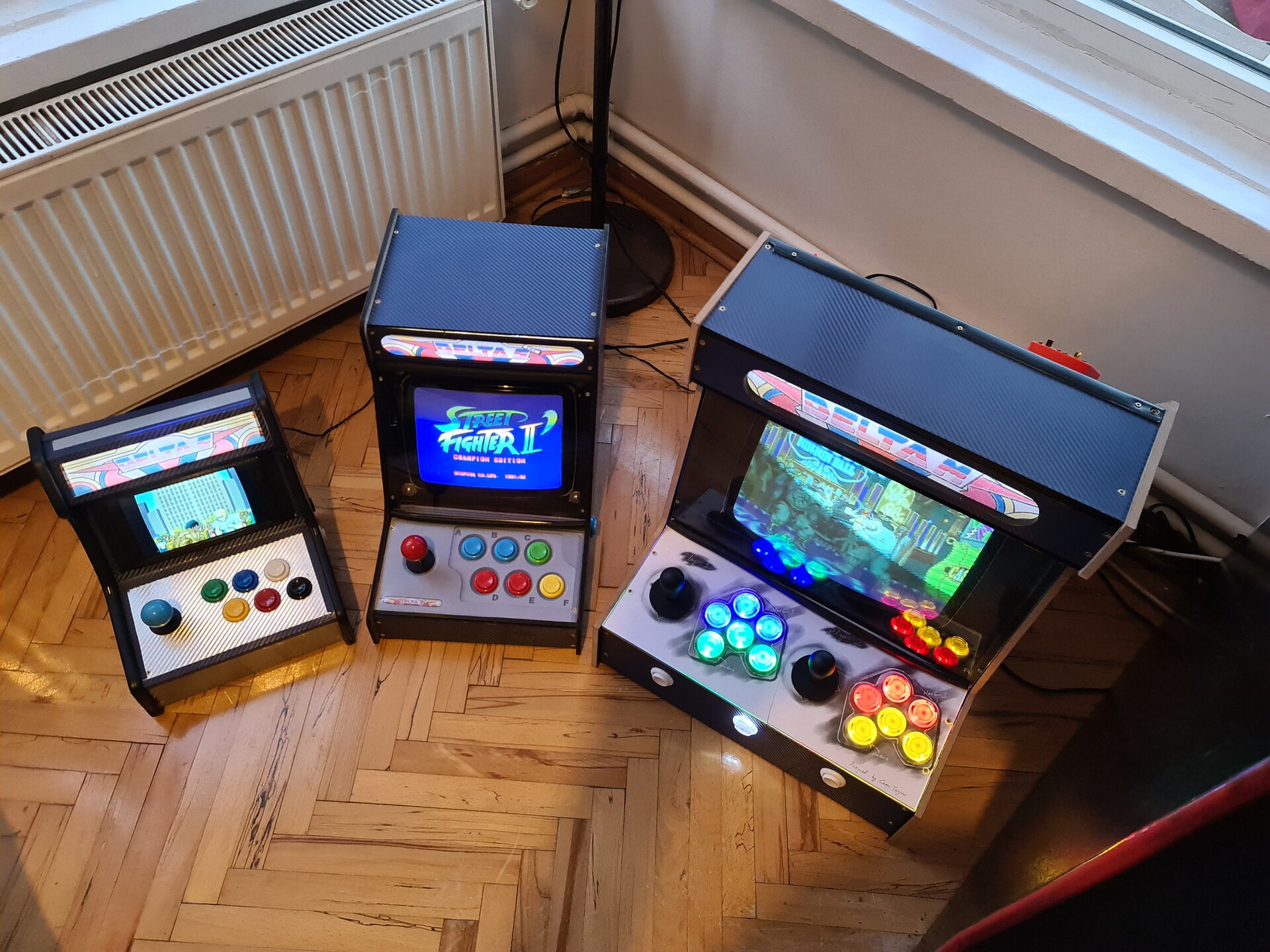
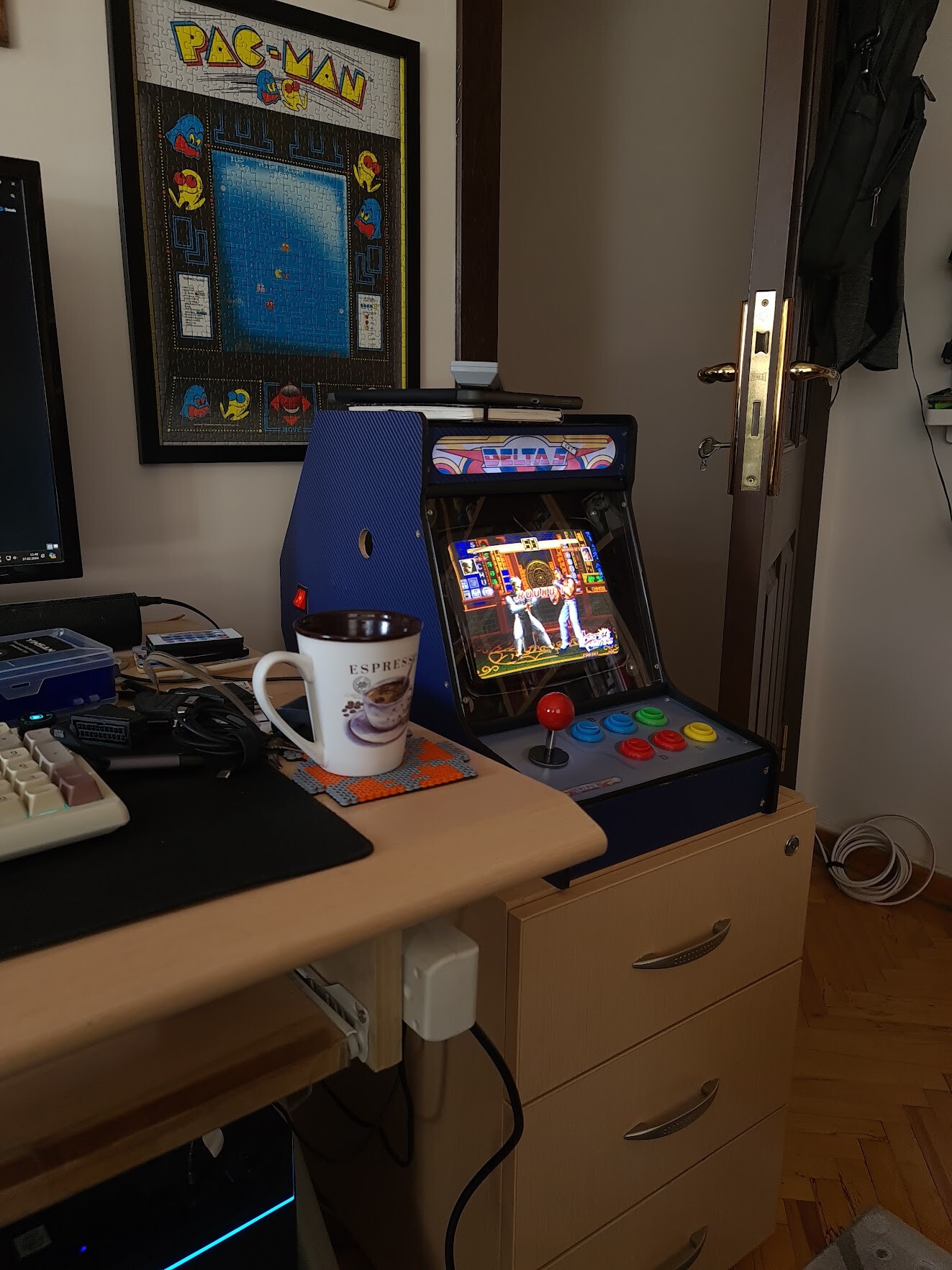
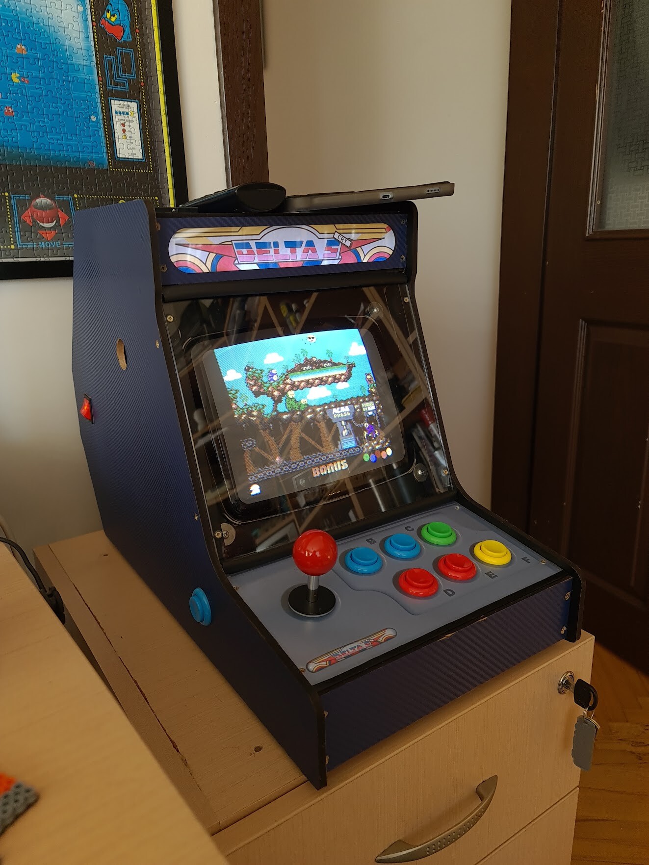
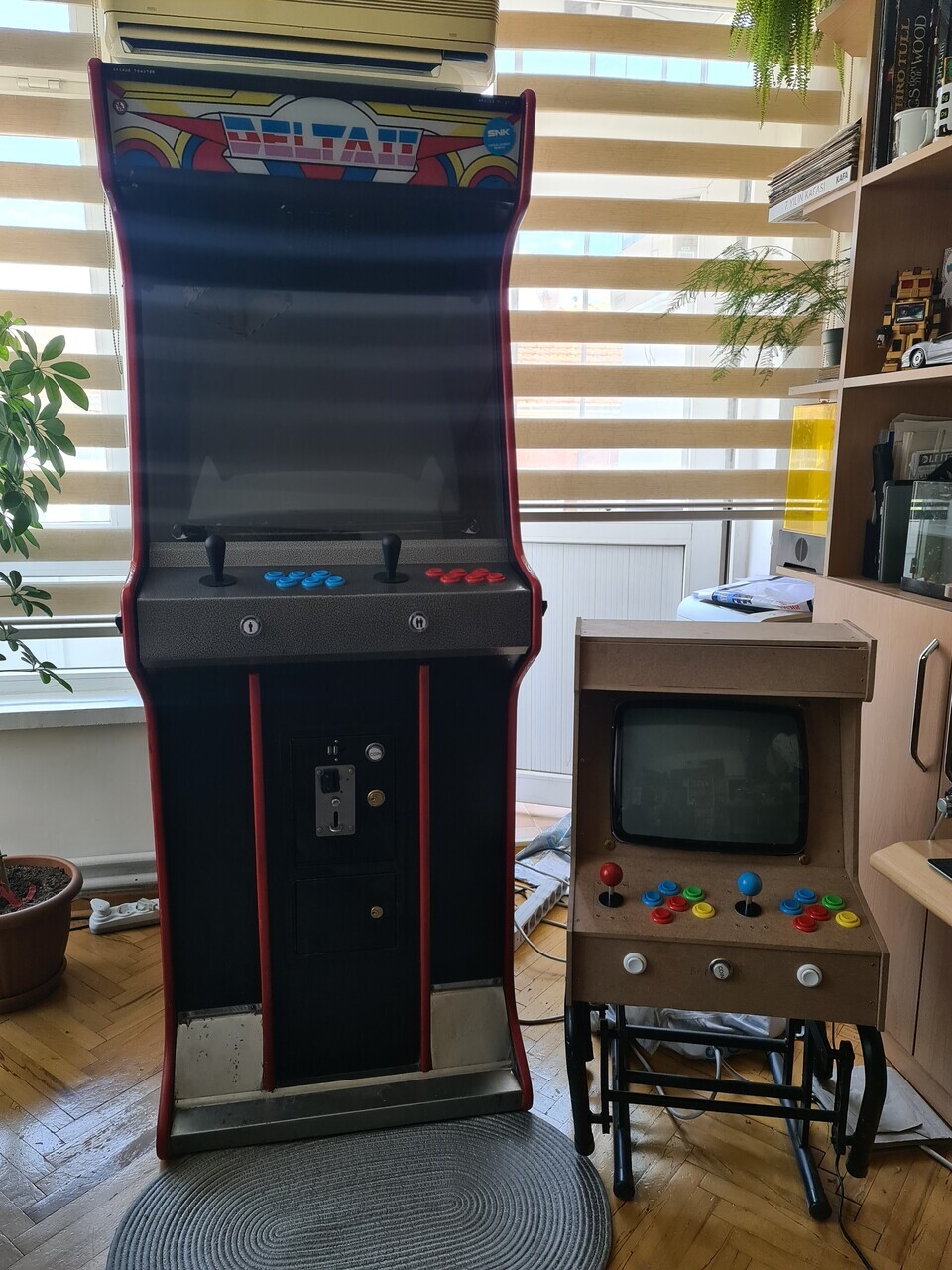
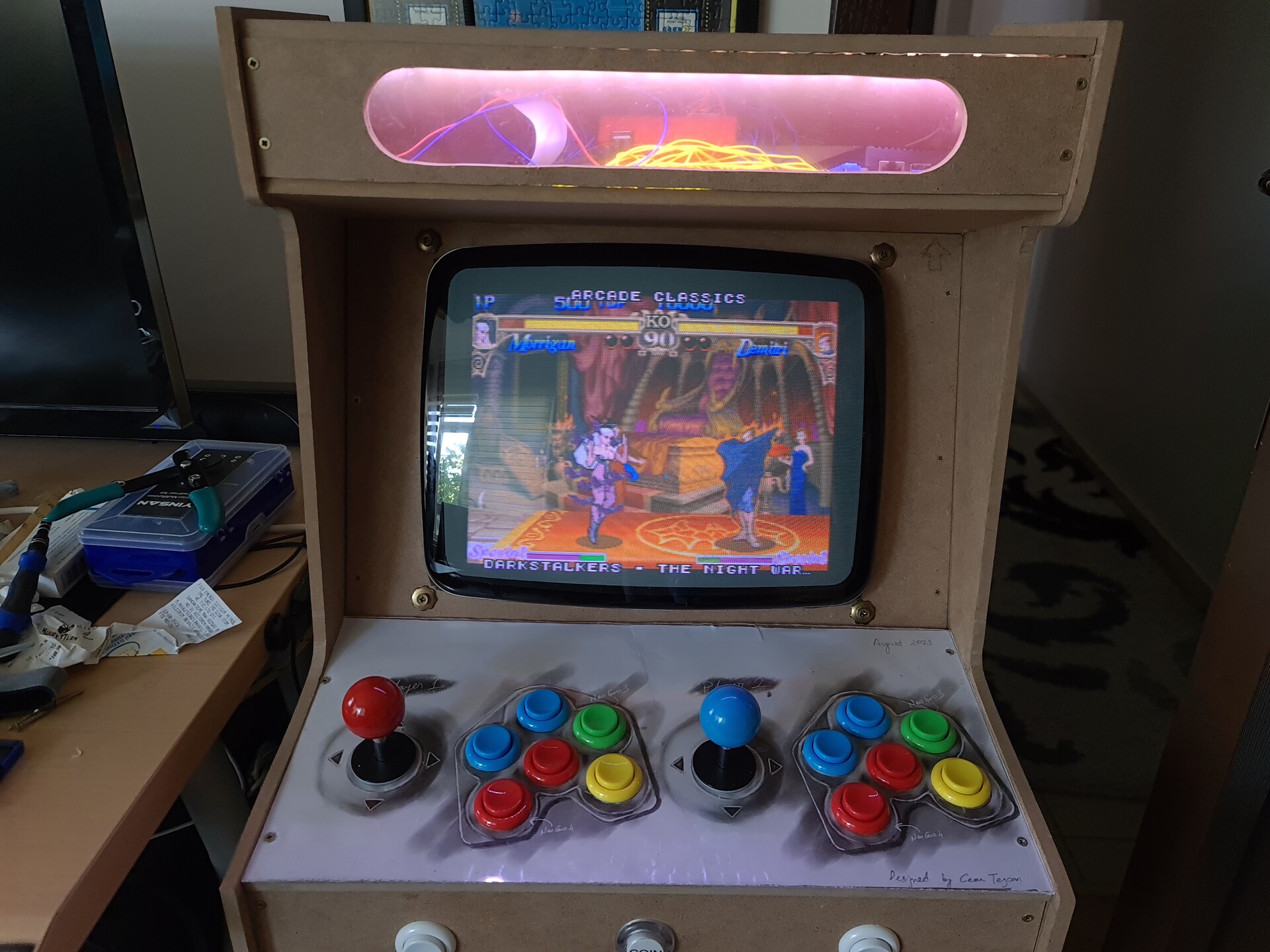
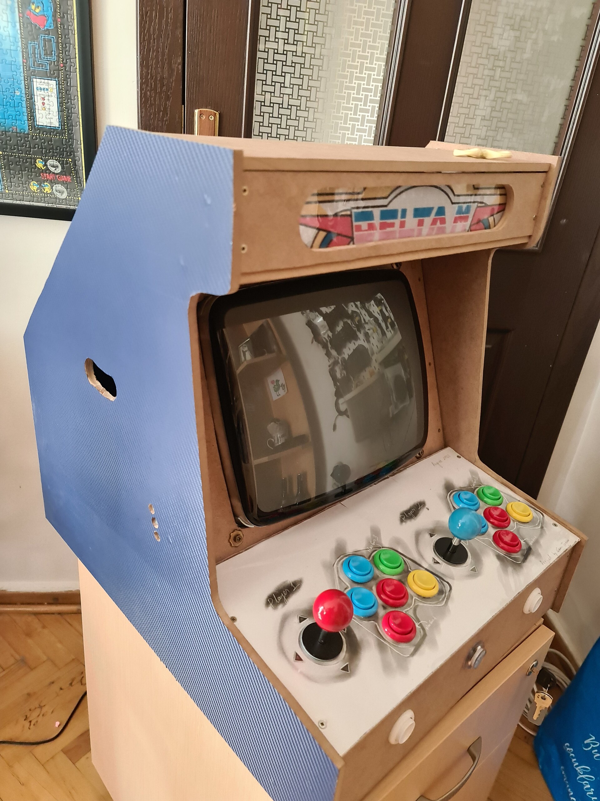
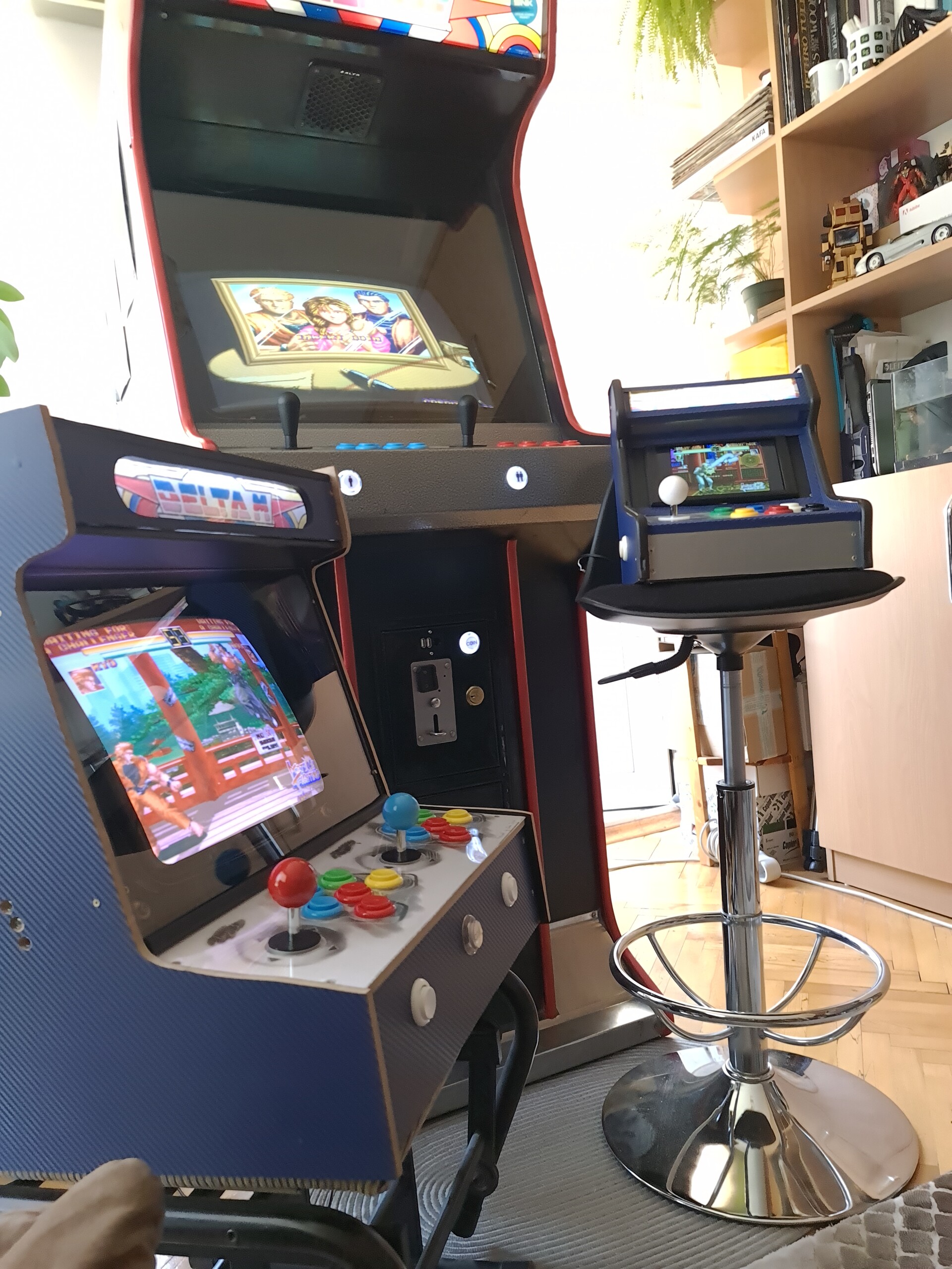
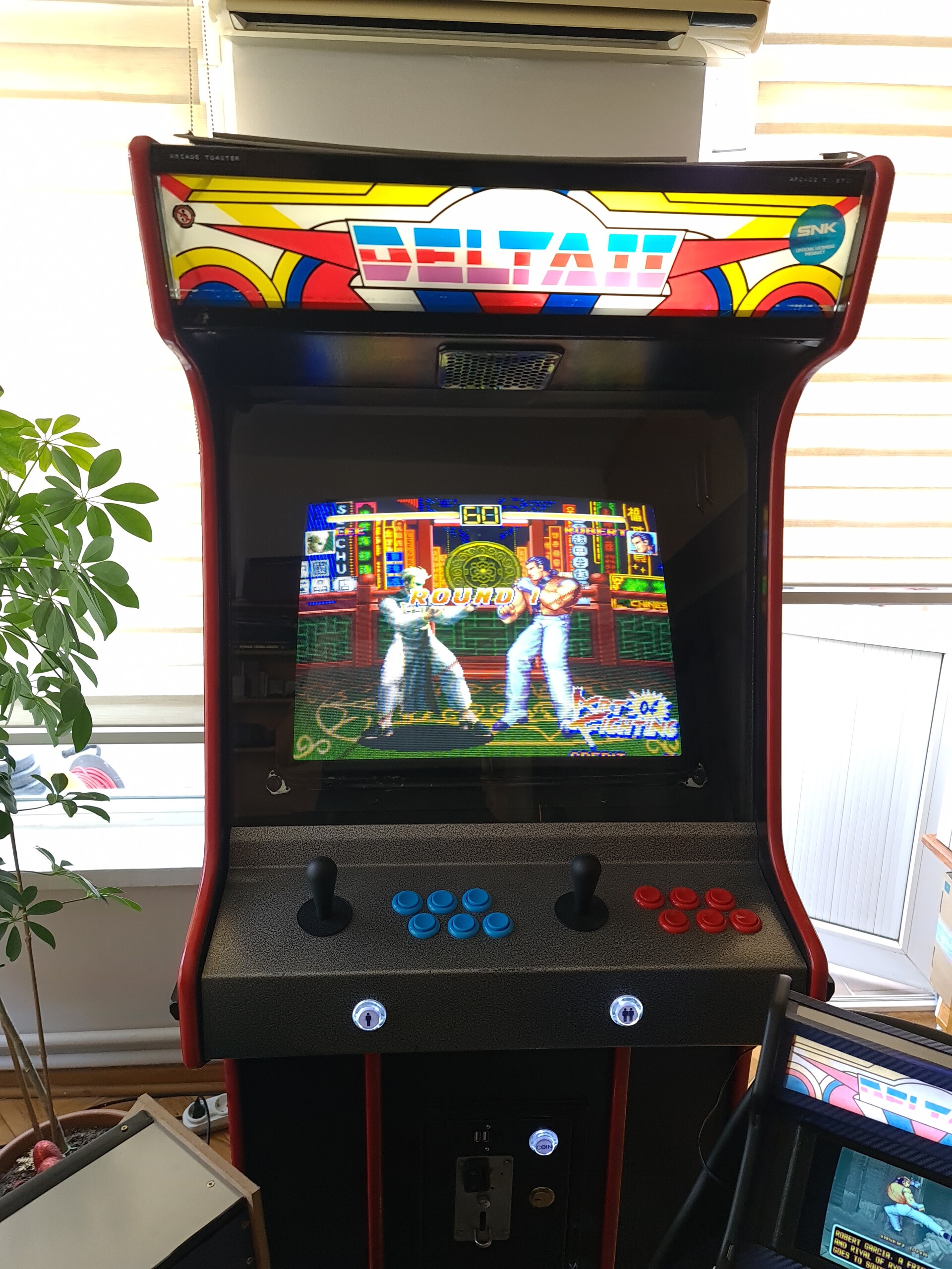
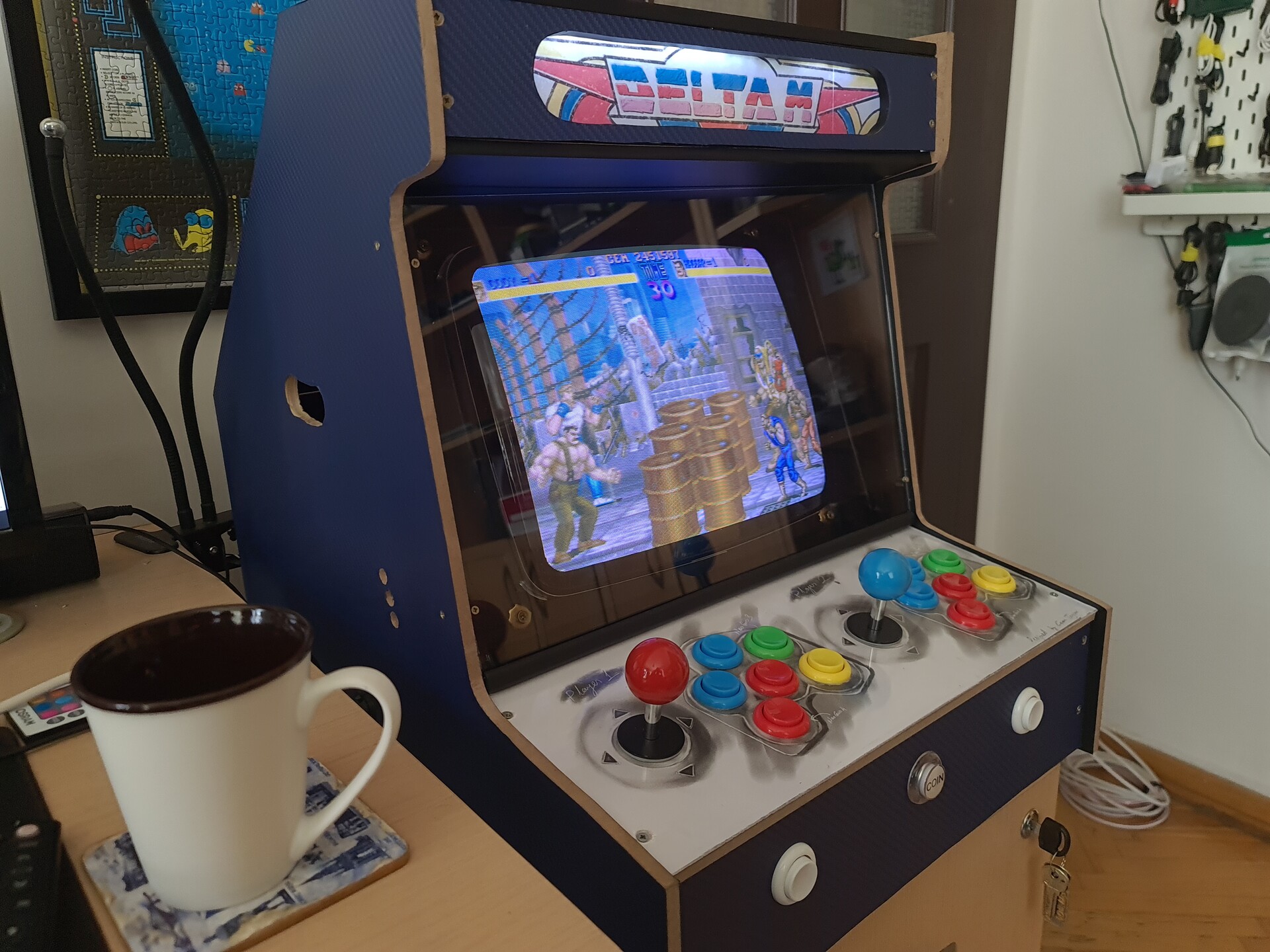
Hello everyone, recently I made another Bartop style arcade cabinet with a CRT screen. This was a real fun project, but the best part is I made it in home by the tools I have. So you can consider it's most part by "DIY".

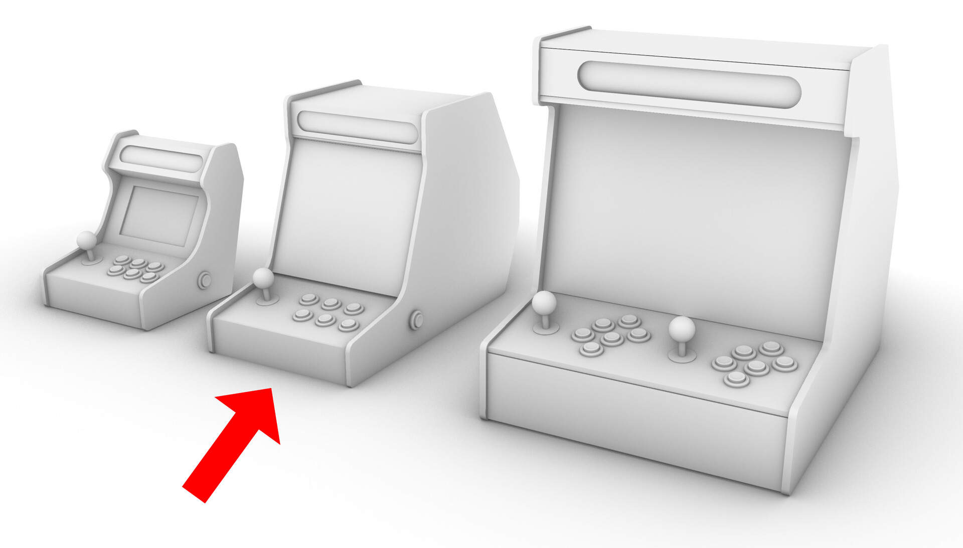
Bartop Arcade Cabinets are roughly more like a trimmed version of upright (classical) cabinets. But they are also designed with smaller screens so the size is smaller as well. You can put them on a table to play. I made an LCD version with one player controller previously. You can check that previous project by this link:

https://www.artstation.com/blogs/blockmind/PvdE/making-of-a-tabletop-arcade-machine 


1. Starting Point of Designing the Cabinet

1.1. The Screen

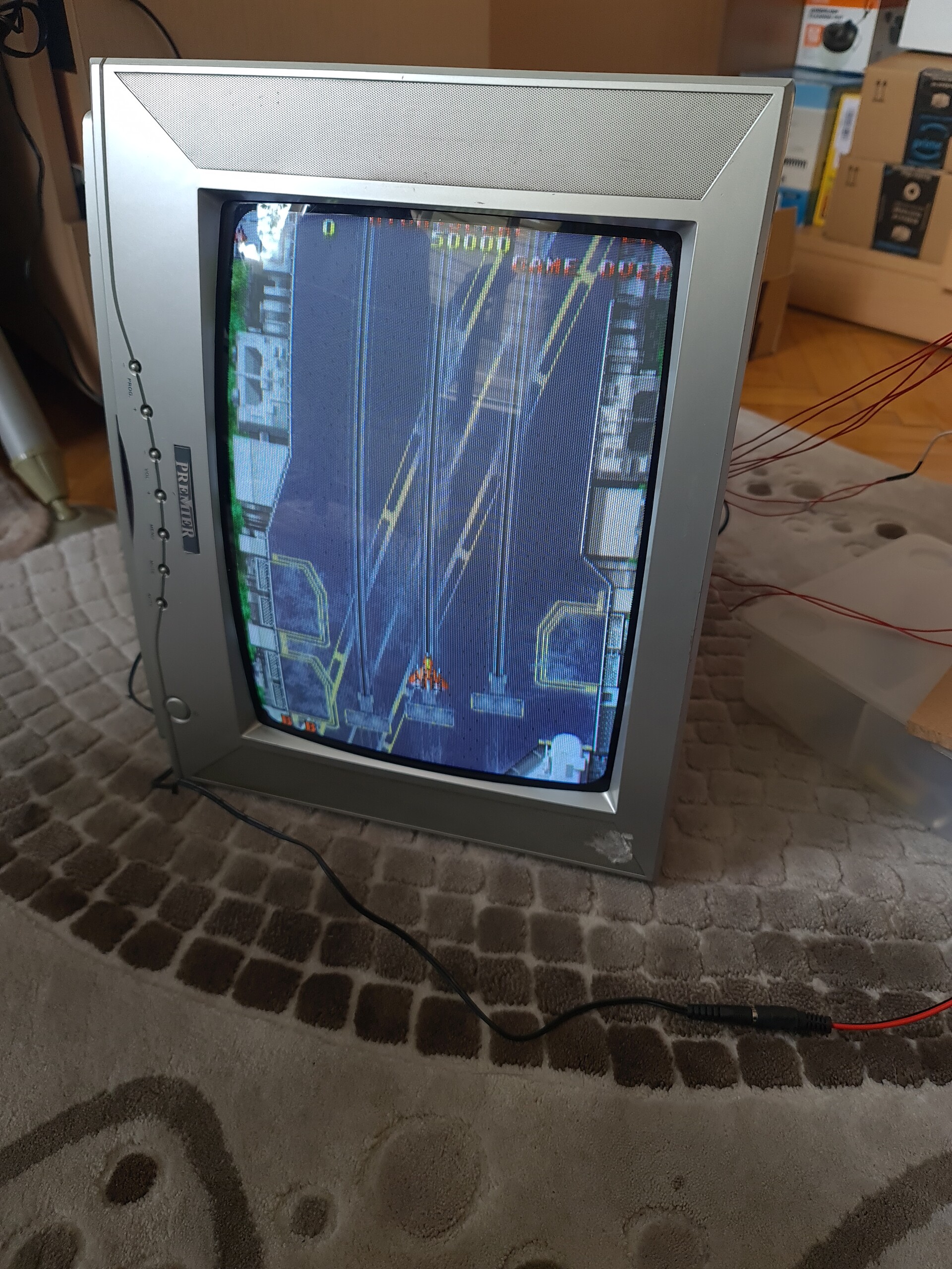
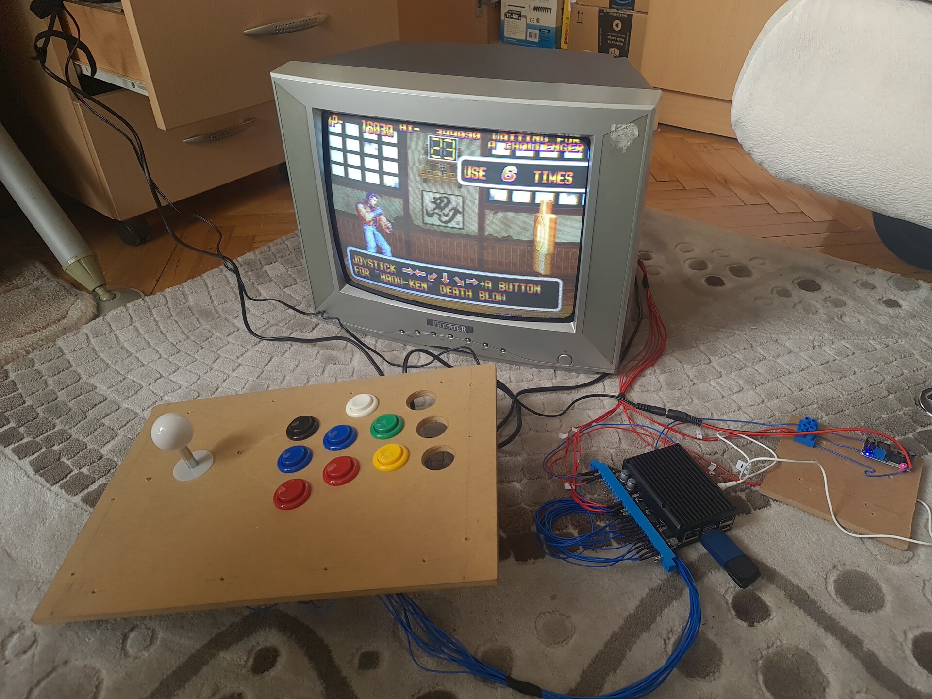
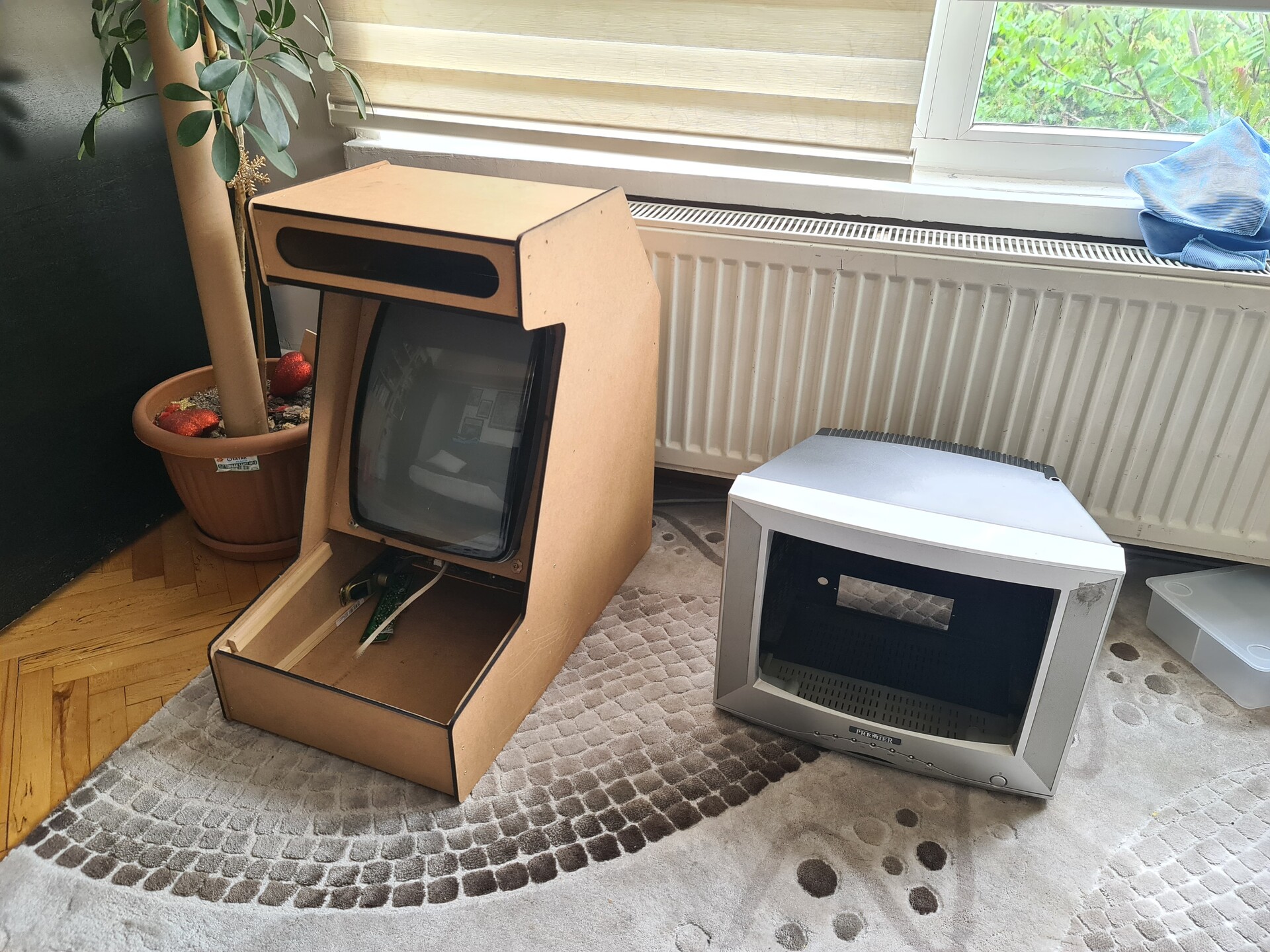
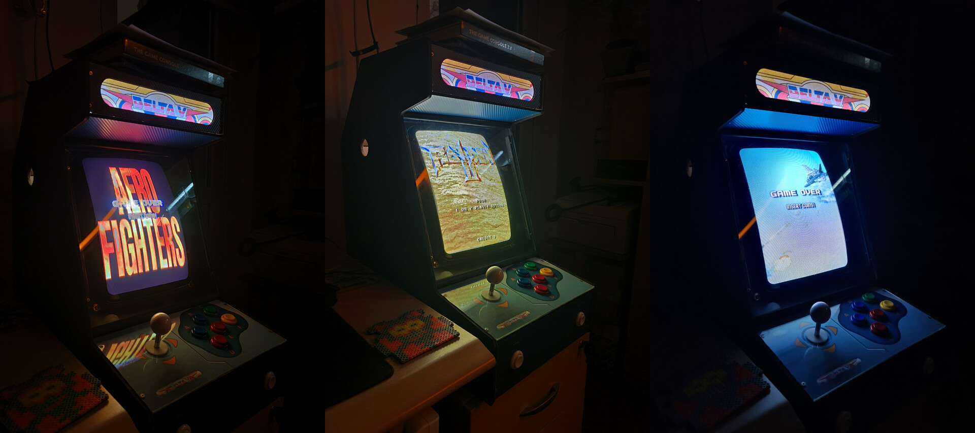
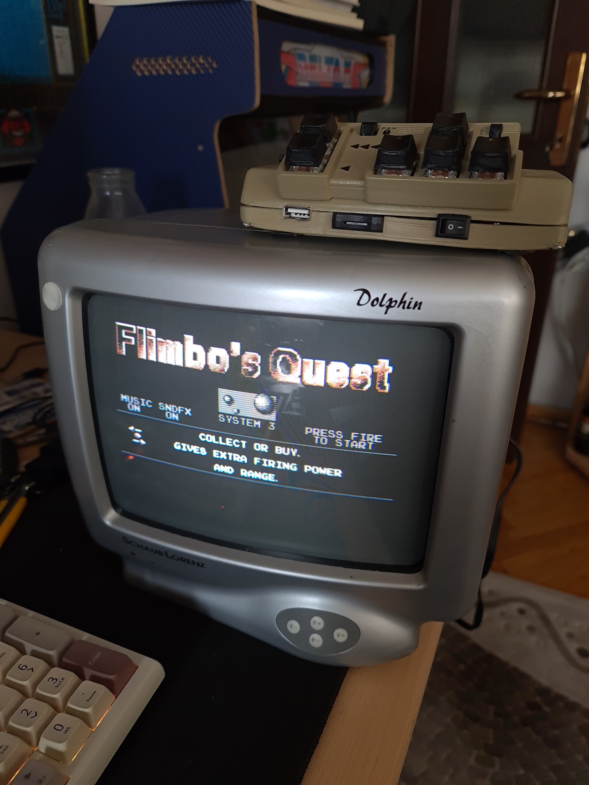
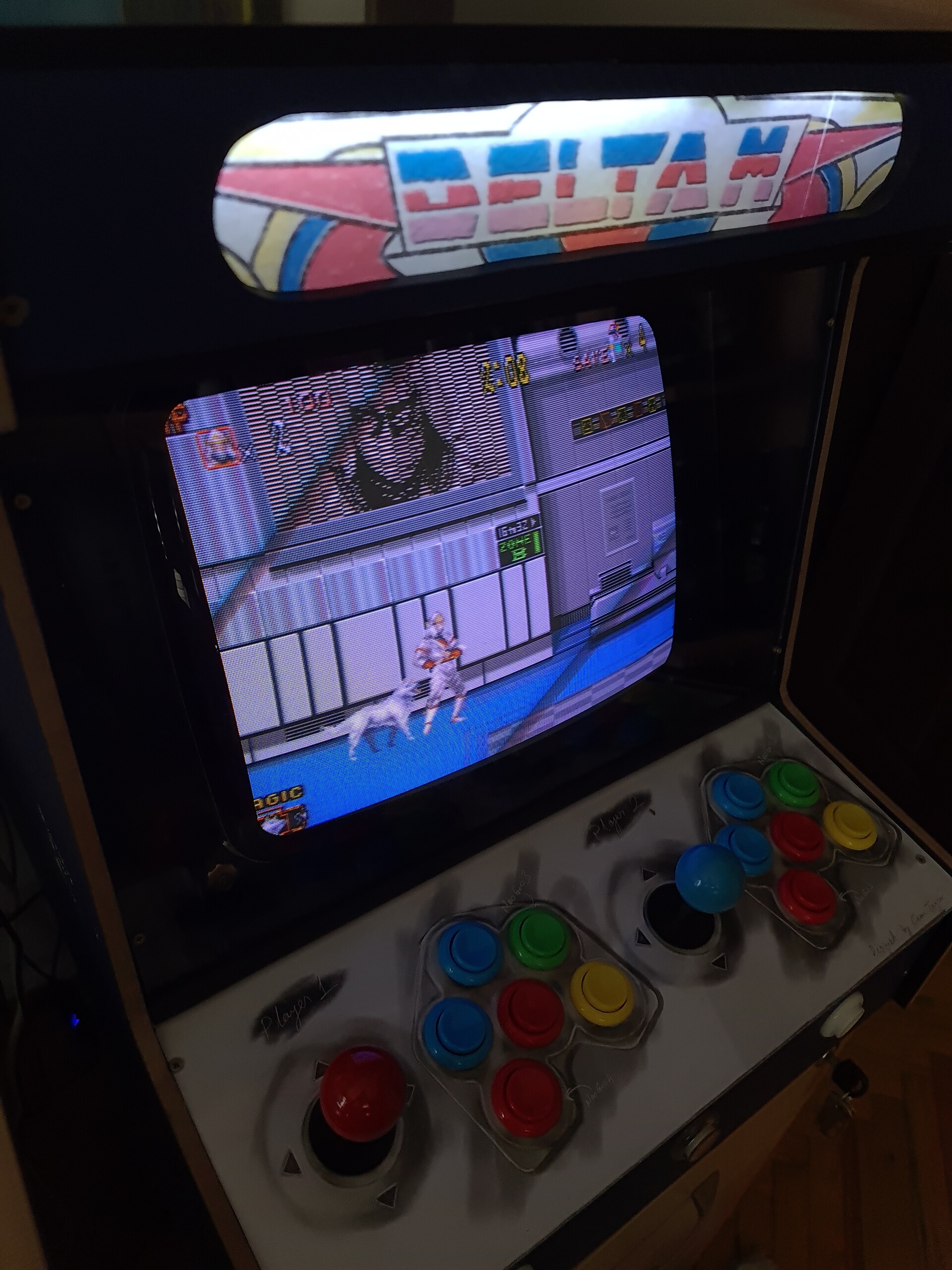
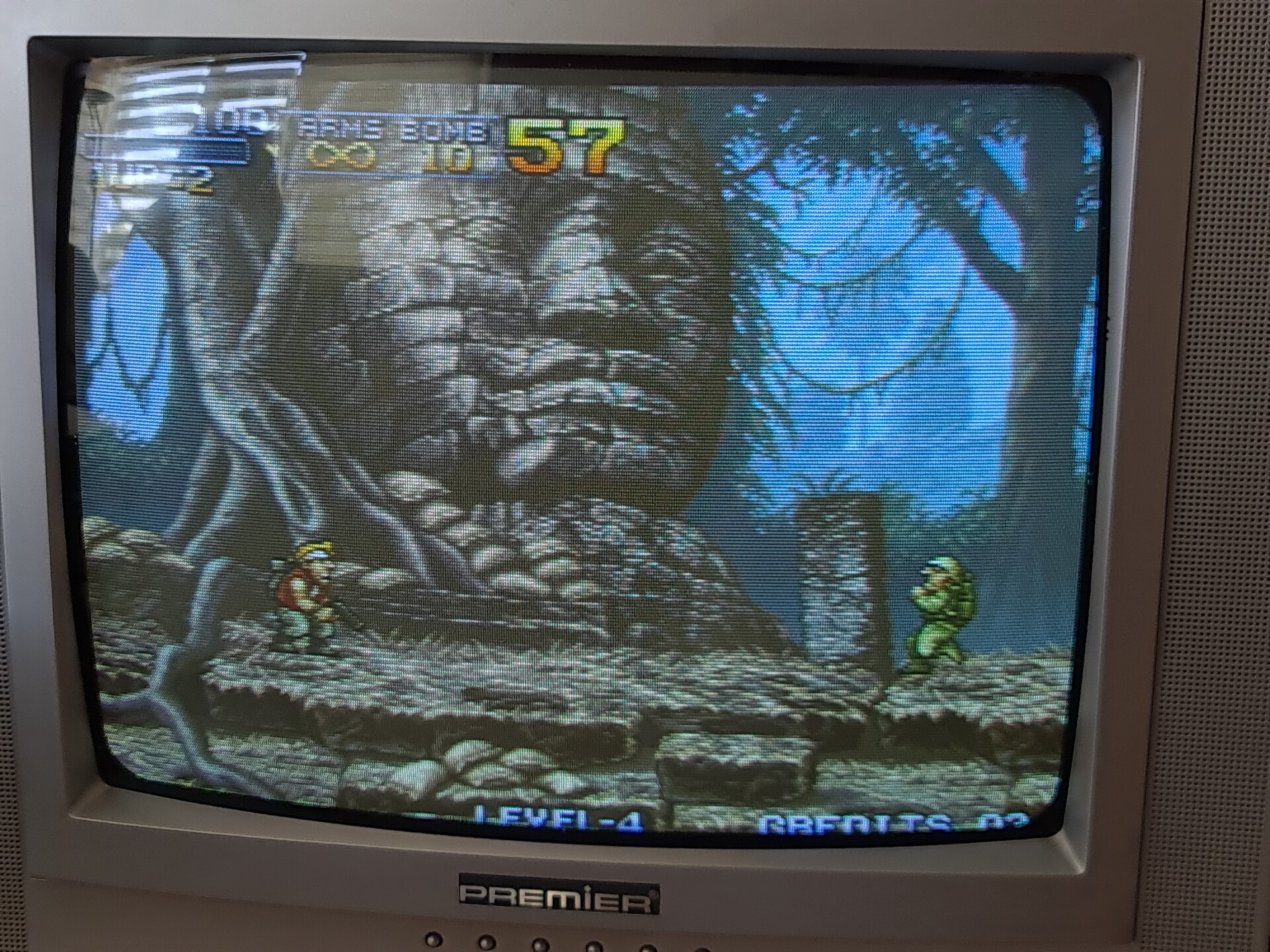
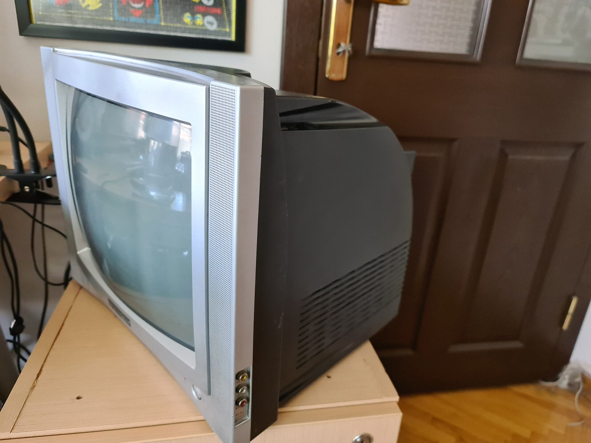
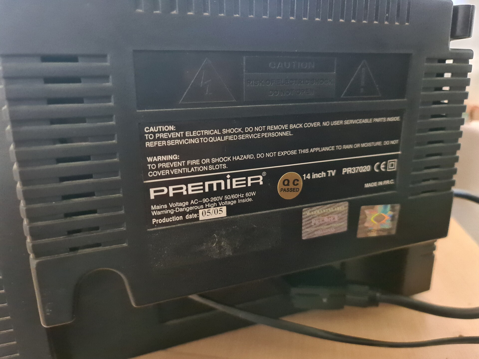
The main purpose of this cabinet was the "Premier" branded CRT TV that I saw in the house of my mother-in-law. It was a 14" CRT TV that show the pixels in a very good way. Also that TV supports refresh rates from 50hz to 60hz. And one the best thing about that TV was that it aligns screensize automatically, I don't know how. 

That TV made me think of creating another bartop cabinet by using that kind of CRT screen since it's small, but had enough size to show the pixels and games.


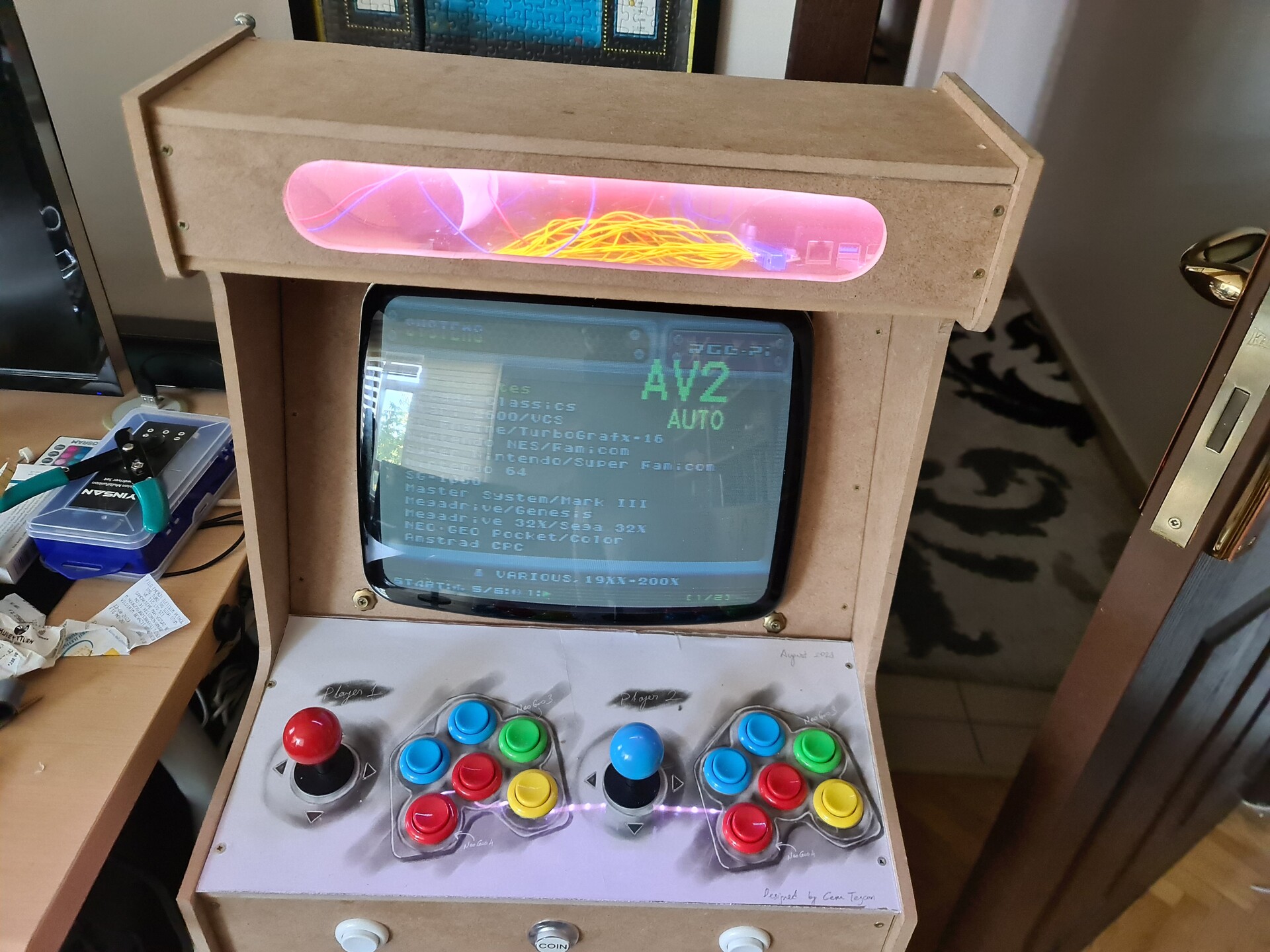
1.2. The Emulator and The Hardware

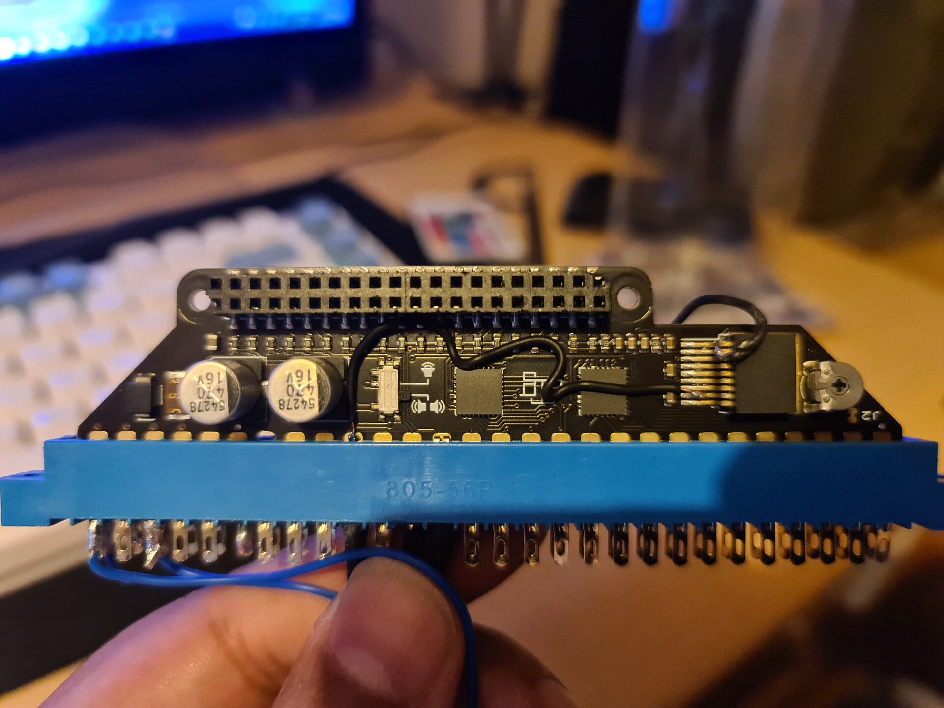
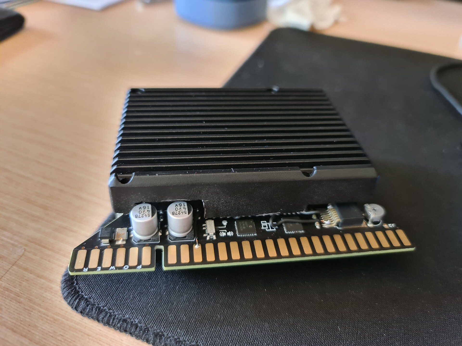
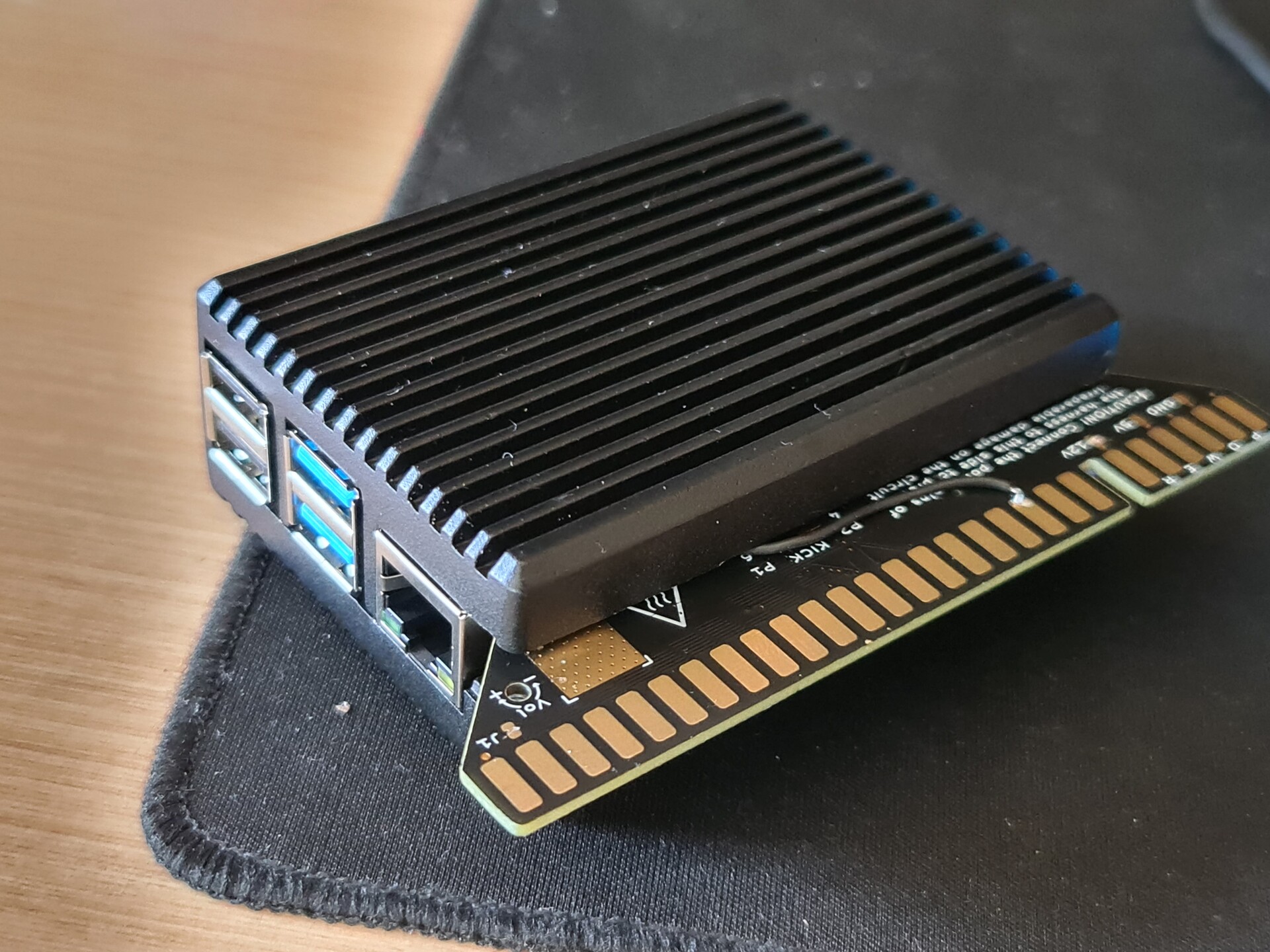
Another component that I had was an "RGB-Pi jamma hat" that can be used on Raspberry Pi devices to emulate arcade games. You can purchase different types of RGB-Pi products by this link: https://www.rgb-pi.com/

Normally if I had a RGB-Pi Scart instead of RGB-Pi Jamma I could connect it directly to these TVs but since my connection type is JAMMA then I needed to convert the jamma signal pinout to scart pinout. 

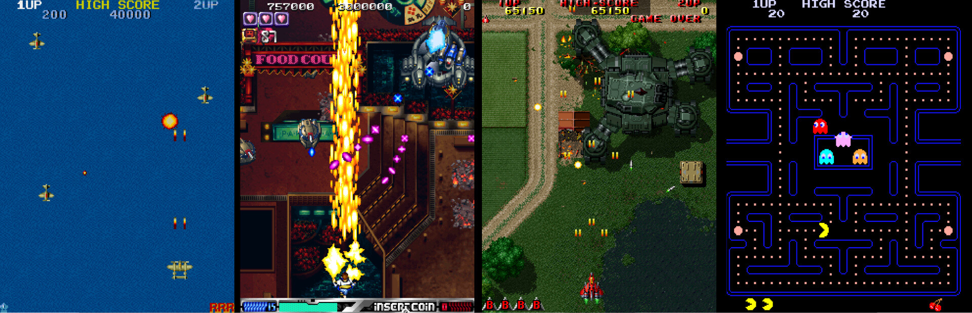
The best thing about these devices, they have a special software that compatible only with this hardware that runs the games in various refresh rates fixed to the original rate of the arcade game that you play. This part is the real tricky and one of the most important part on arcade game emulation. Because with modern equipments, we're playing those in a wrong speed. Every arcade game back in time had a specific refresh rate. Here are some examples:

  • Street Fighter II - 59.637405 Hz
  • Shadow Dancer - 57.230000 Hz
  • Mortal Kombat 1-2-3 - 54.706840 Hz

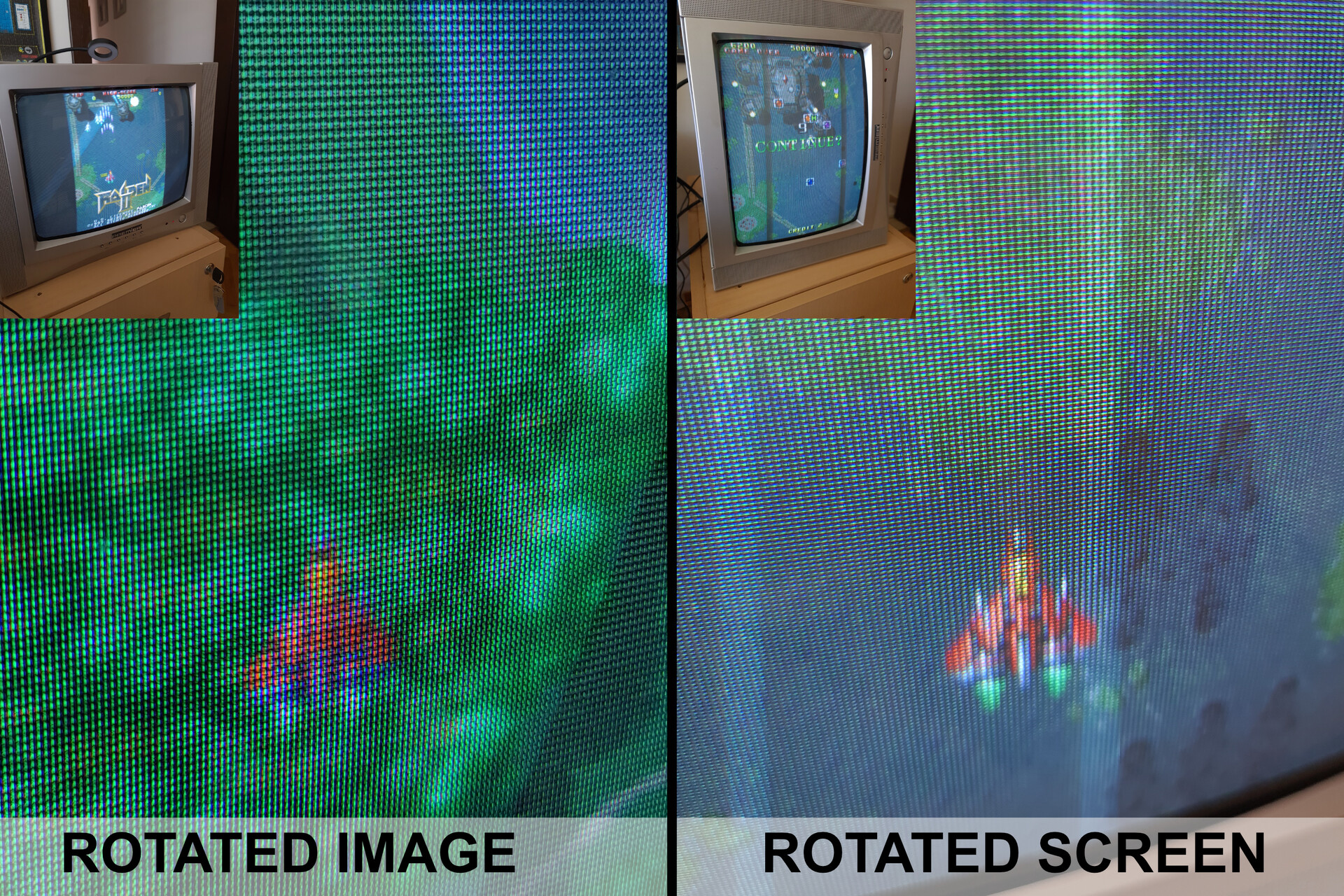
Consider these values as FPS of those games. But once you play those games in a PC, PSP, PS Vita or Retropie etc. you have a fixed 60 fps refresh rate. Thich means for the sake of smooth scrolling, emulator shows more frames than the actual framerate of the game. you play Mortal Kombat 9.6 percent faster than you used to be in 90s. Shocking, eh? Check this video.


Original refresh rate can only be achieved on a proper CRT screen with a proper sync signal which is generated by a proper raspberry pi device with a proper emulator. So my electronics setup is formed. 

2. JAMMA to SCART Conversion

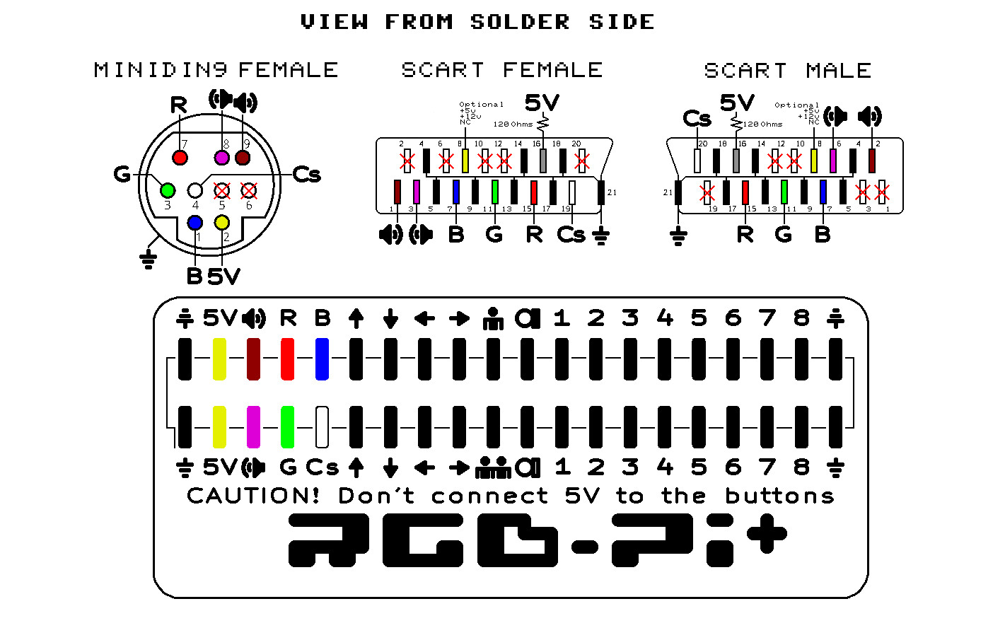
Only problem was that my RGB-Pi hardware was JAMMA version. So I needed to make a convertion from Jamma to Scart. Because SCART is the easiest and the best connection for the TVs which is analog RGB.

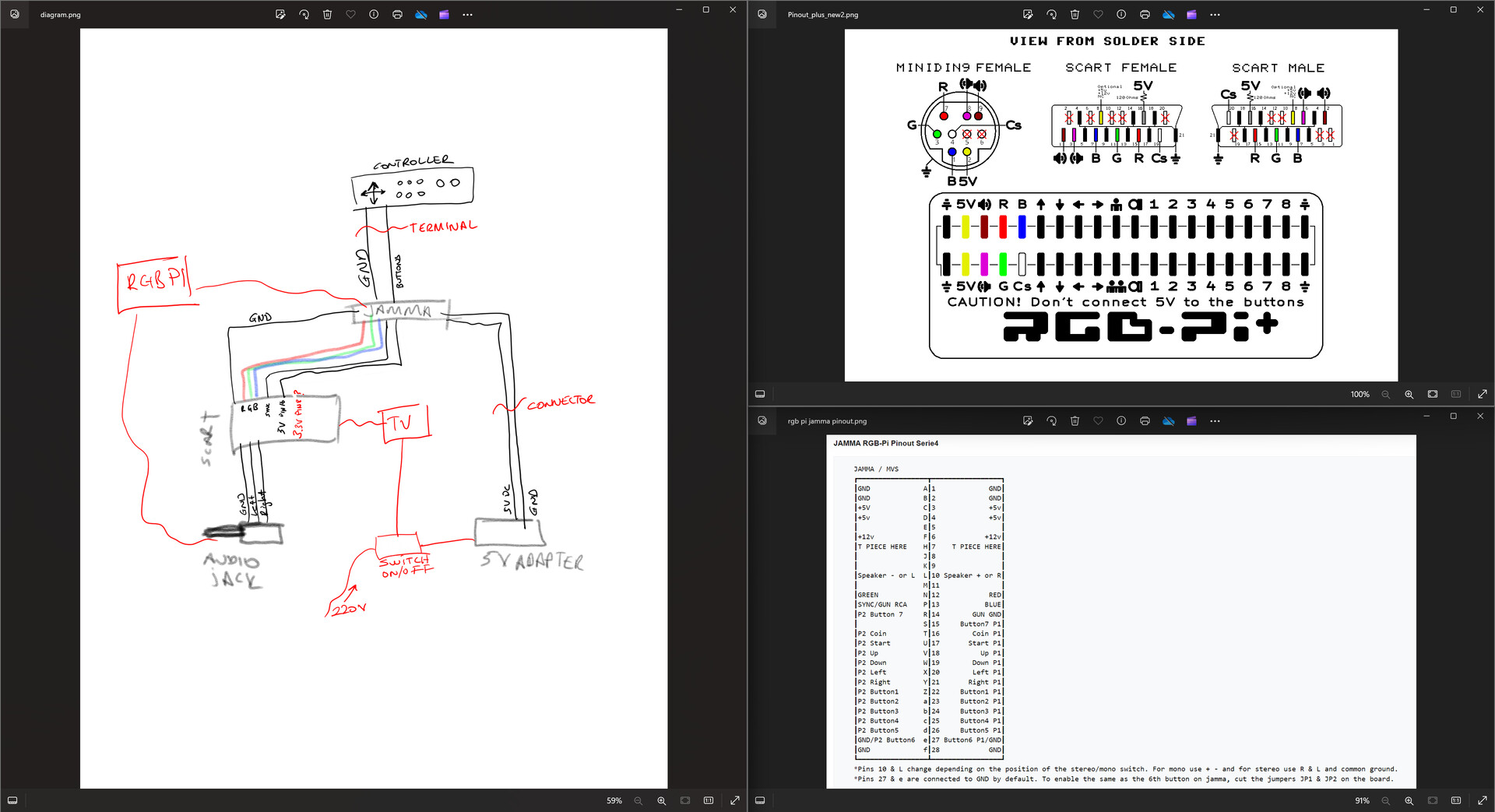
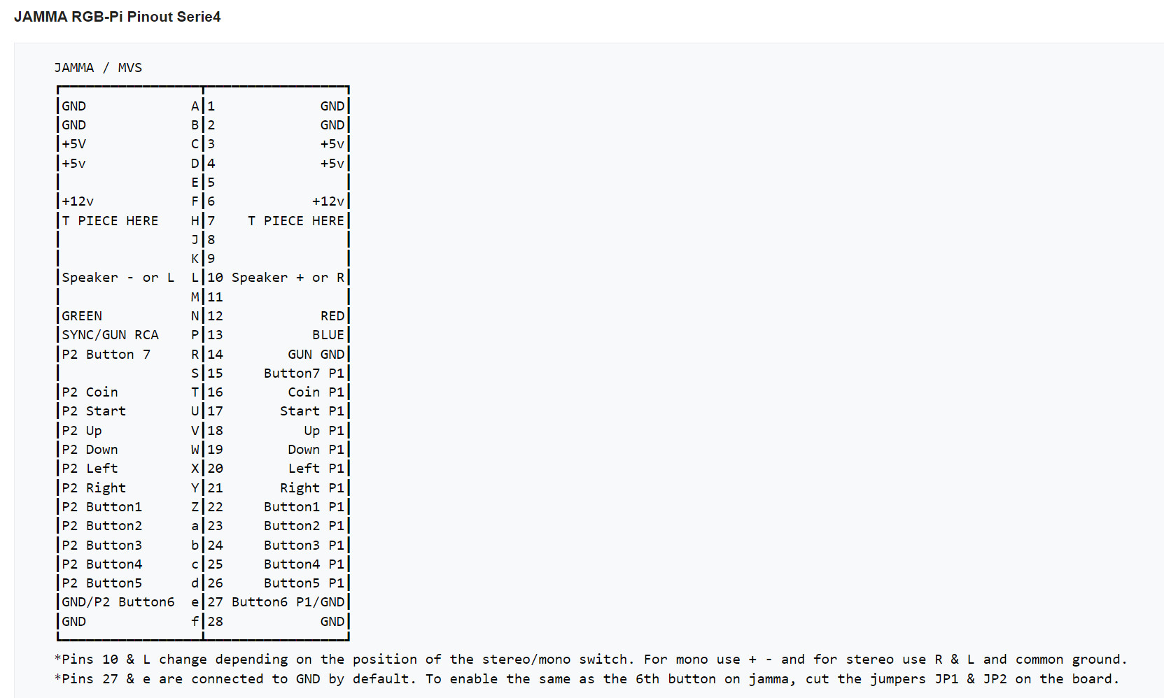
I followed this two diagram and applied it between a jamma connector and a female scart connector. 


Source: https://www.mortaca.com/rgb-pi/wiki/index.php?title=RGB-Pi_JAMMA_Installation/en

Source: https://www.mortaca.com/rgb-pi/wiki/index.php?title=RGB-Pi_PLUS_Installation

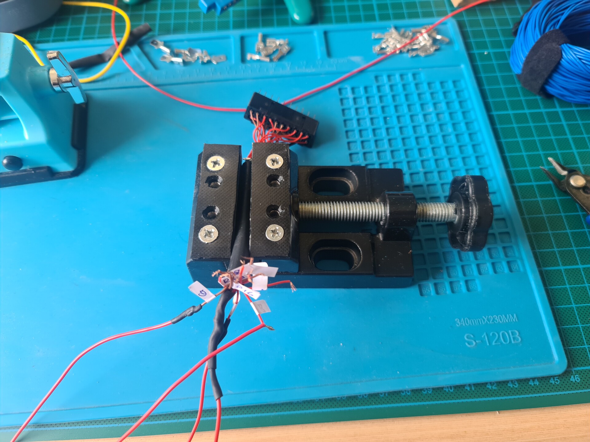
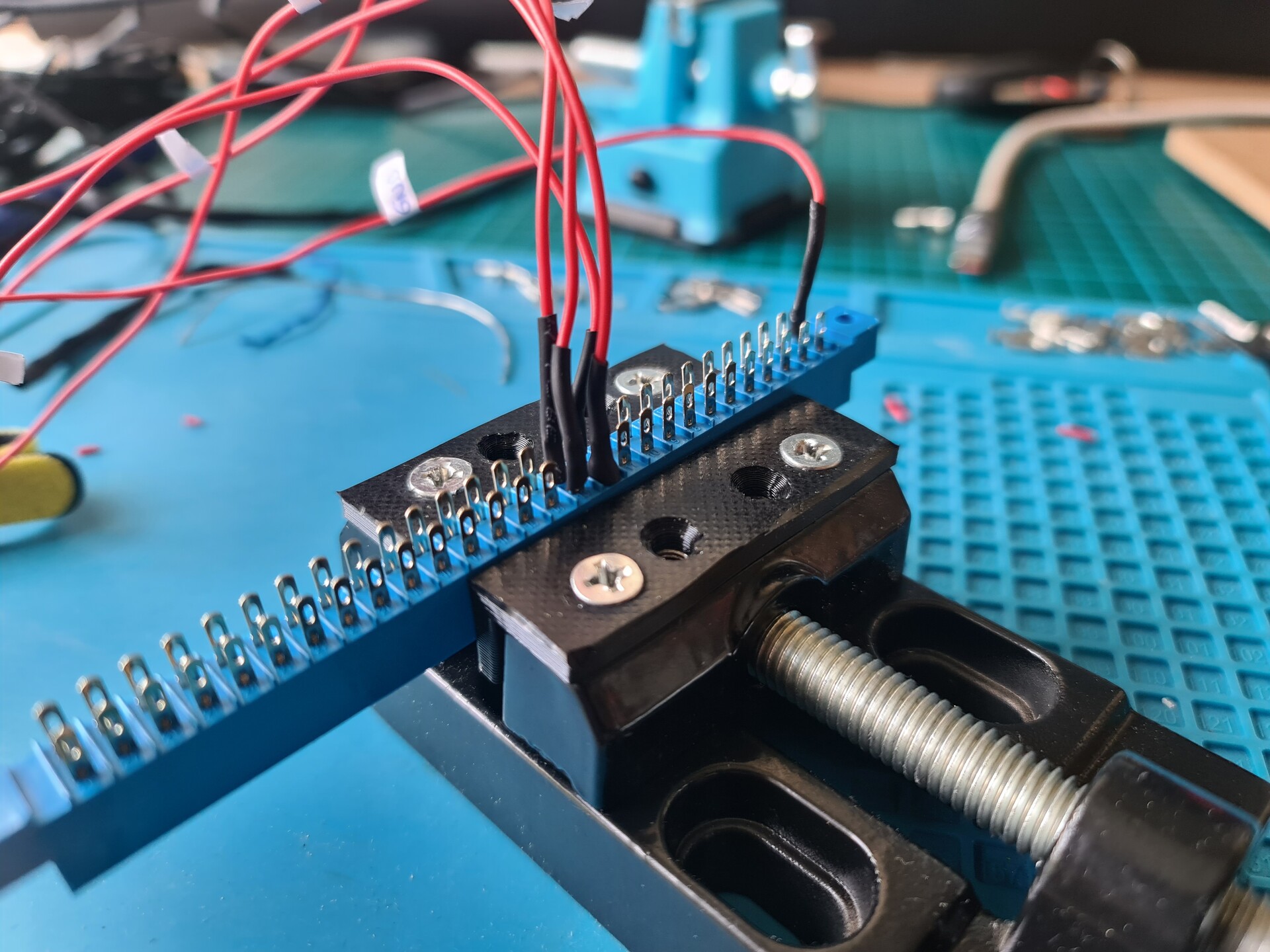
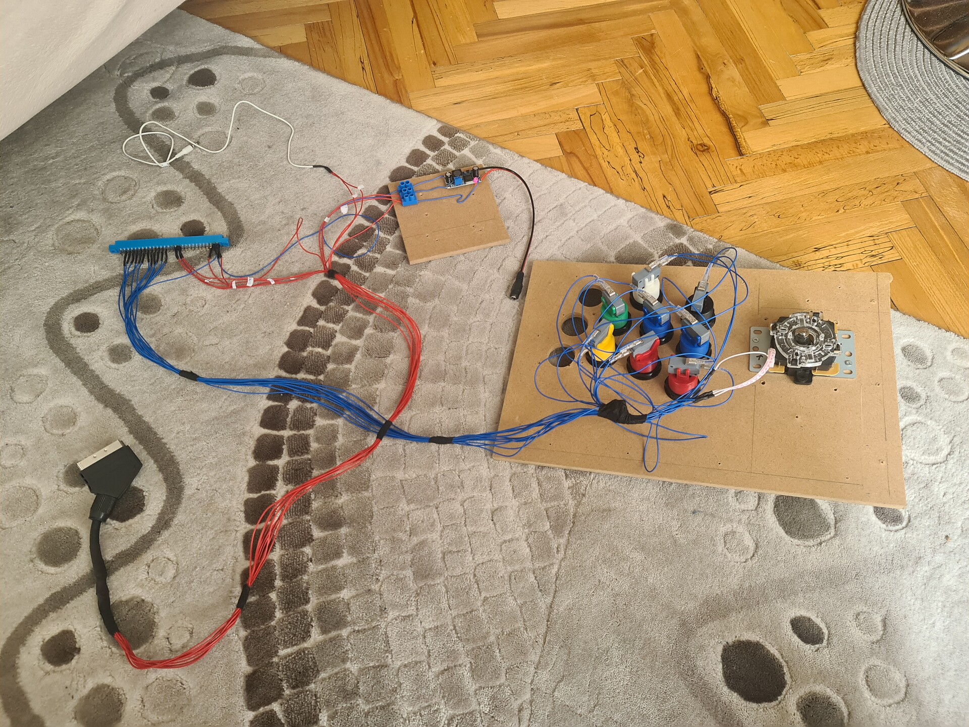
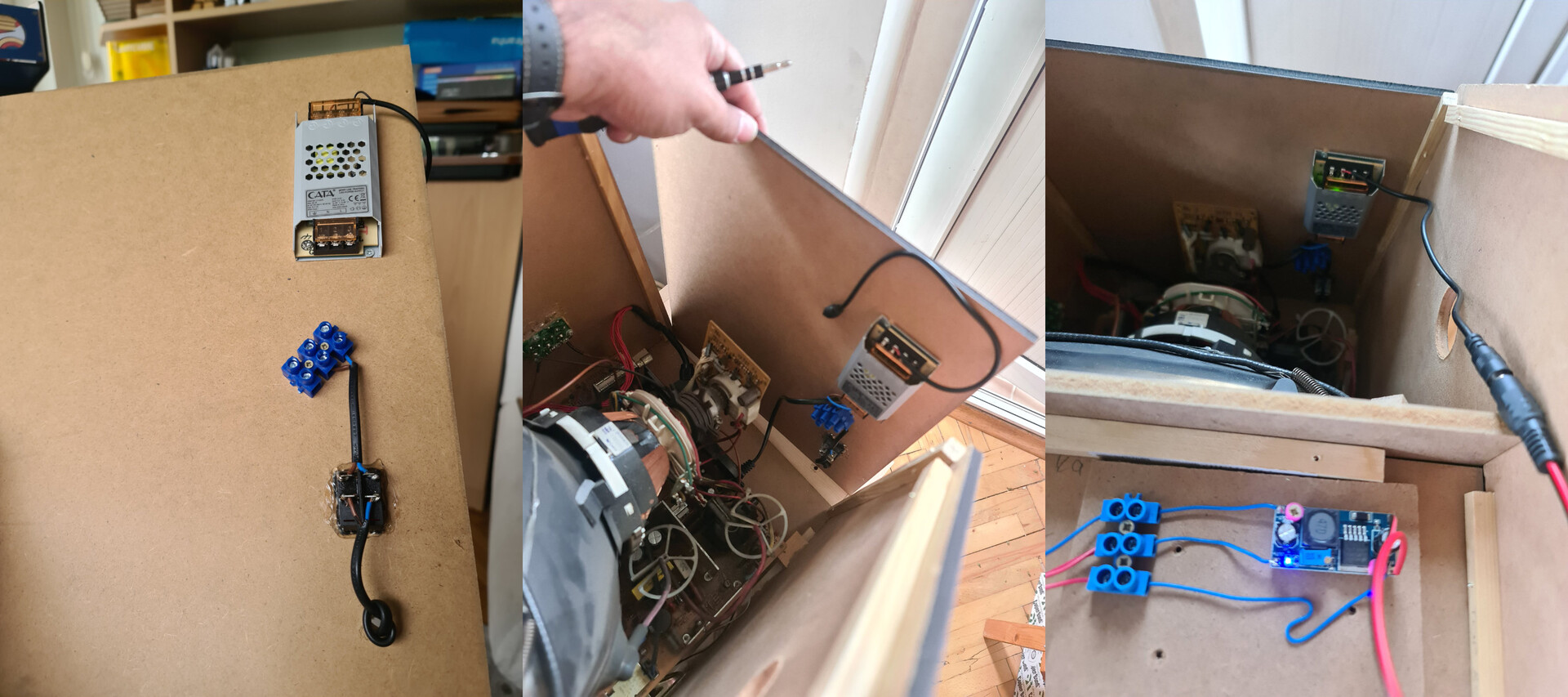
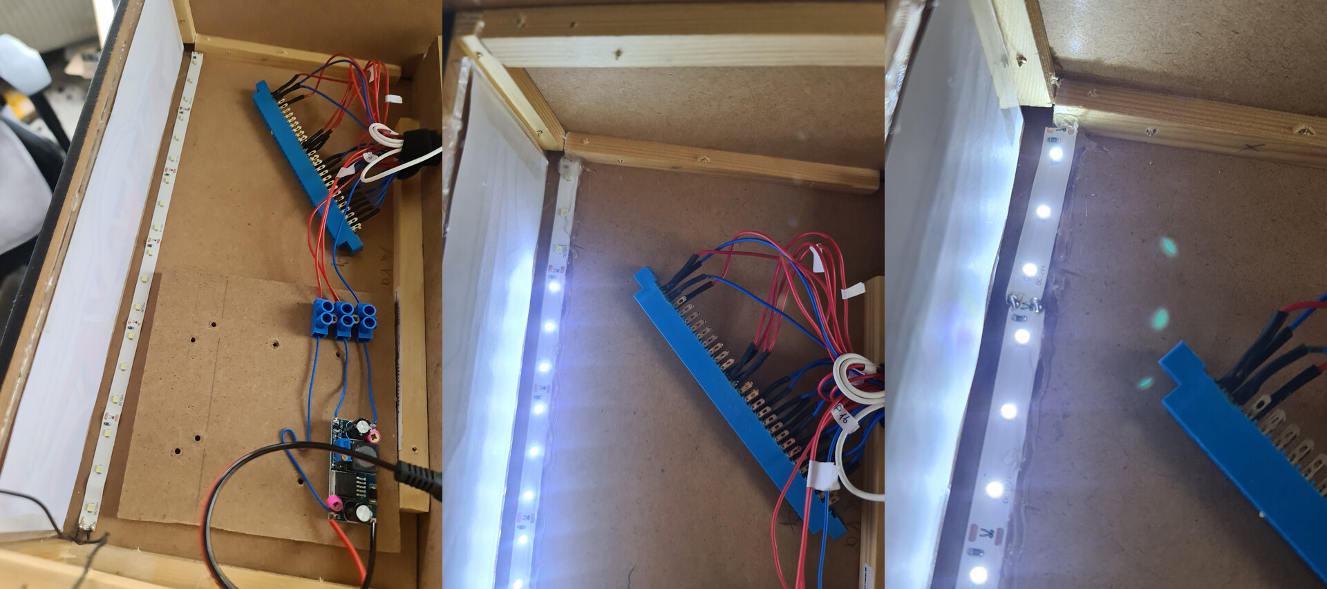
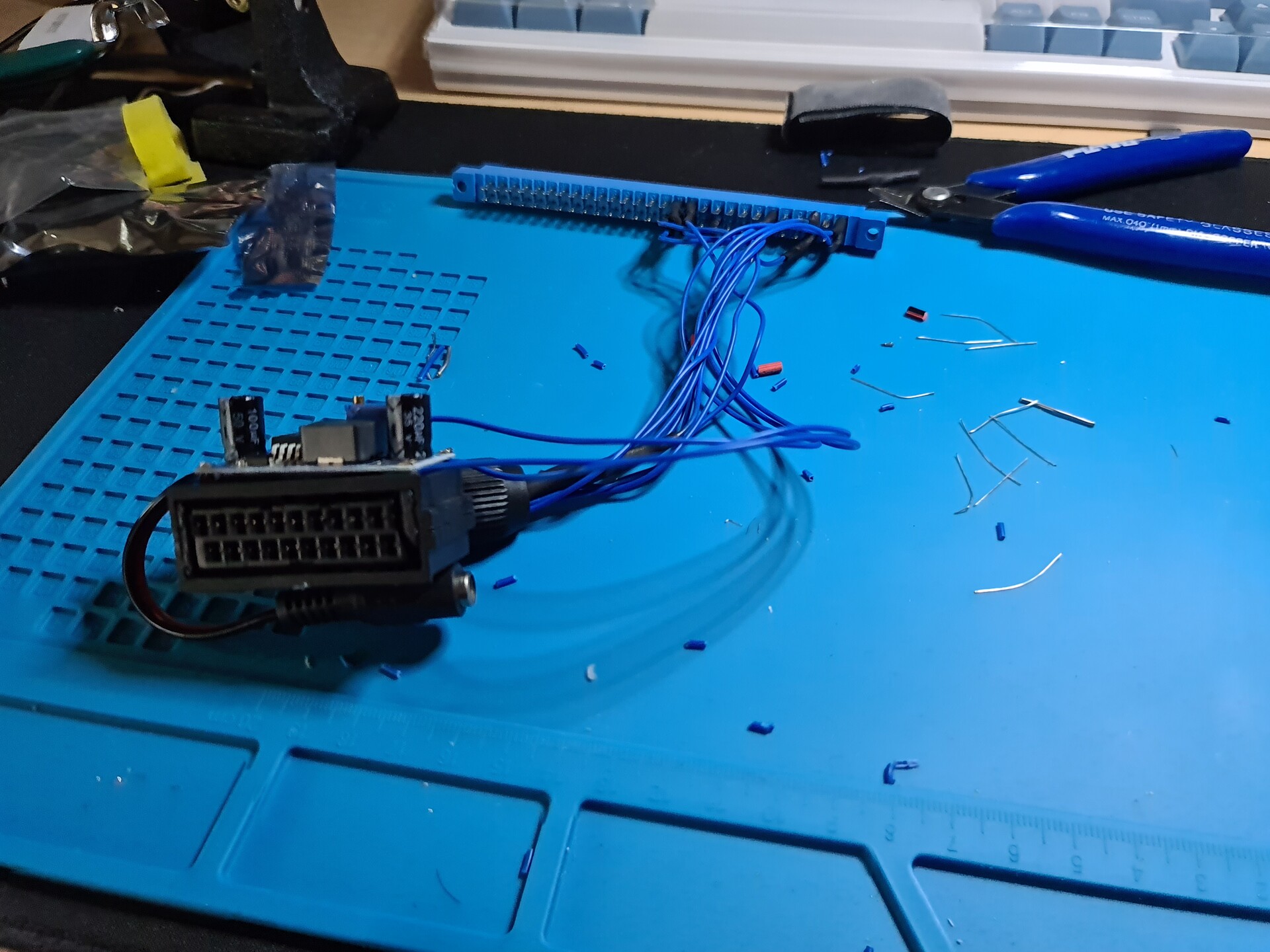
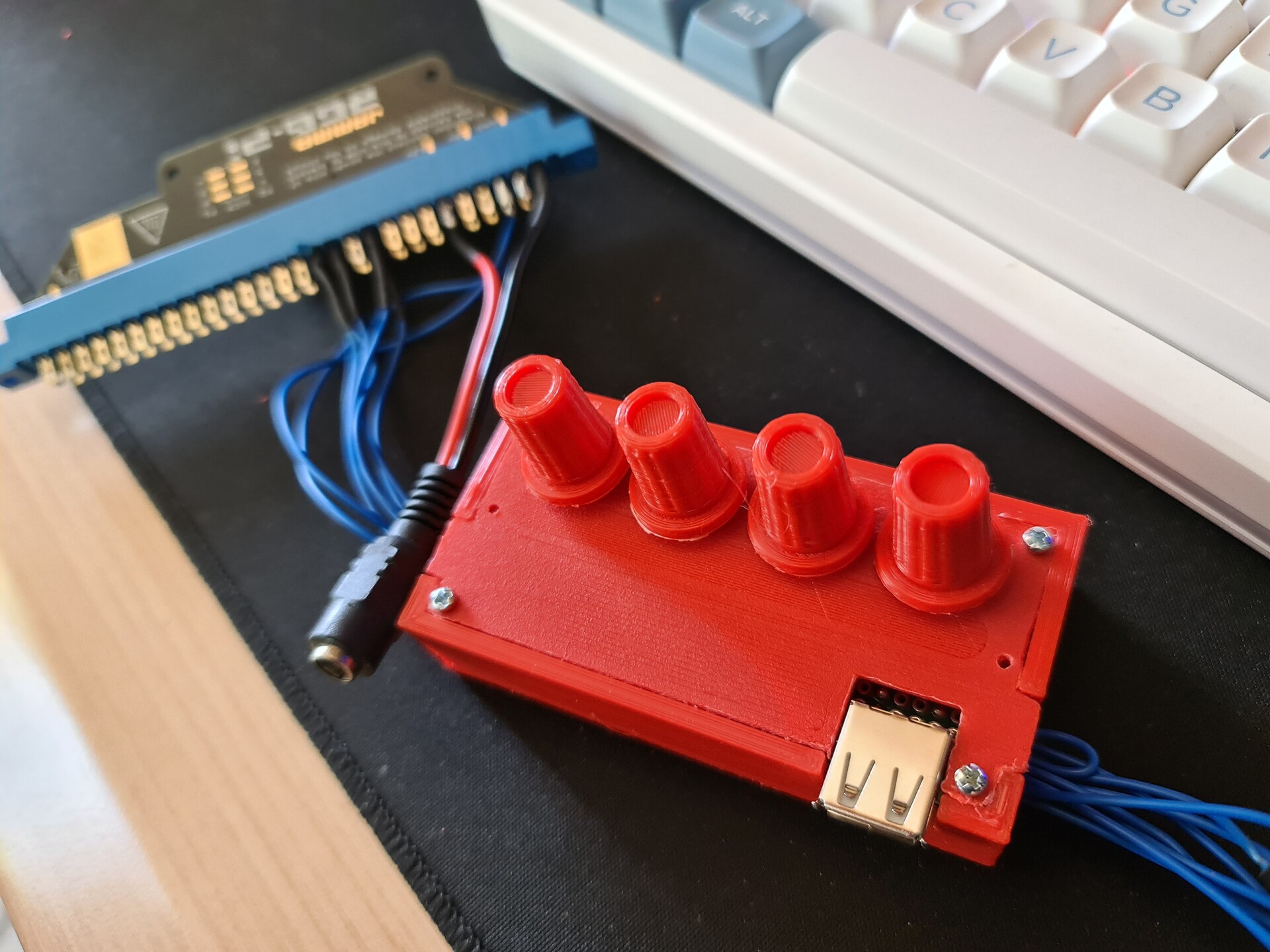
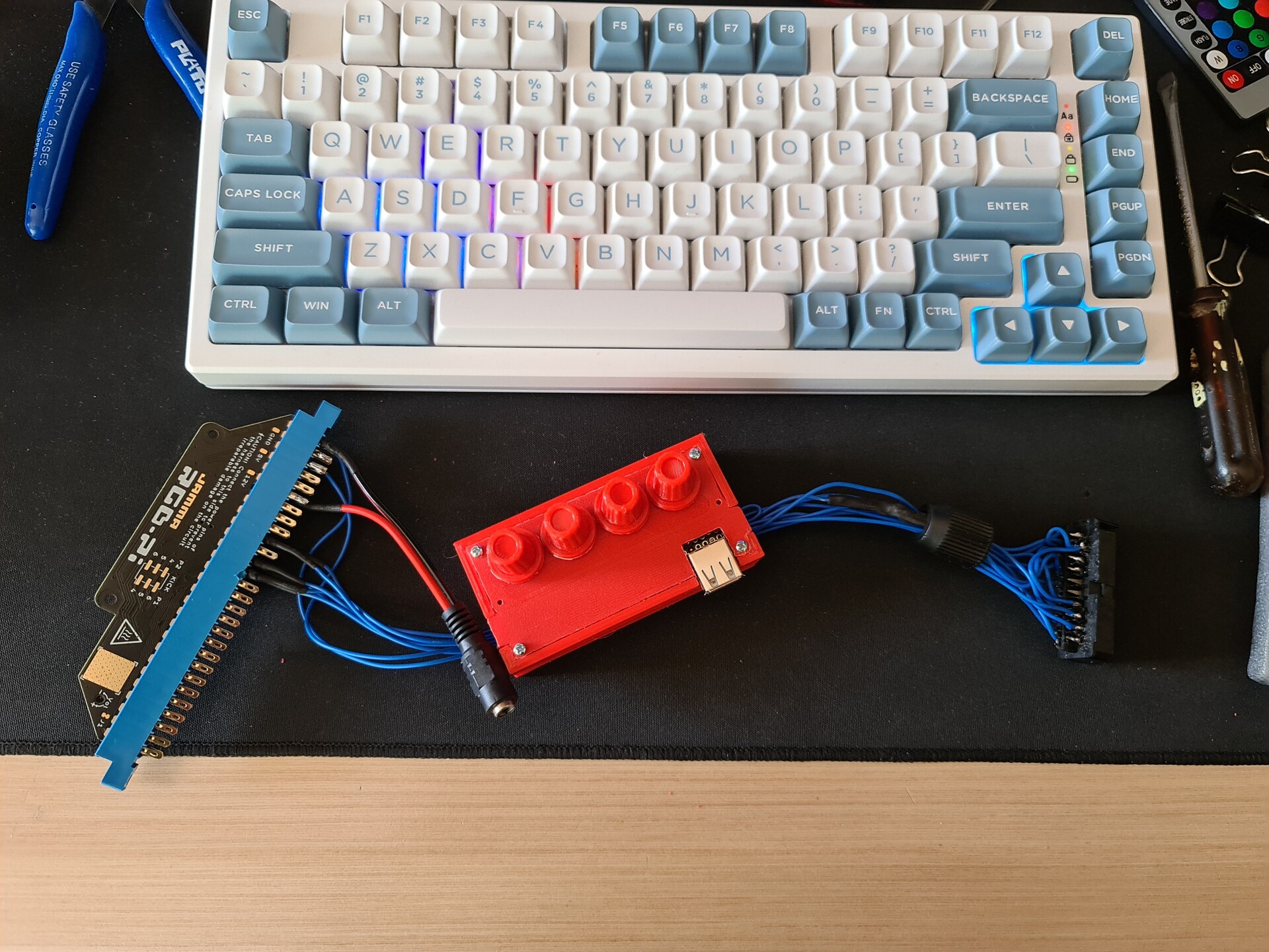
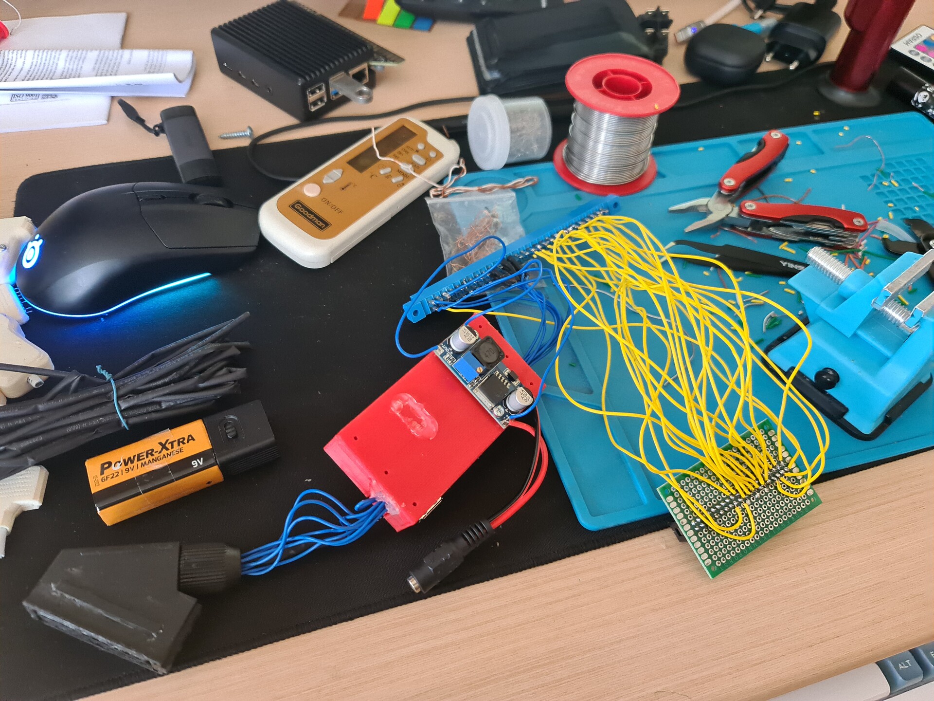
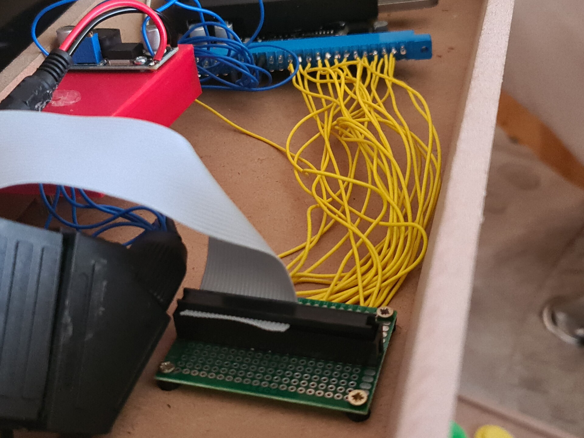
Pinout is pretty easy. Also the Jamma Connectors need to have both 5V and 12V input. So I used a LM2596 DC-DC step down module to output both 12V and 5V through a single 12V adapter. 

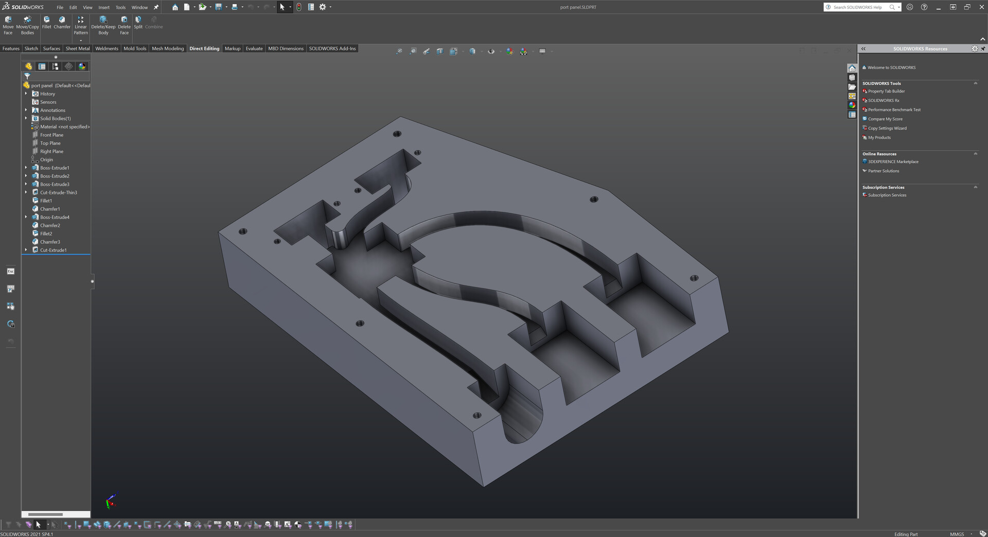
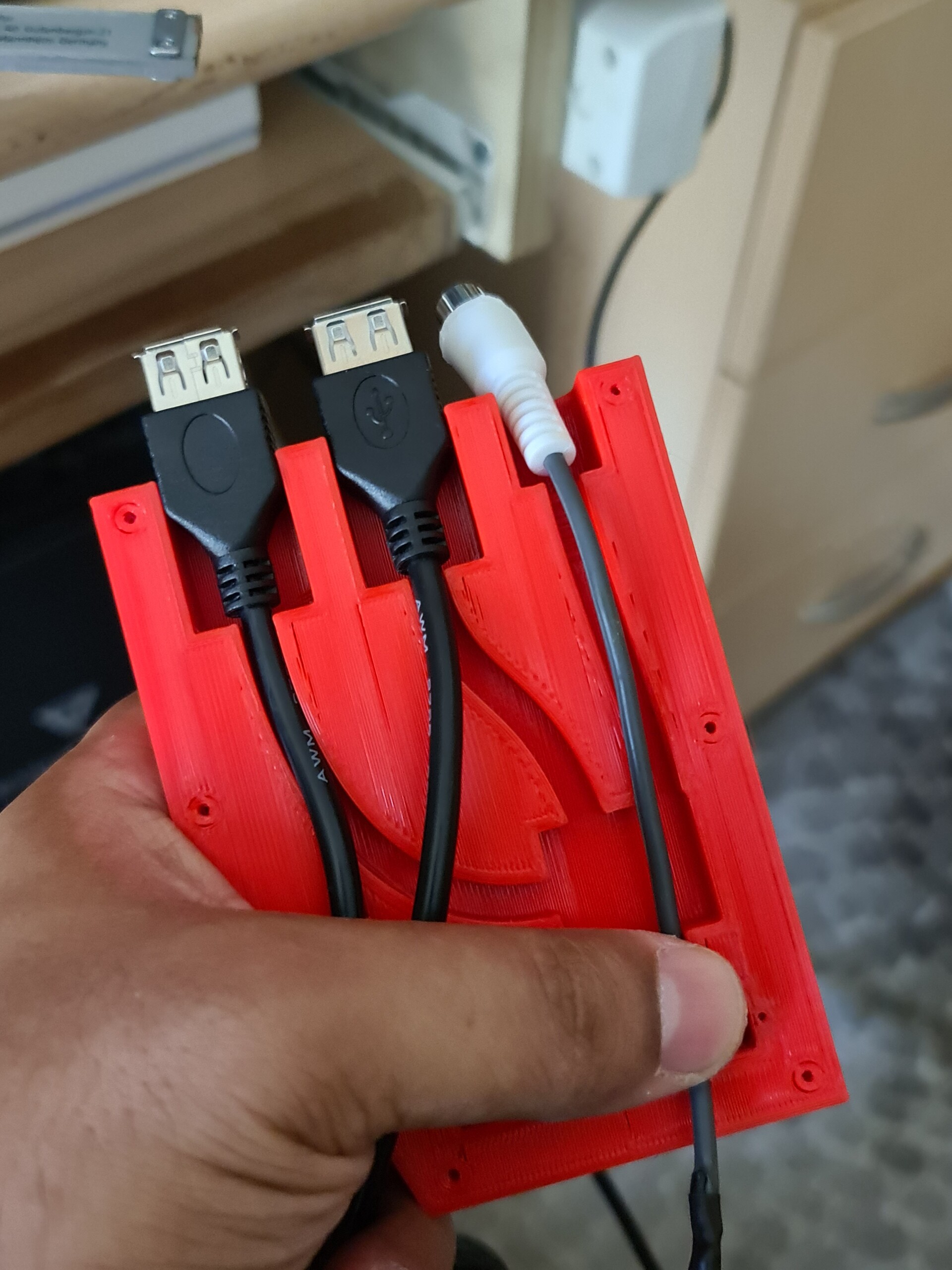
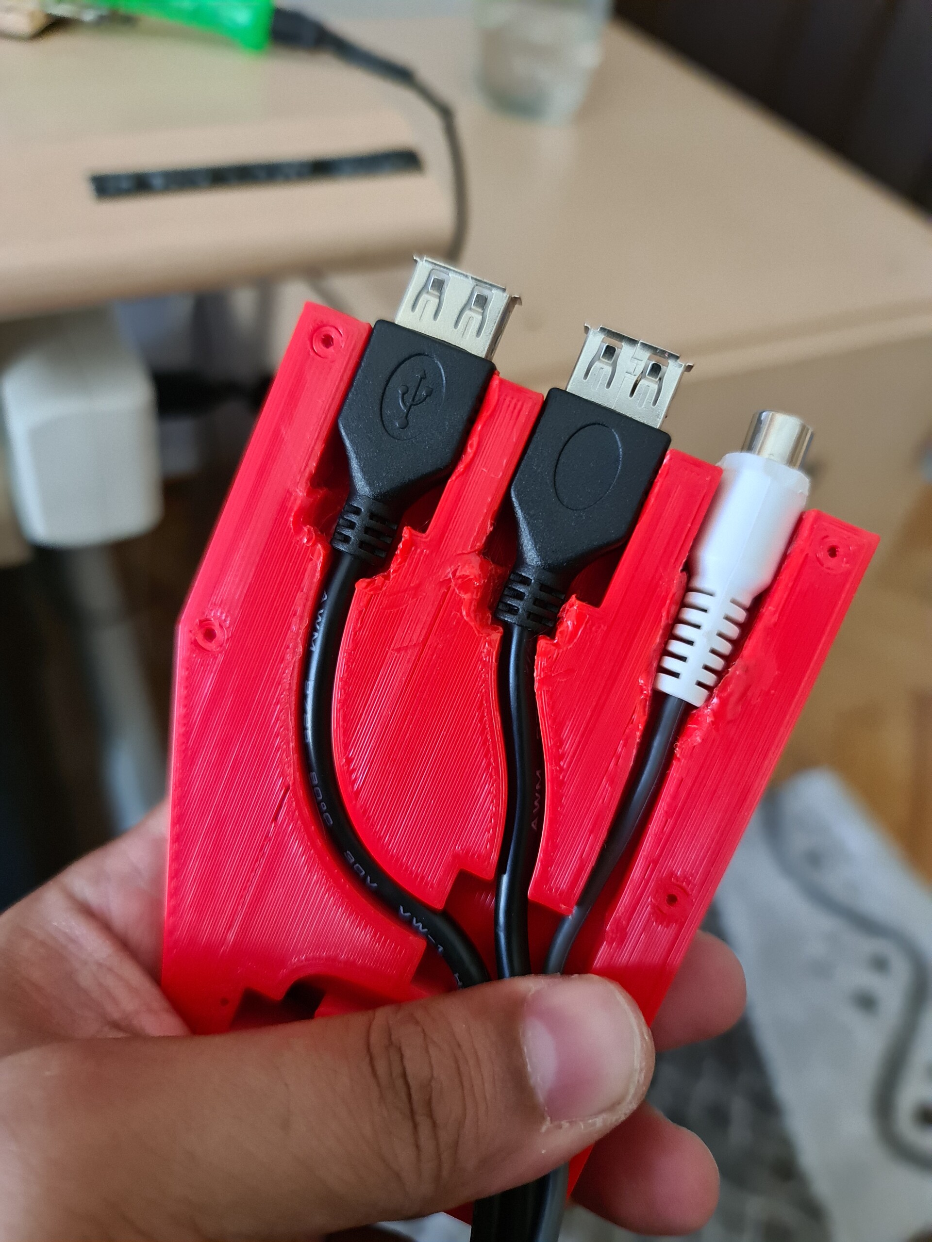
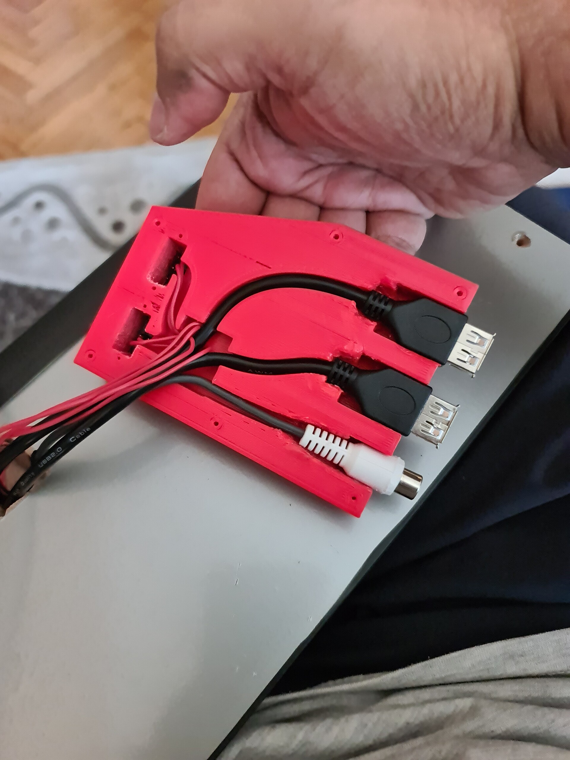
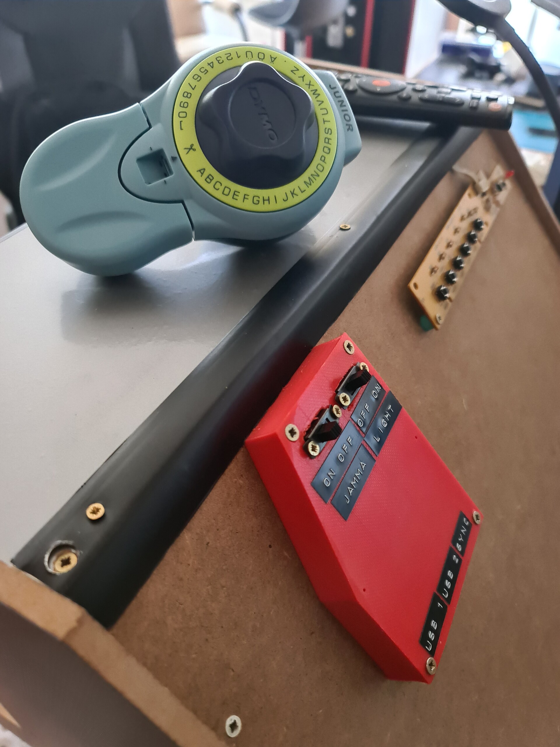
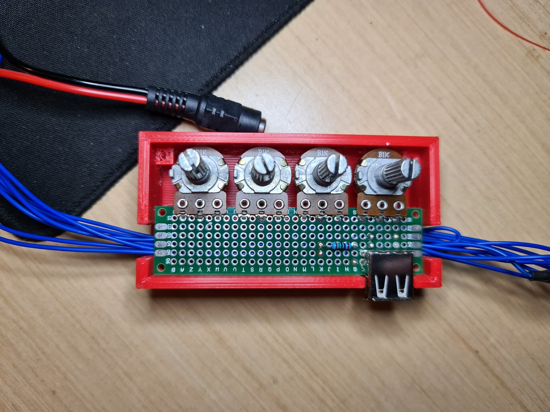
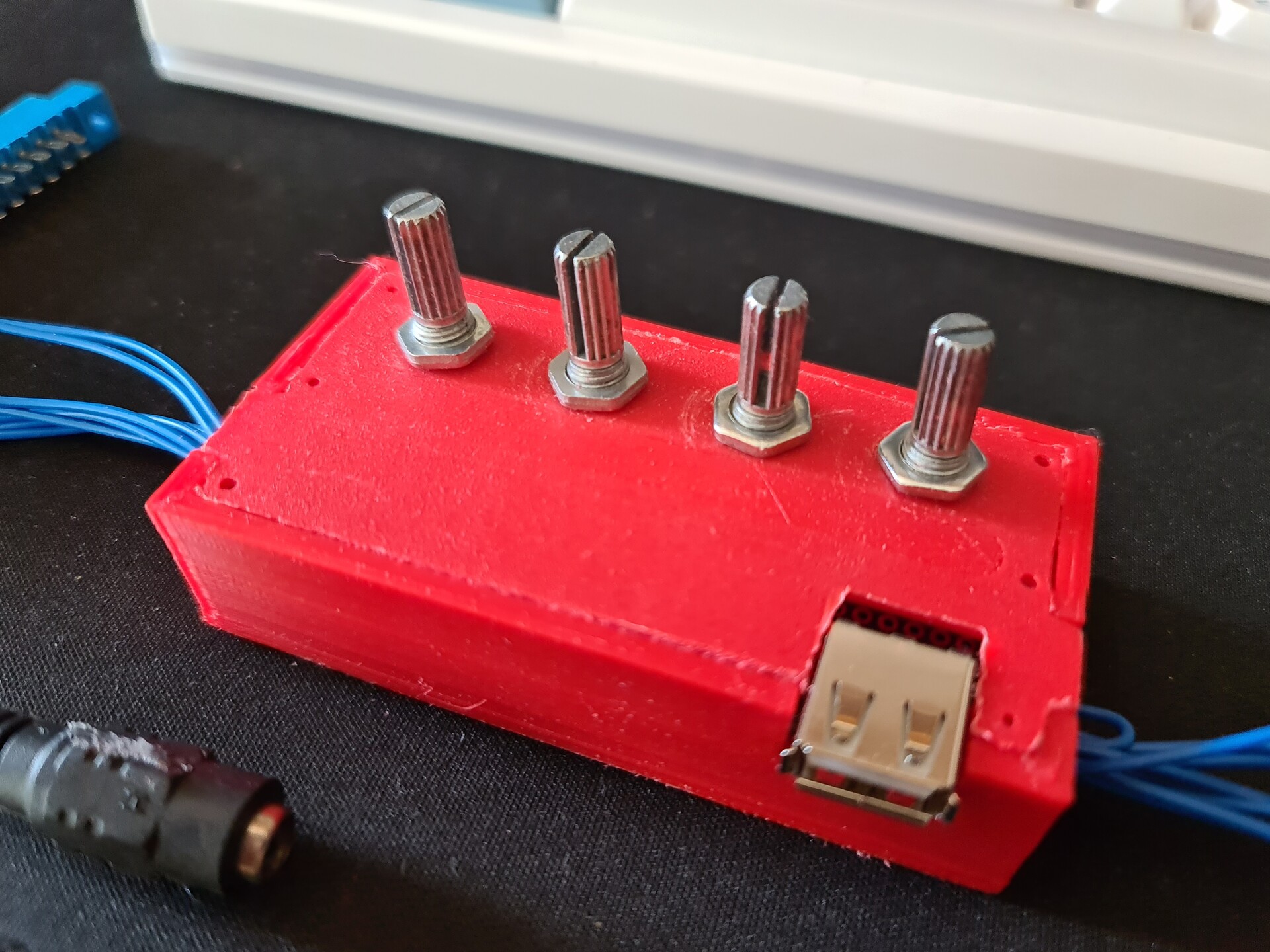
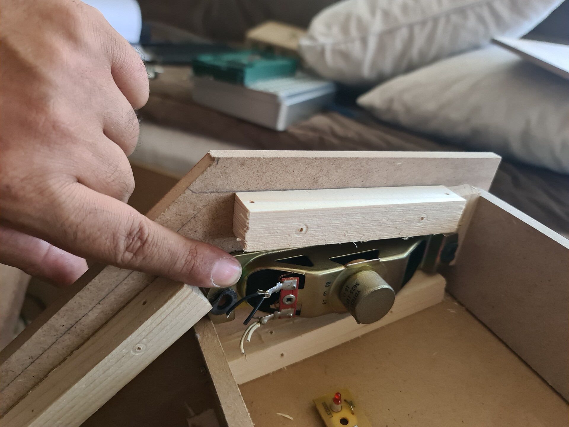
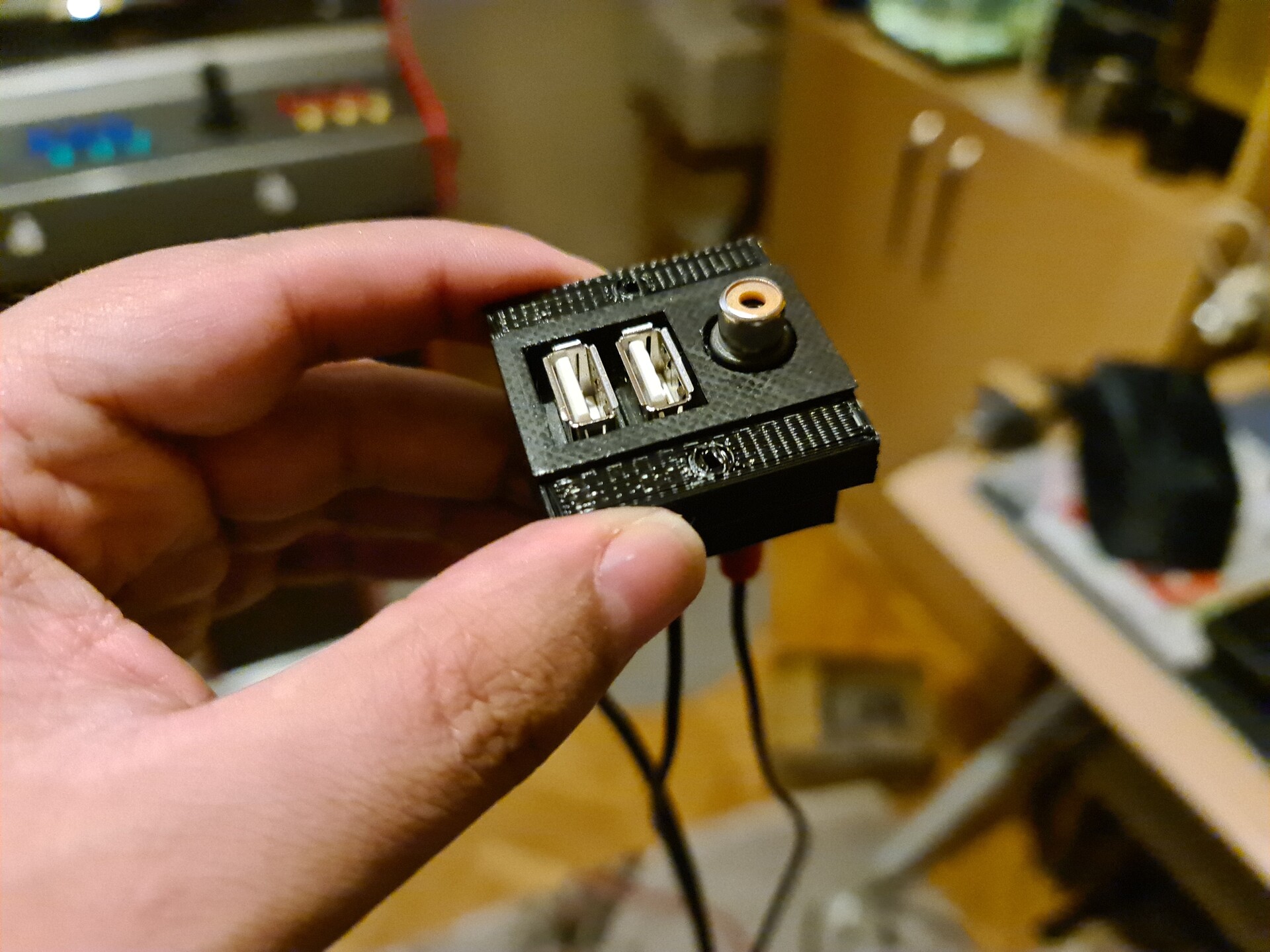
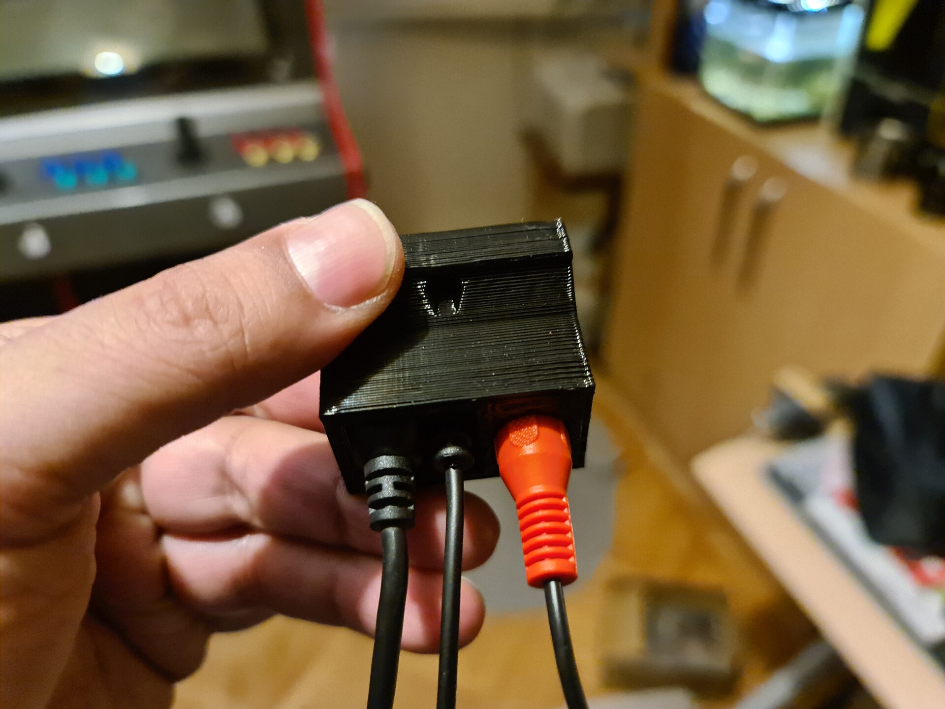
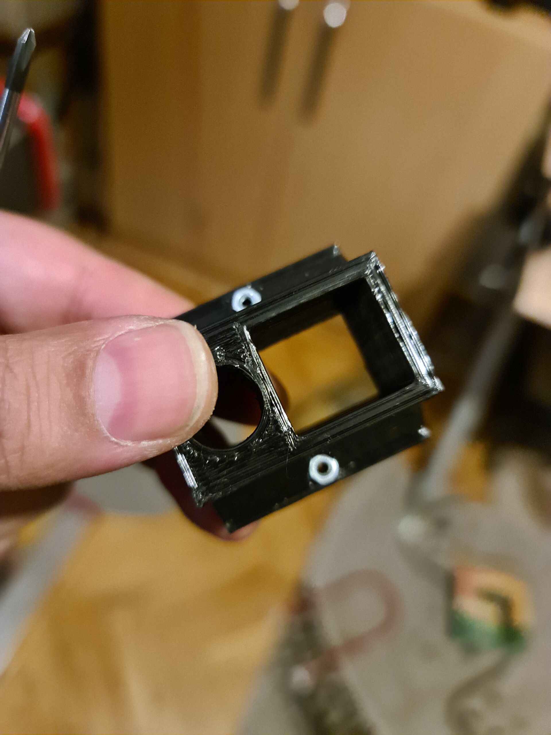
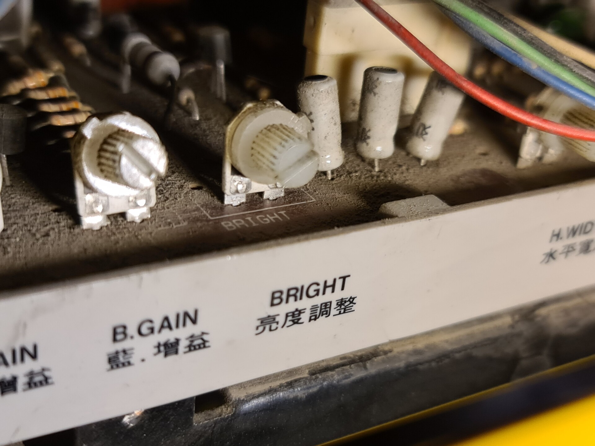
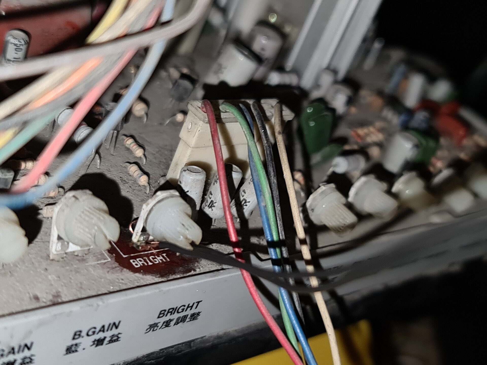
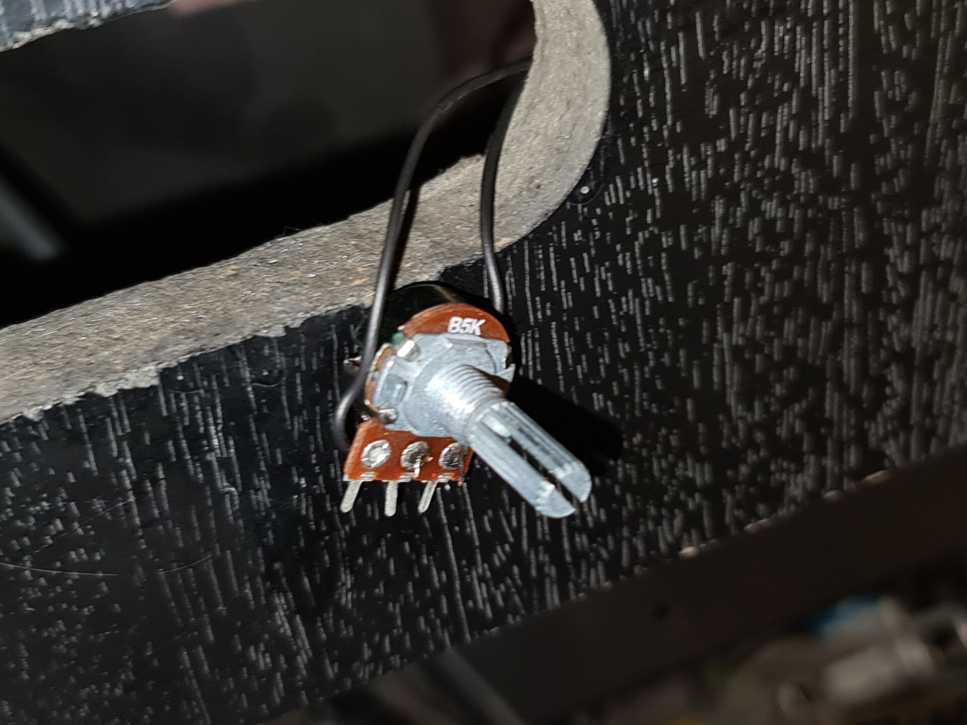
After testing the pinout, I added 4 potentiometers to adjust R G B channels for better picture and adjust the Sync signal for for supporting different arcade systems. After that I designed a case for that little adjustment board where I also added a USB port to connect additional devices in the future.


When I was testing this piece, I accidentally burned the IC on the RGB-Pi circuit. That IC was an amplifier for the sound channel. But this is only needed if you connect the cound channels on a blank speakers. Since I was connecting my sound output to a TV, and the TV has it's own amplifier on its board, I just shot circuited sound channels directly to sound pins of the Jamma edge connected, which means I bypassed that burnt amp IC. 
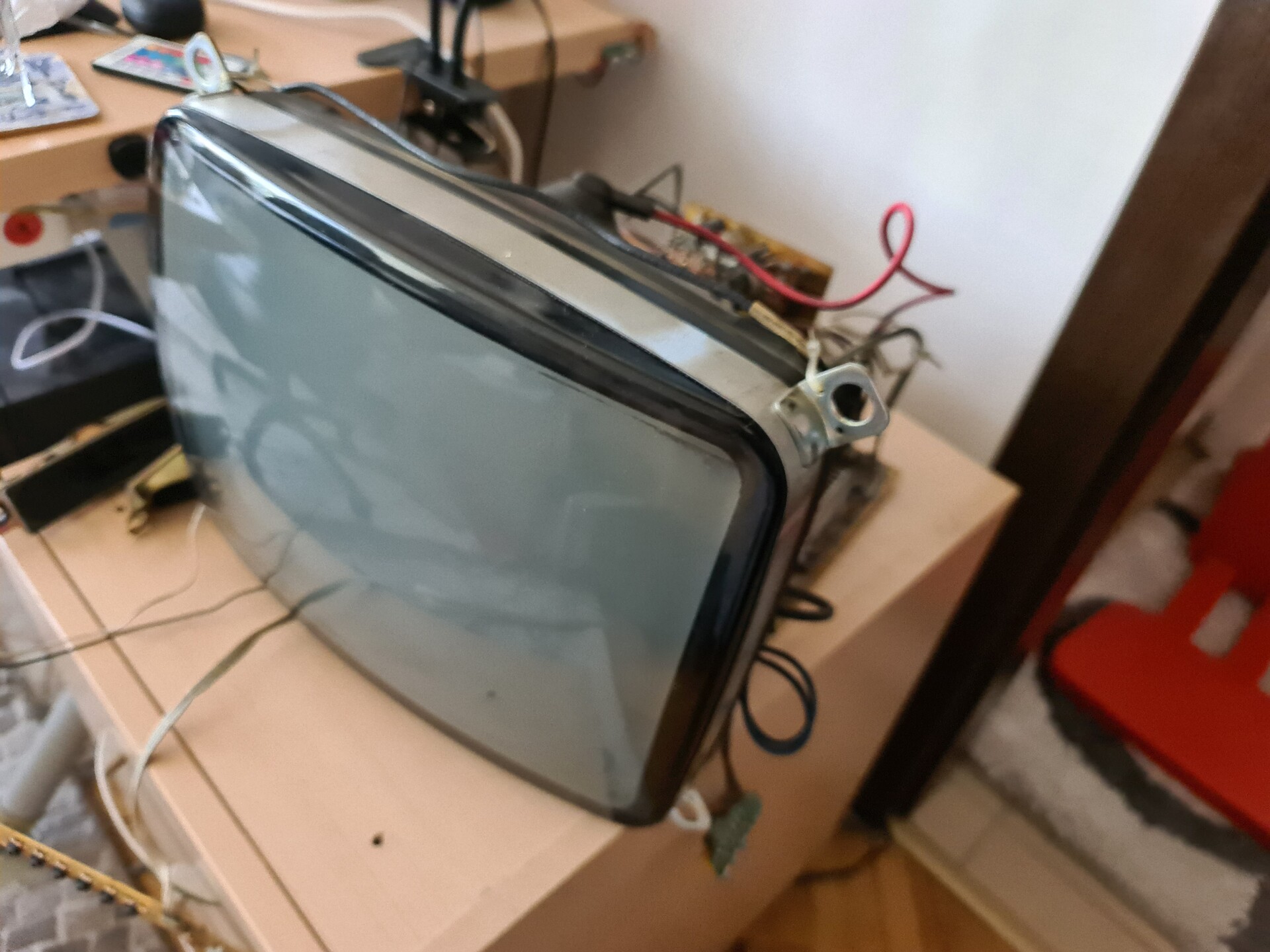
3. Acquiring the TV

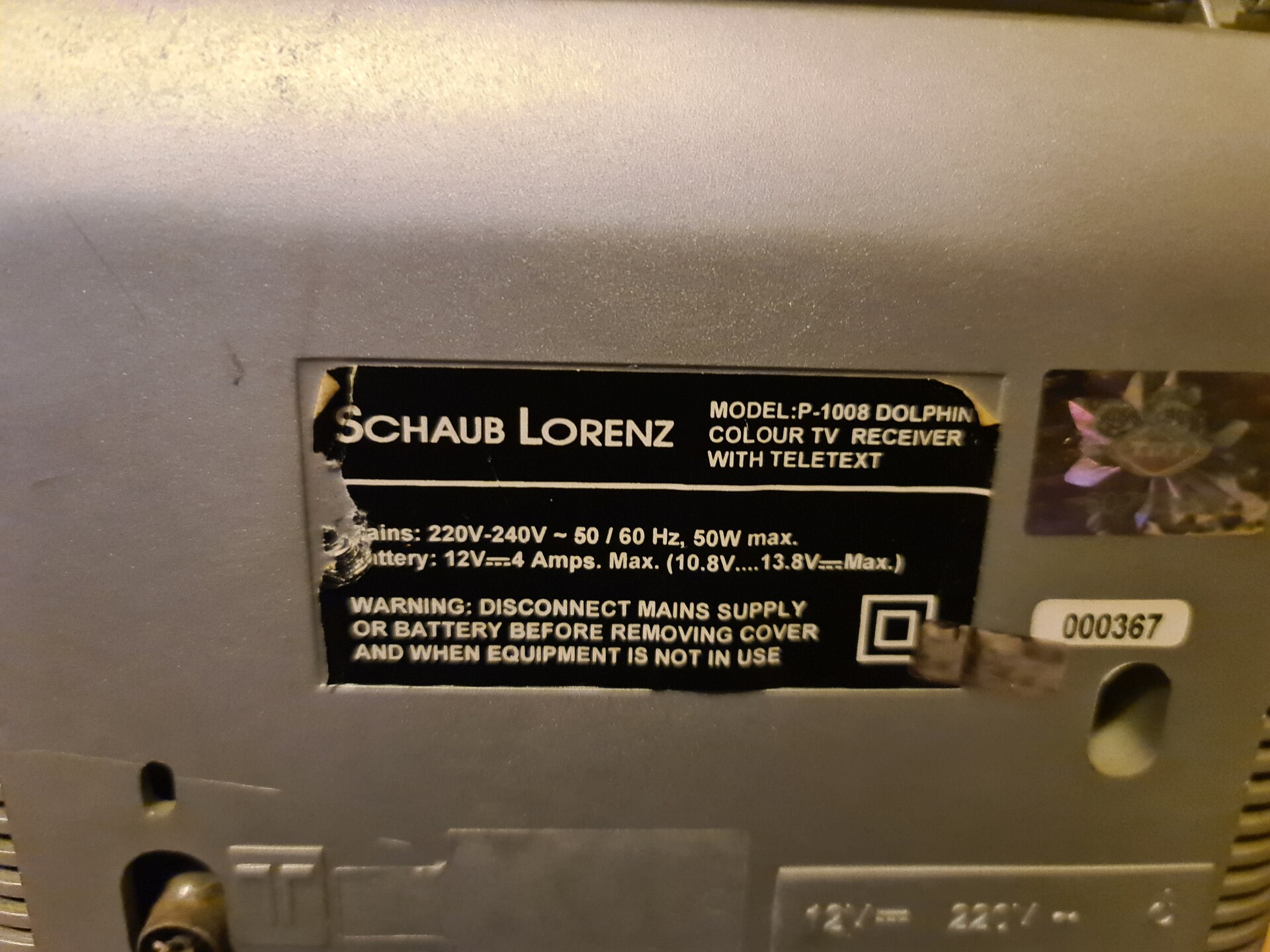
Now I had a fully functional convertion cable but I needed a TV. I checked the second-hand seller websites and found a cheap 14" CRT TV. The brand was the same, but the product model was different than the one my relative had. 


Look at the production date, it's May 2005! Which is very late for this kind of TVs I suppose!

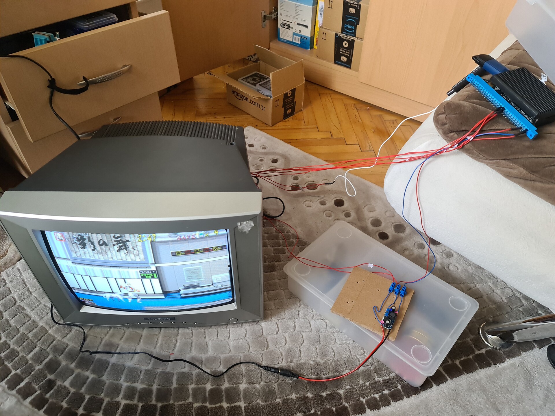
4. Tests and Final Preparations

I tested the TV with my Jamma to Scart cable, and it even works with the original Neo-Geo MVS arcade board!

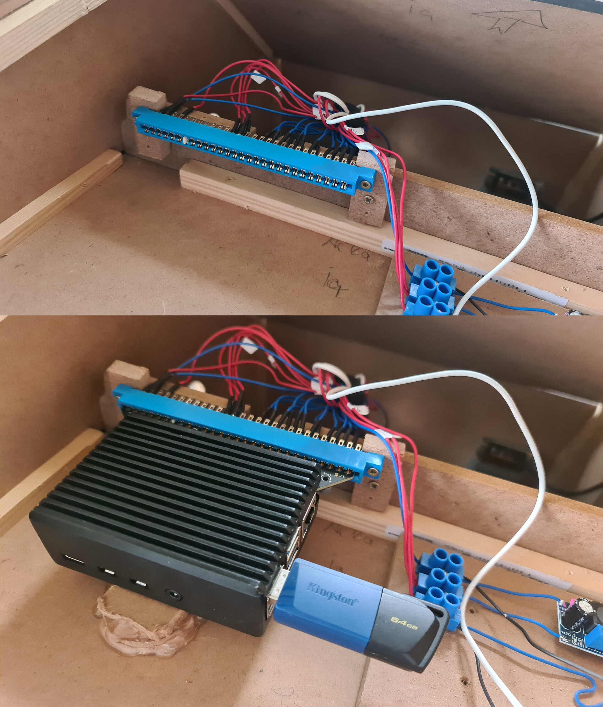
Meanwhile I bought an aluminum case for the Raspberry Pi 4 1GB version to work as a cooling system. I don't like fans, since it's not exceeding 55 °C with this case, I prefer using it like that.


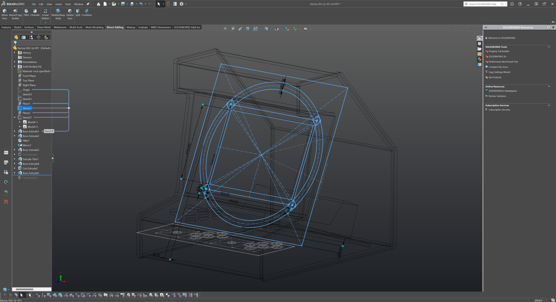
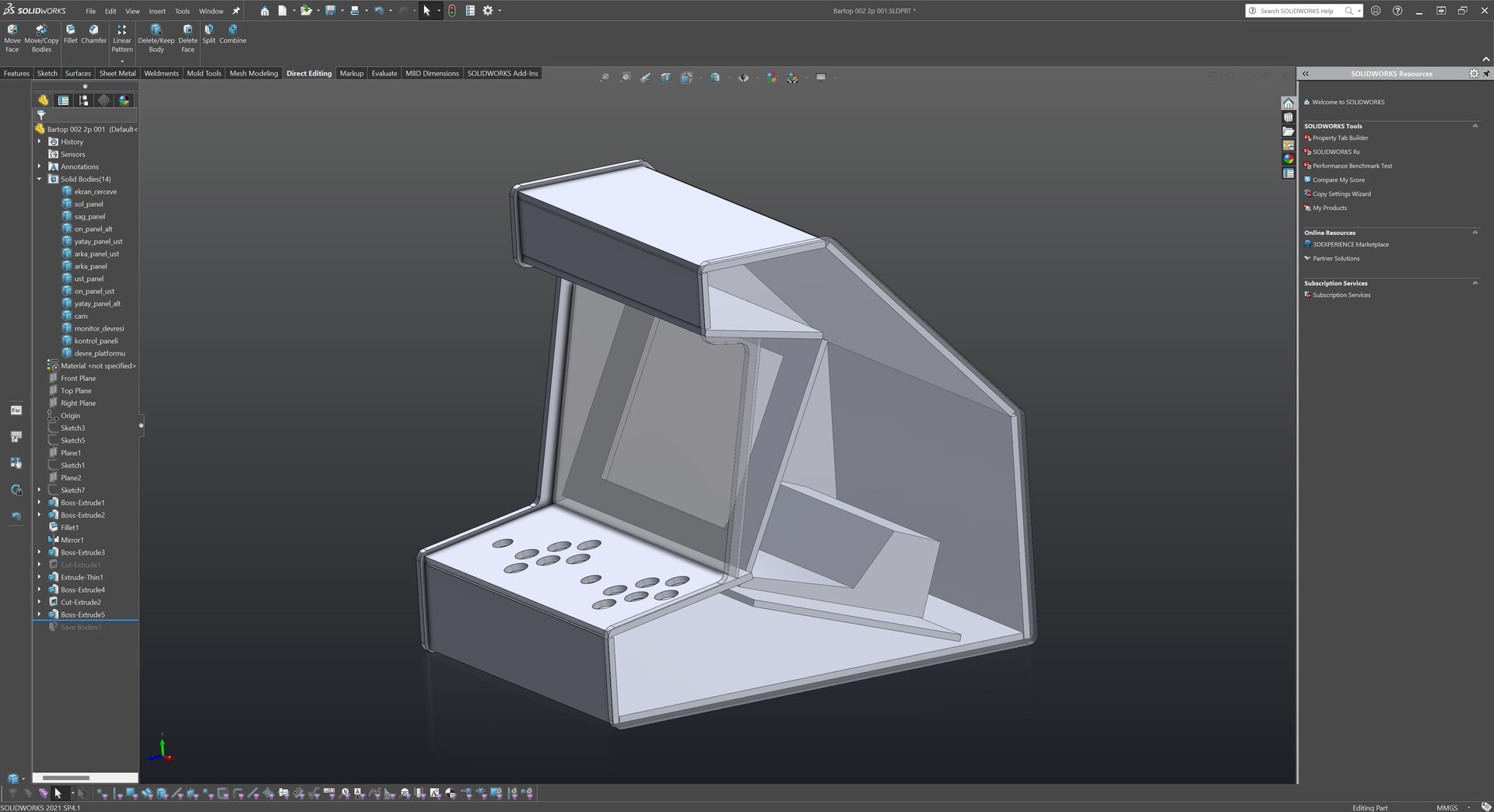
4. Designing the Cabinet

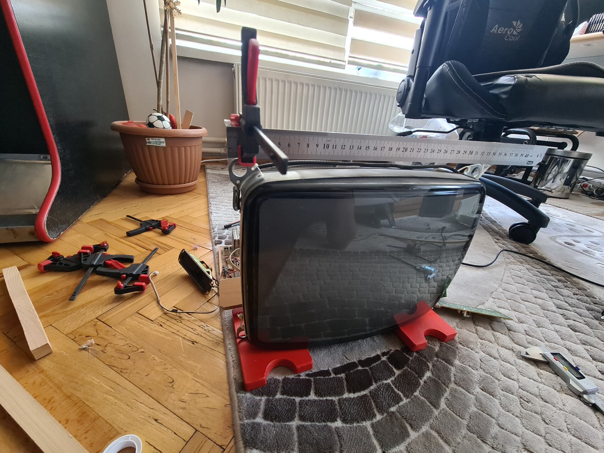
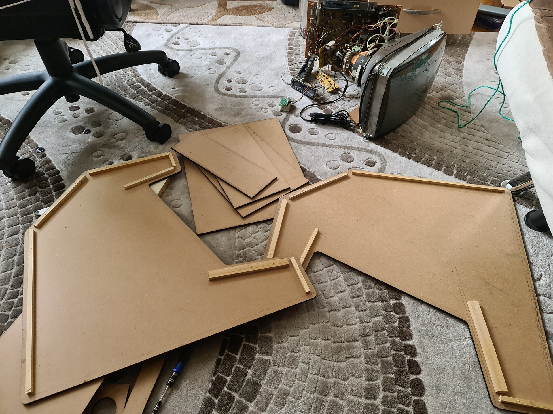
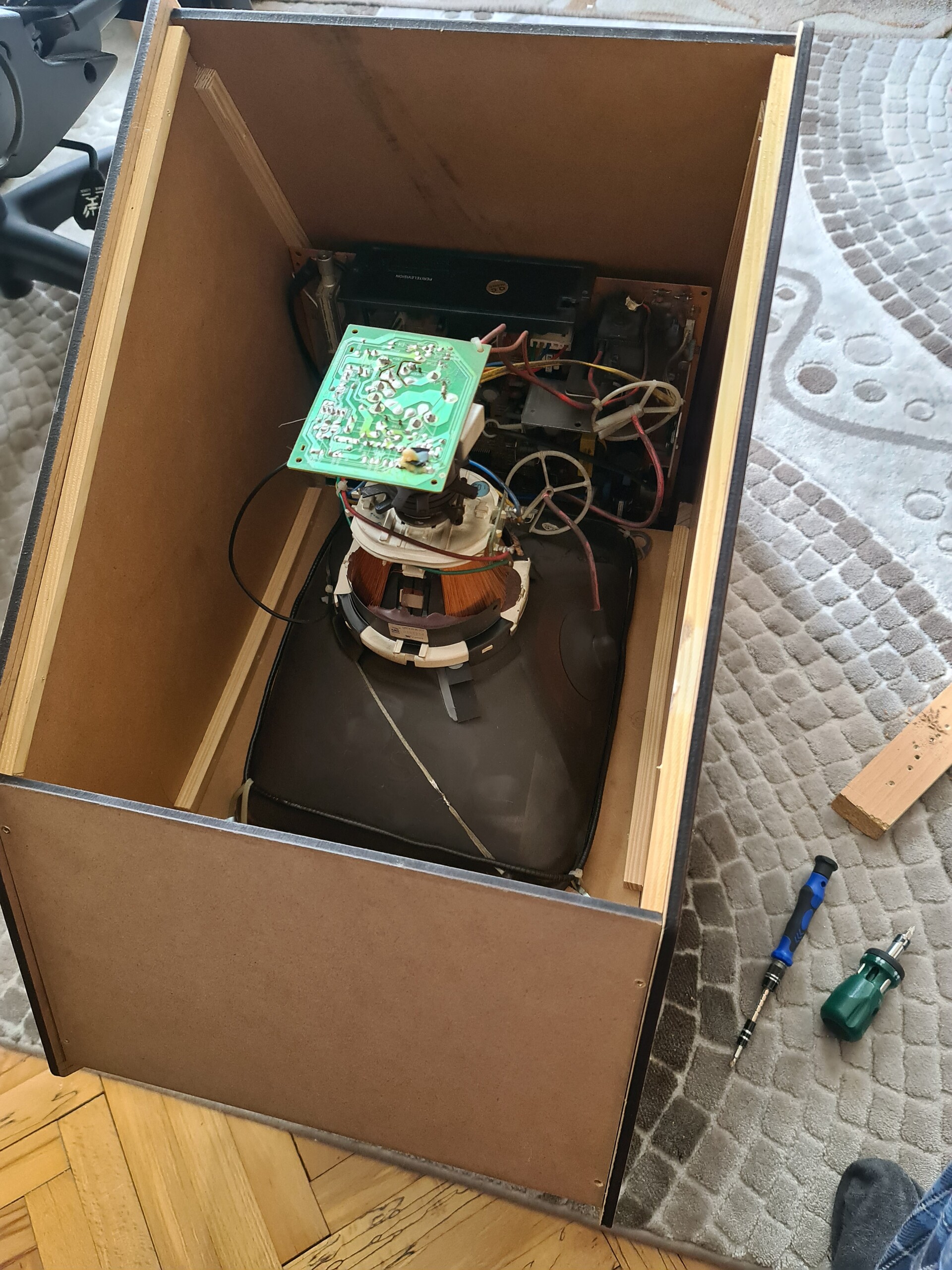
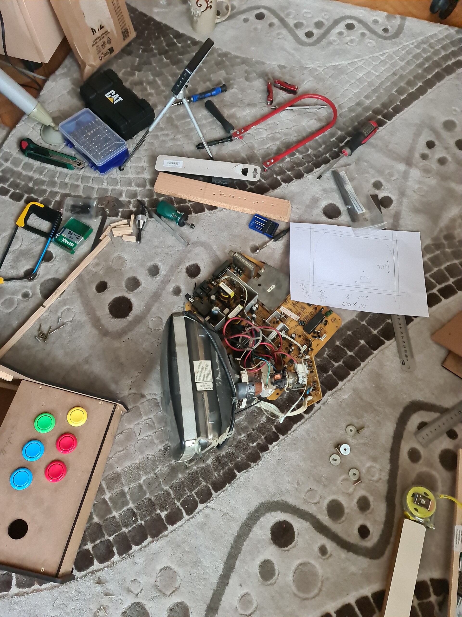
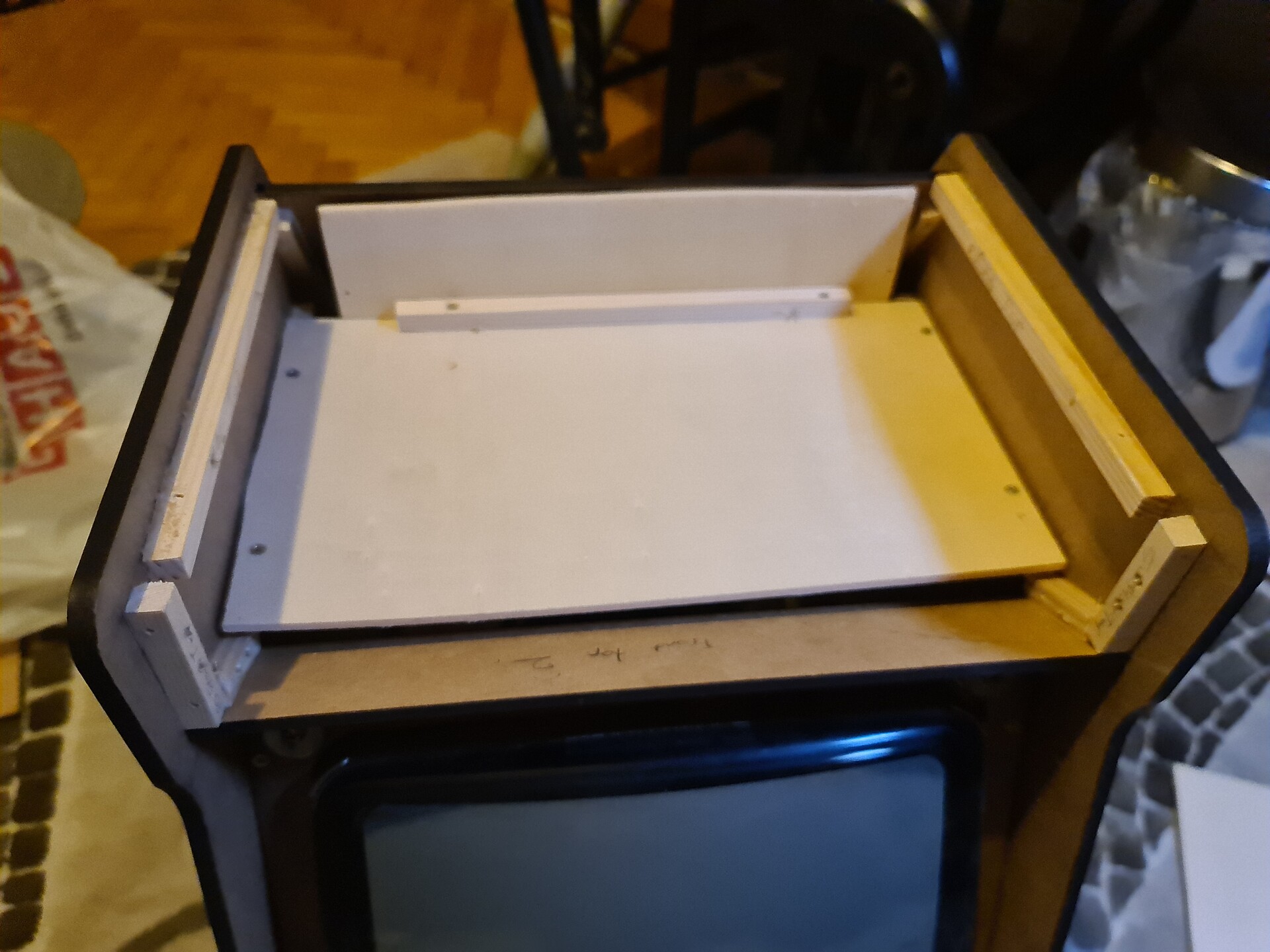
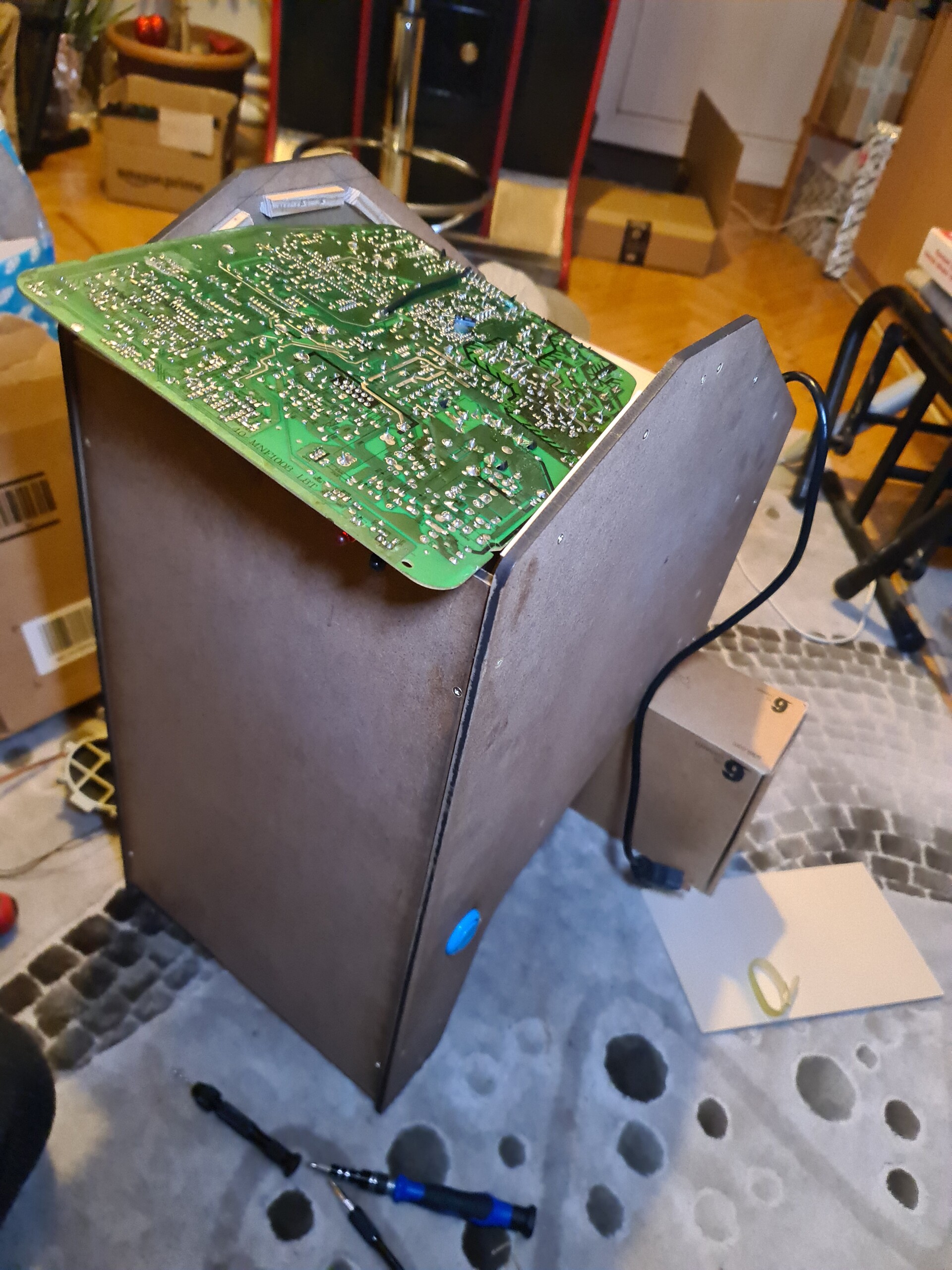
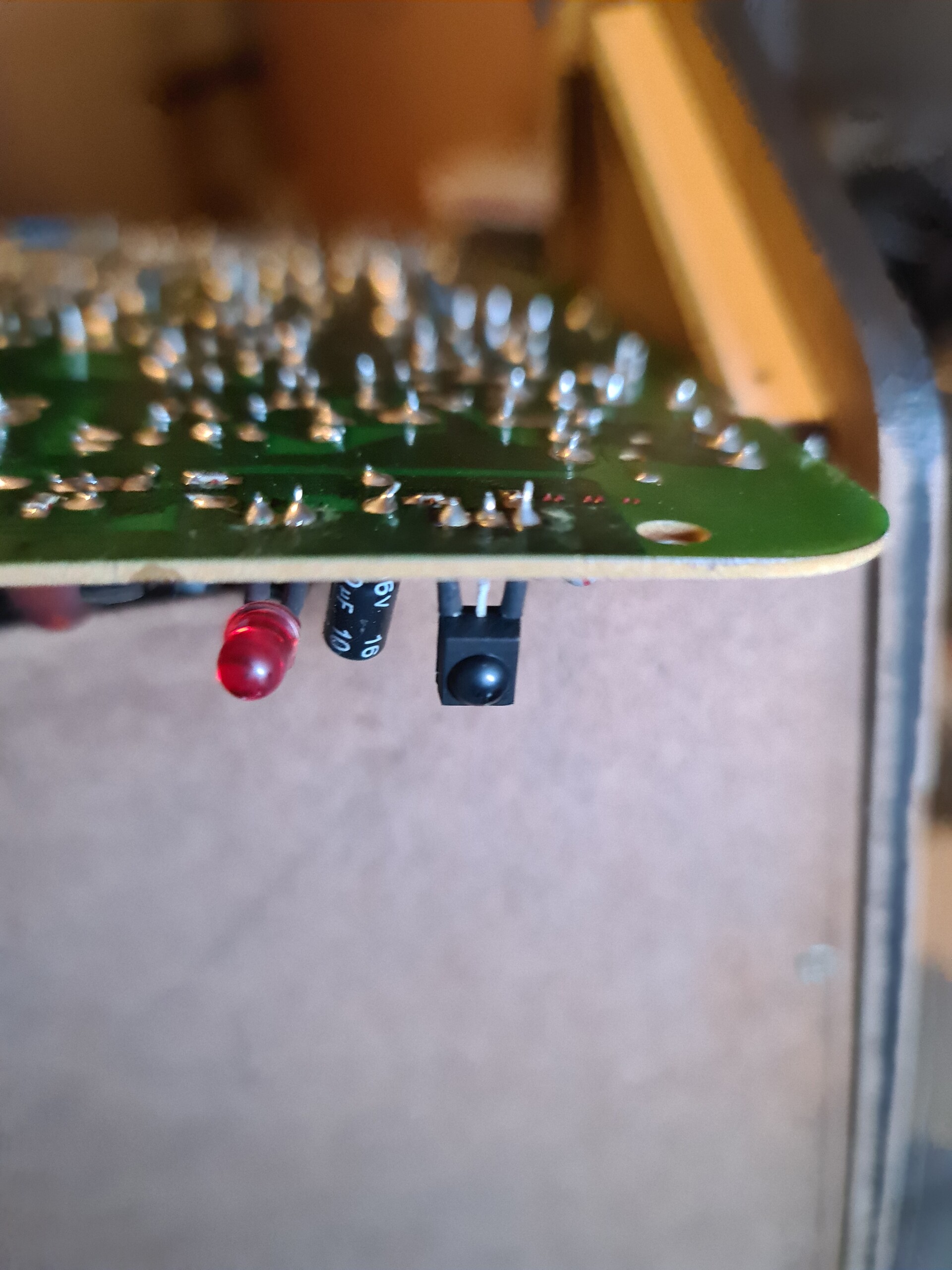
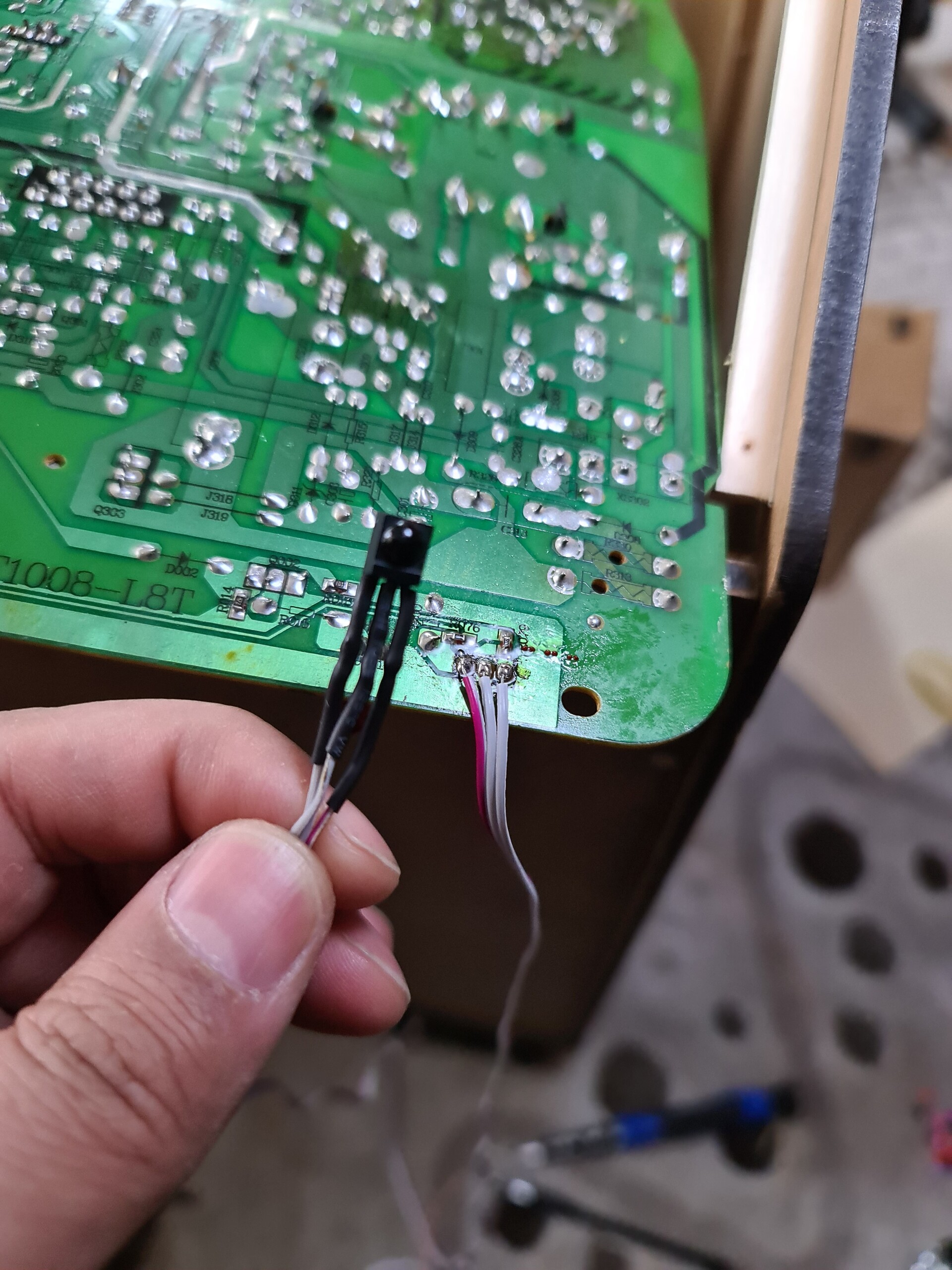
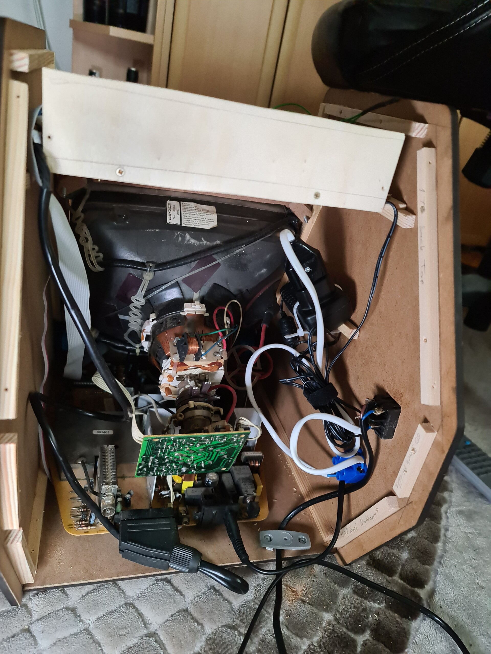
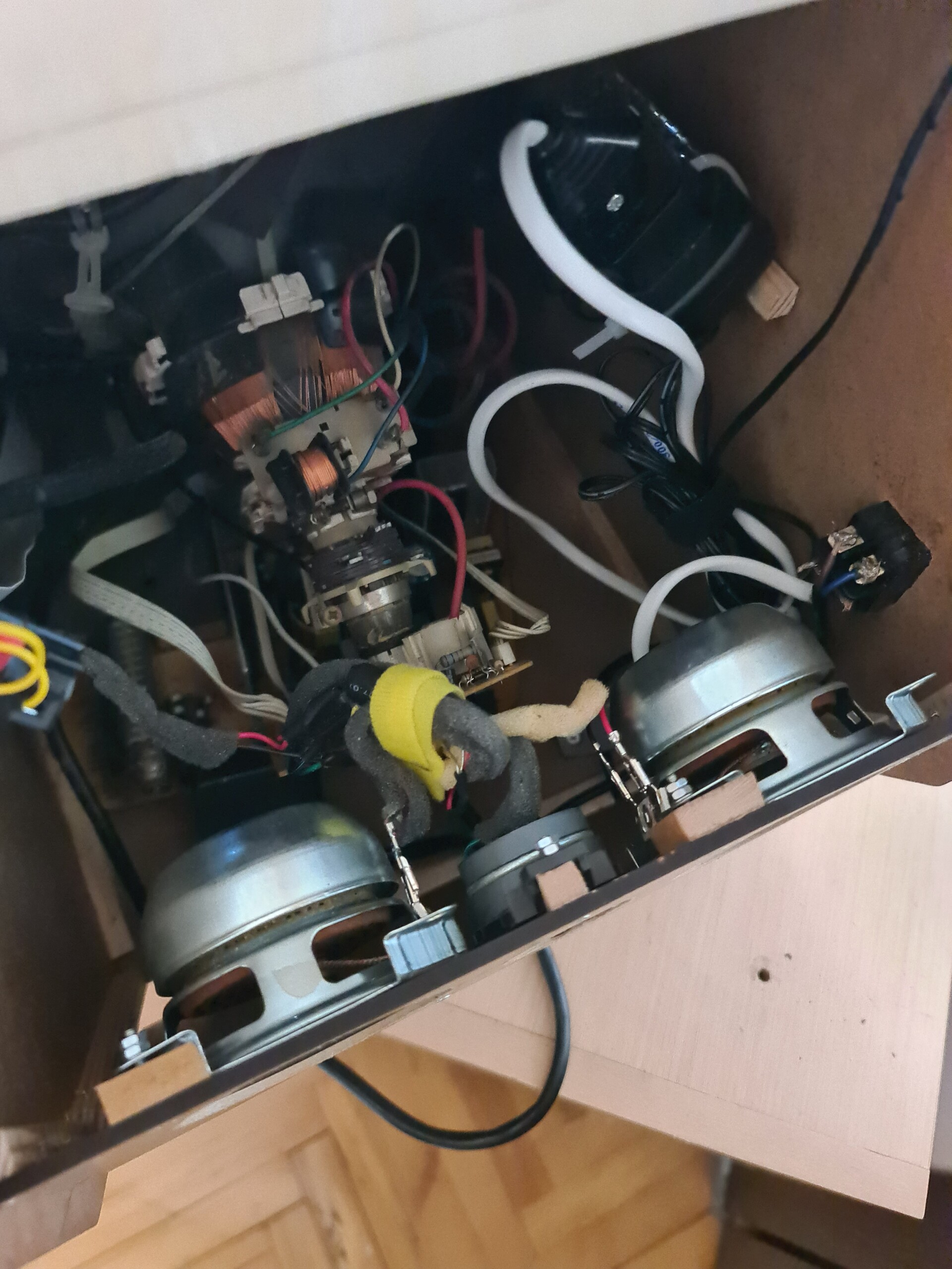
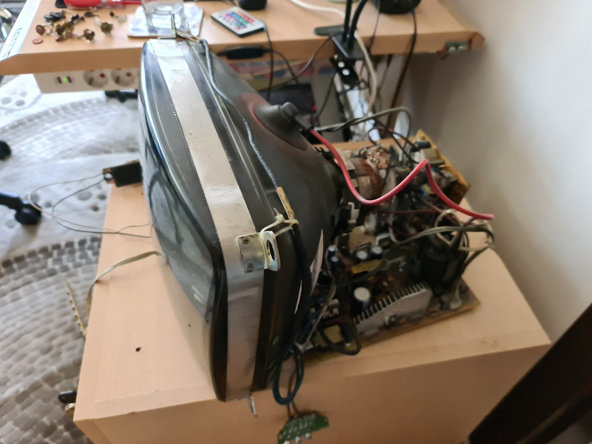
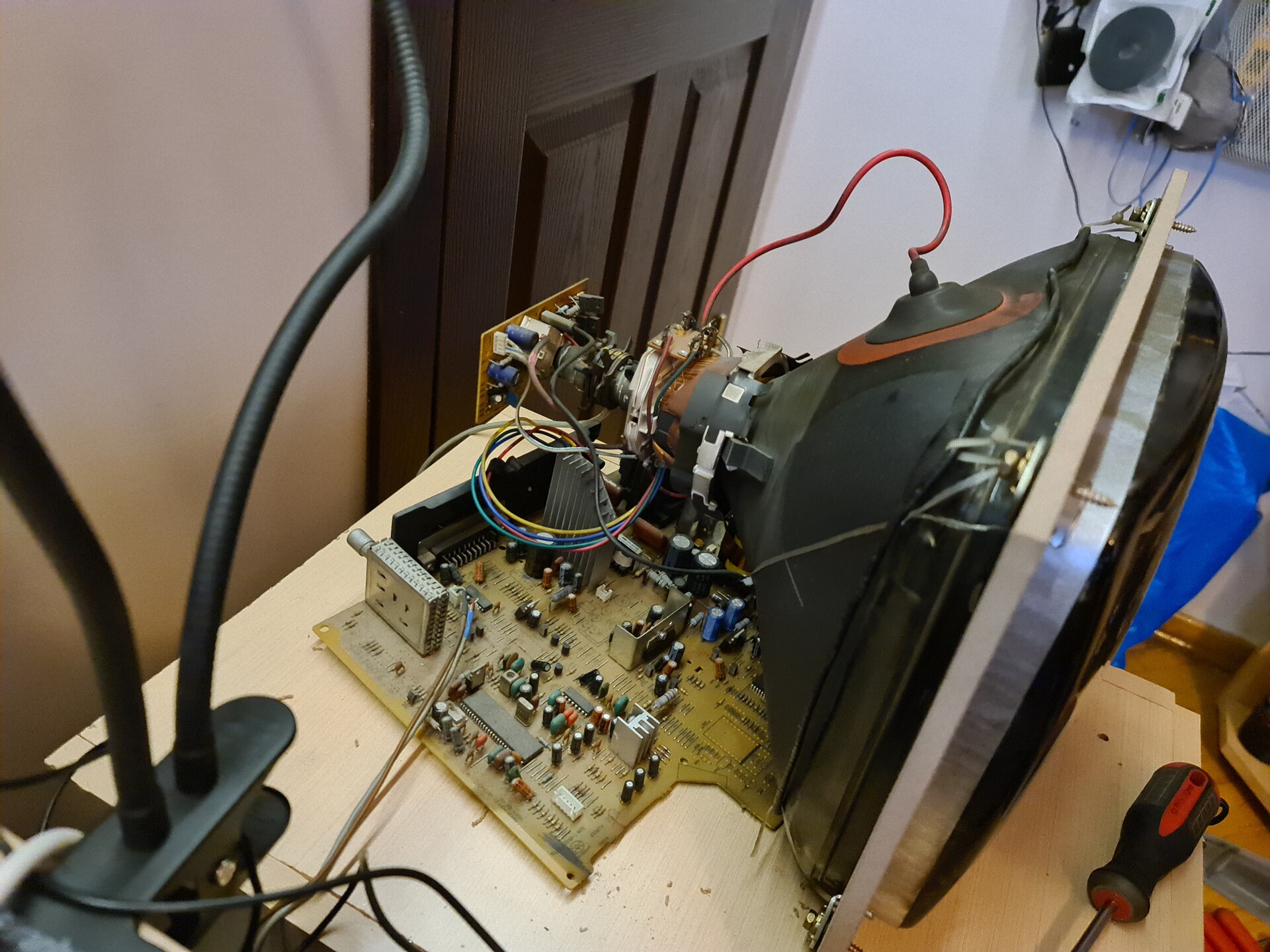
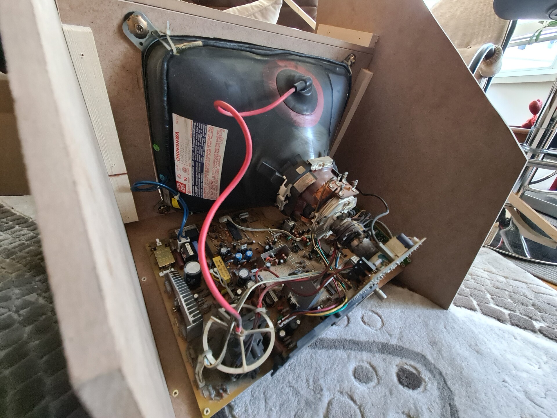
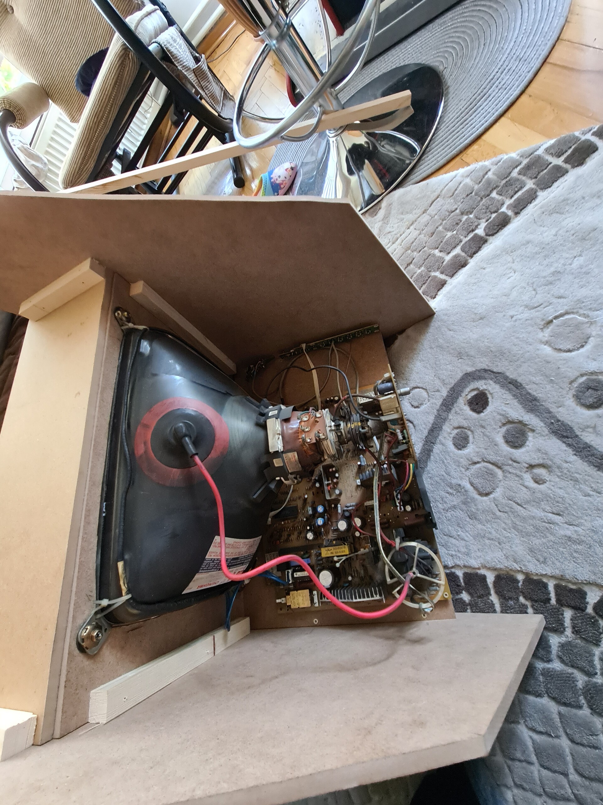
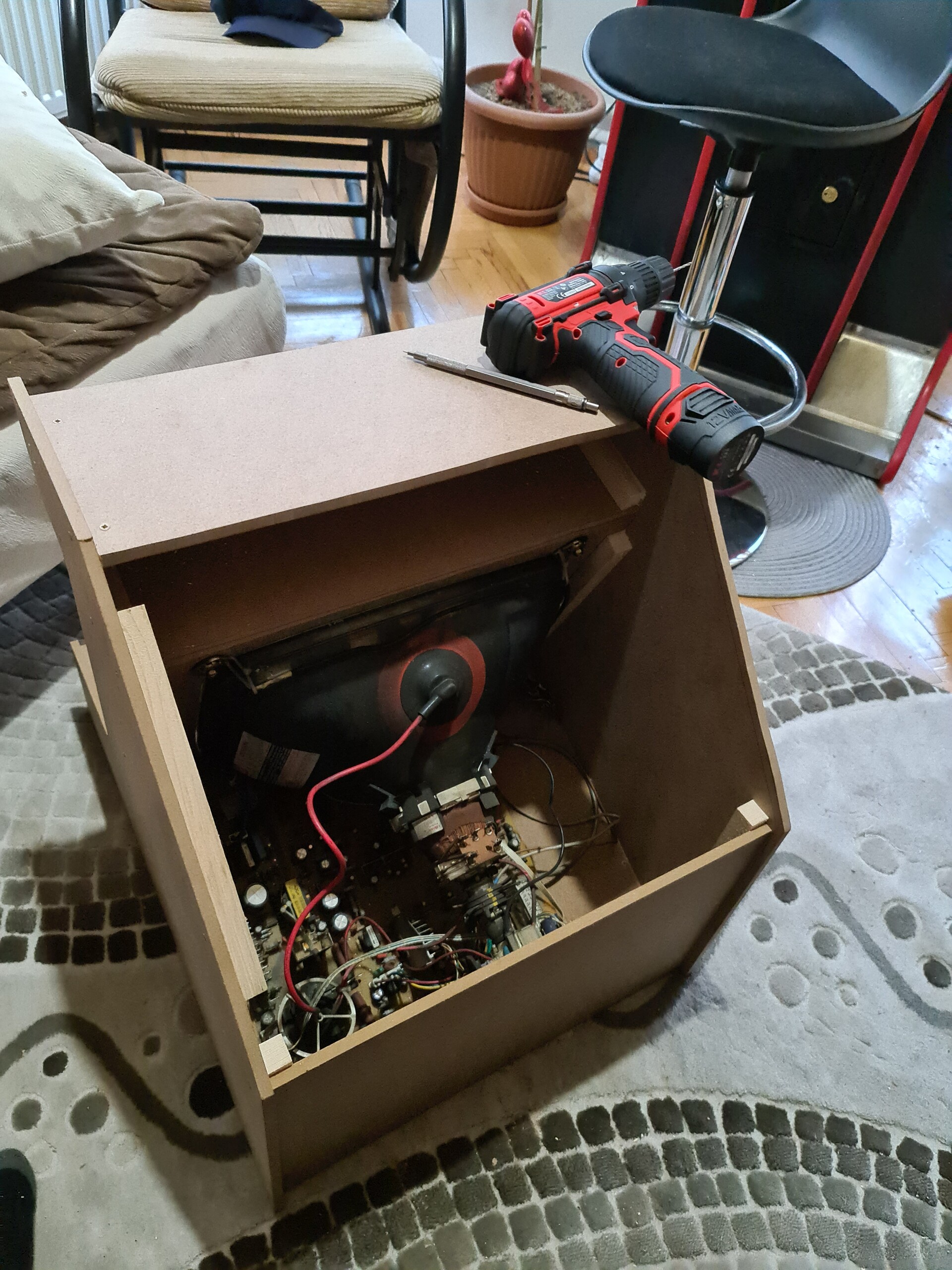
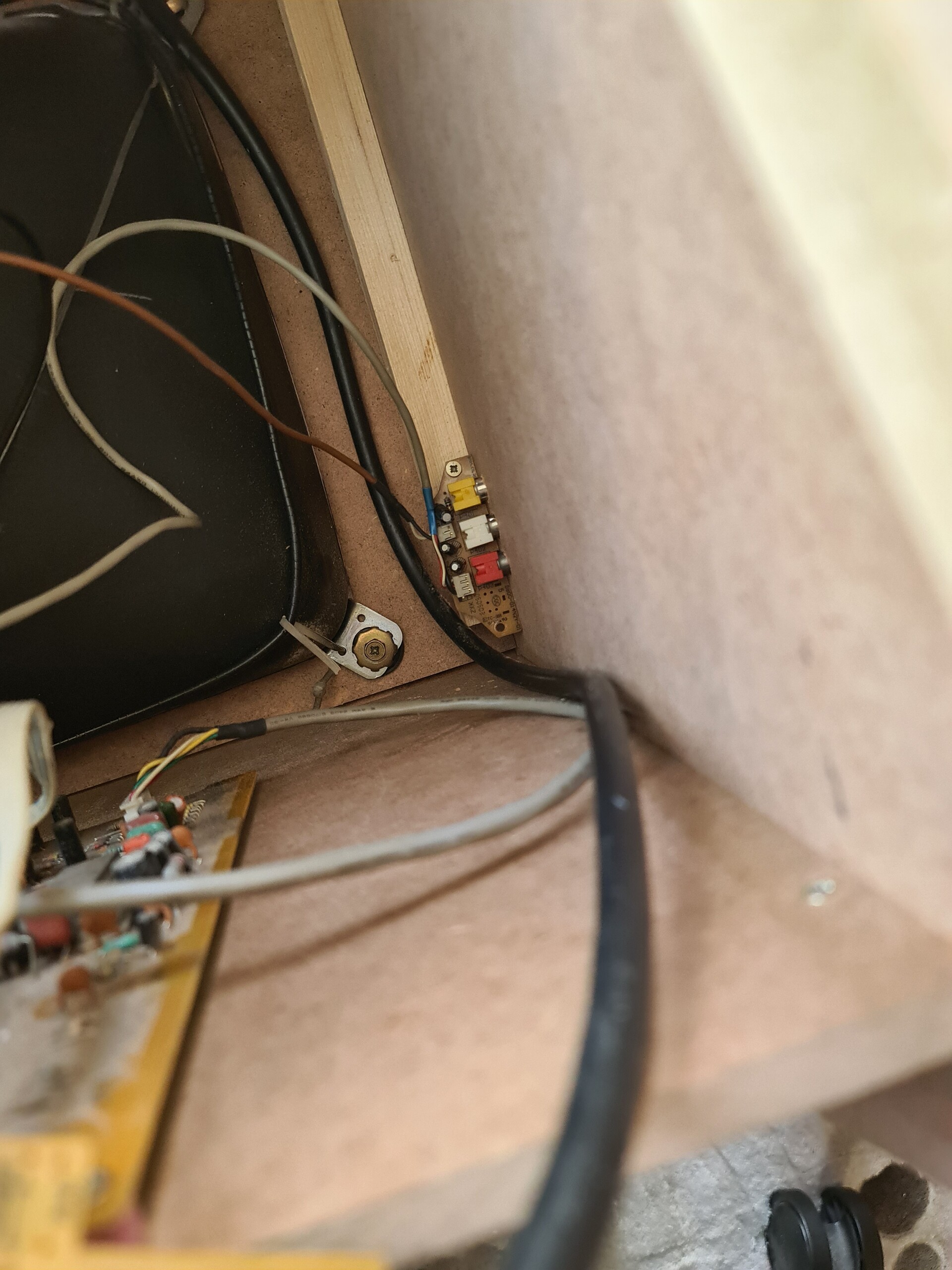
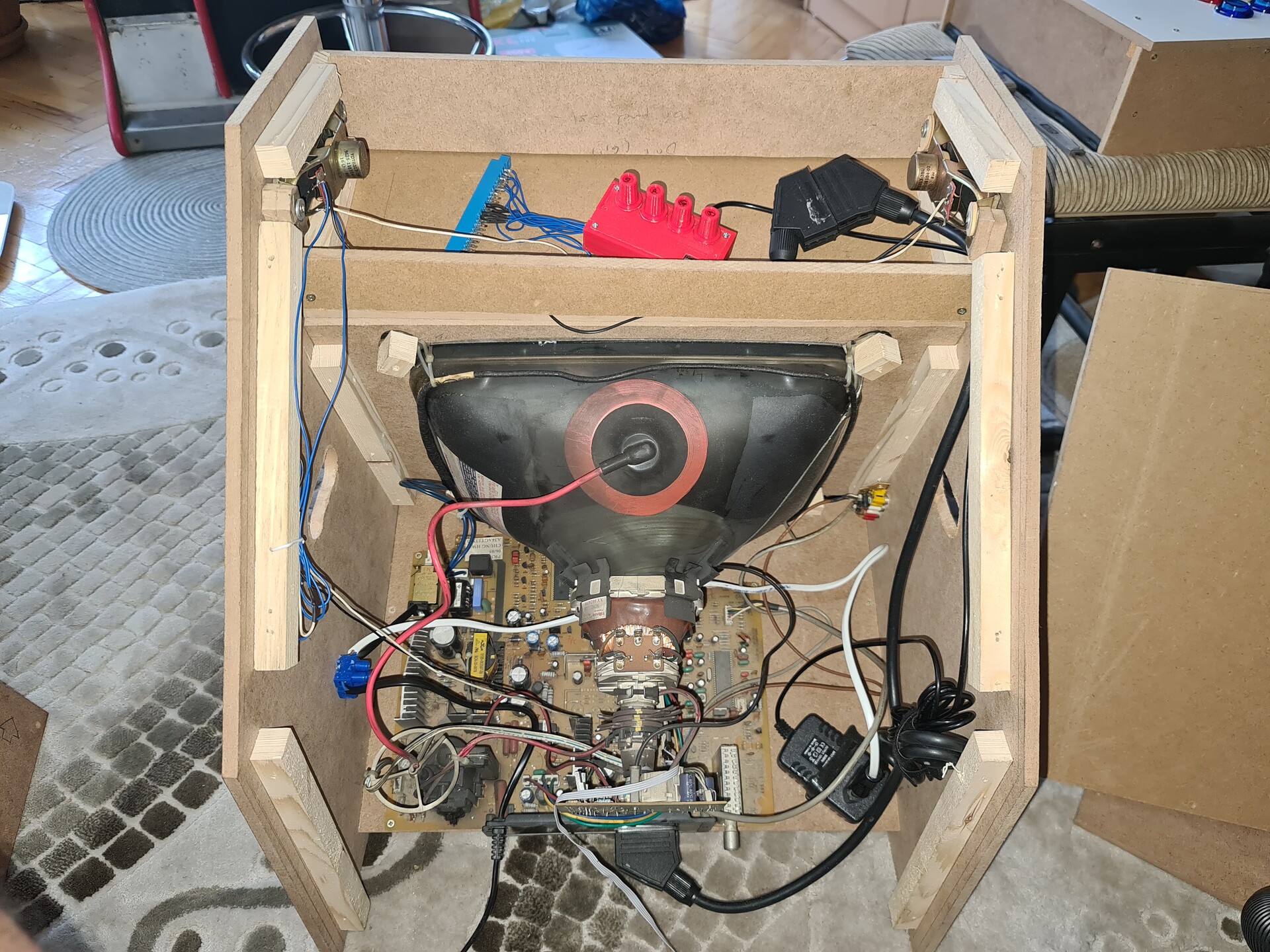
As a starter, I disassembled the case of the CRT TV and took measurements to fix it to the new case I'm going to design.

I measured the board of the TV as well. By the way, there is 20000 volts inside that tube. Normally you need to discharge it, I thought I did too, but turned out to be that I didn't! Luckily I didn't realized it by getting shocked but I it with my multimeter's NCV feature. You point the multimeter to an area and it checks that there is a high voltage there or not. So there was... Luckily I didn't touched anything while dissamblying and assemblying it :S

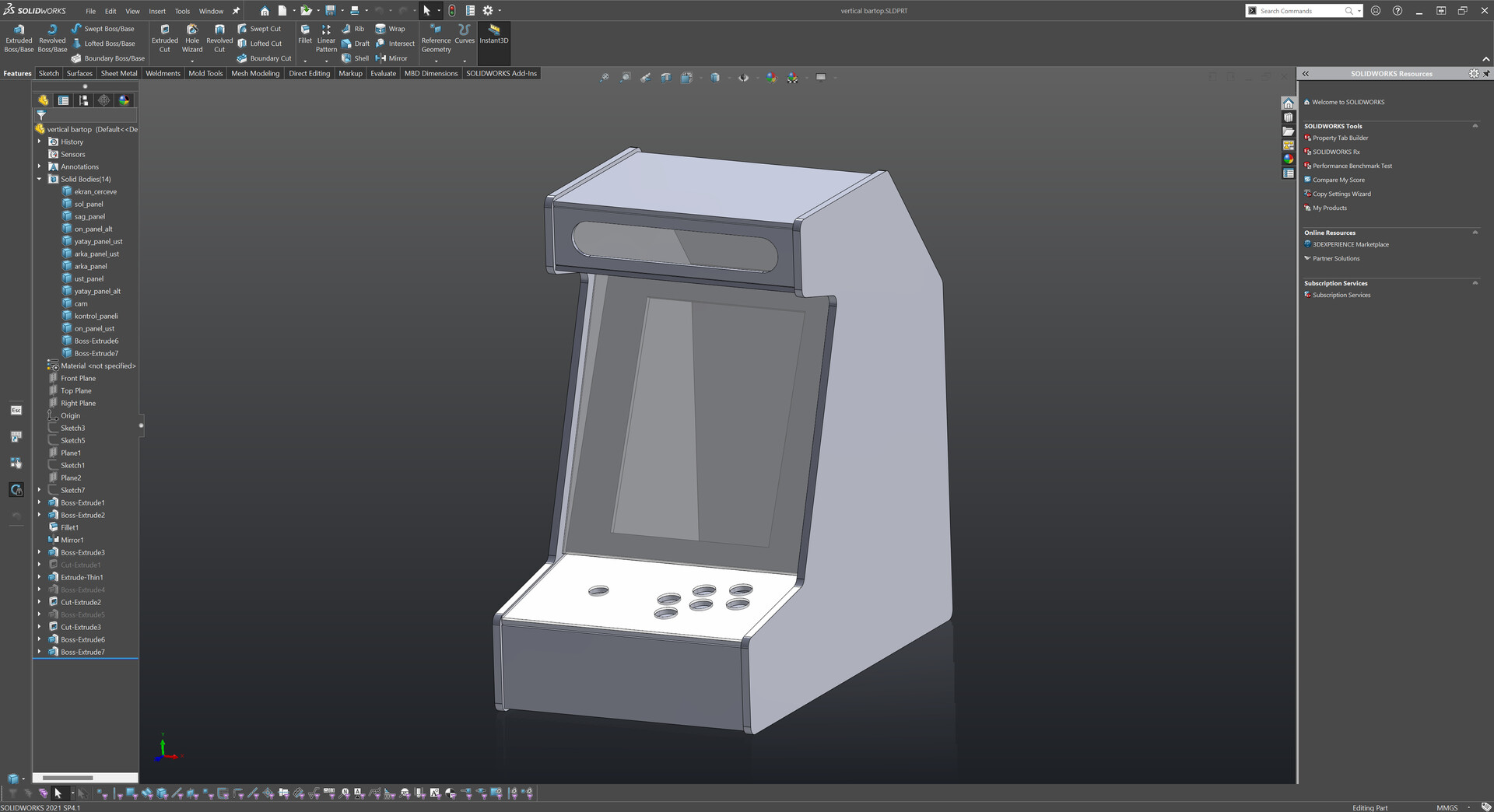
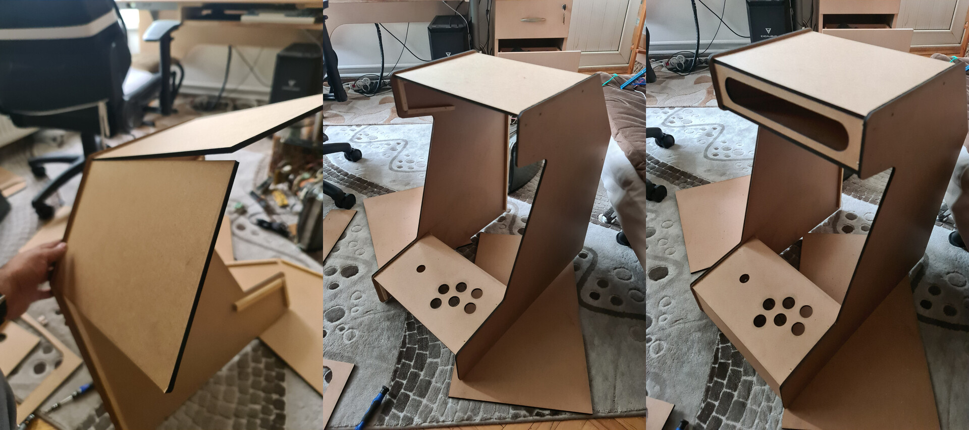
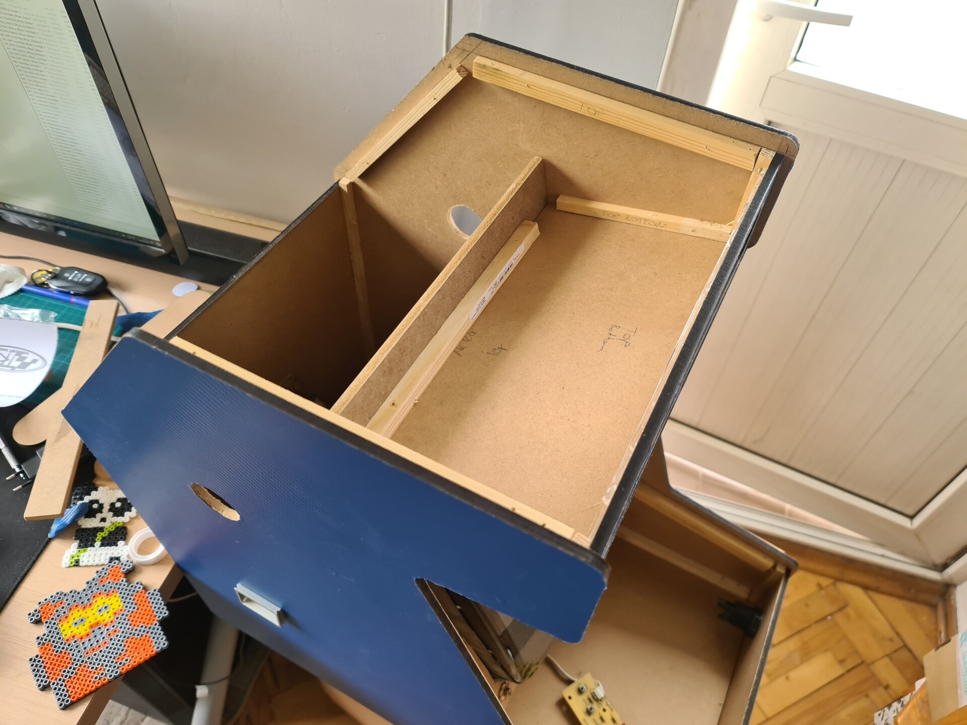
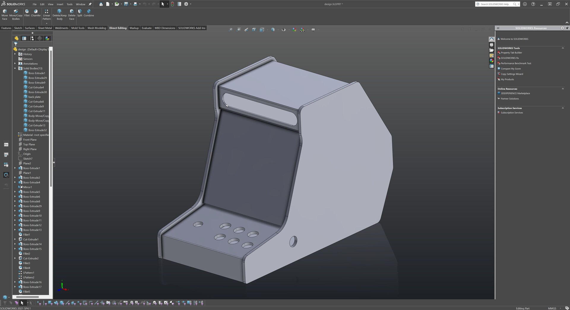
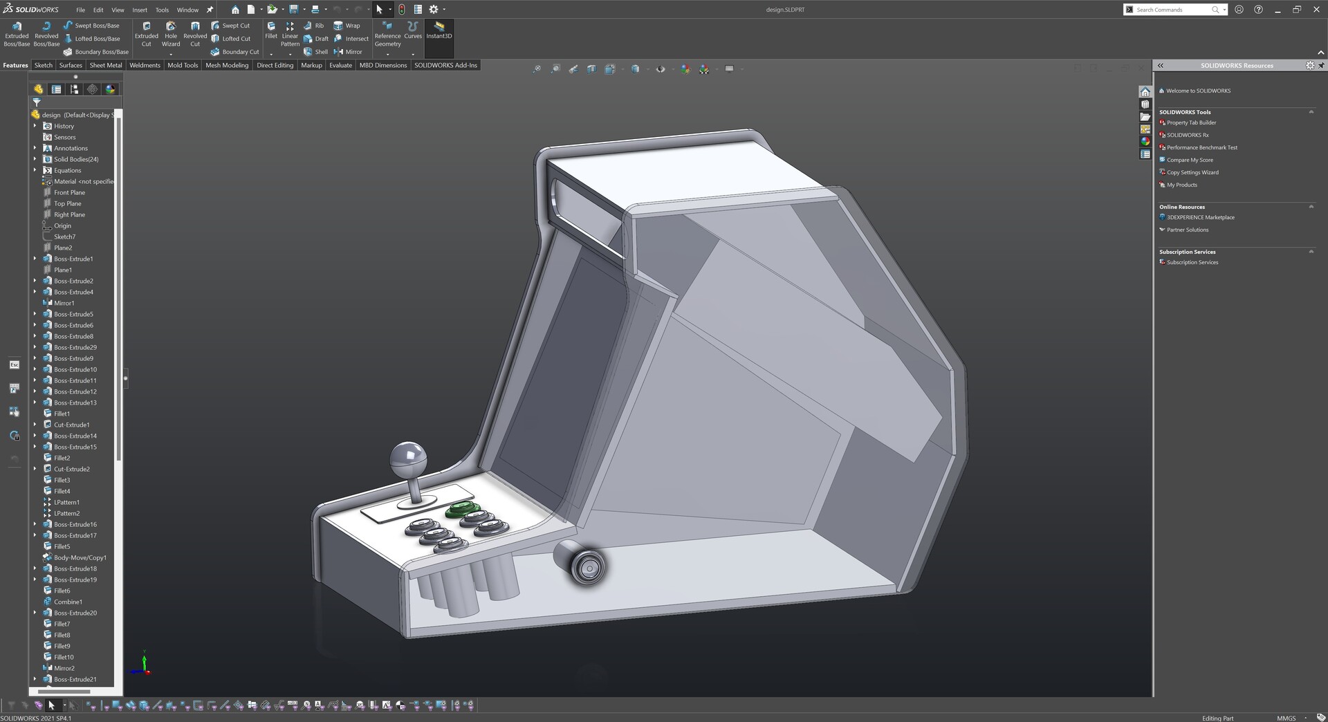
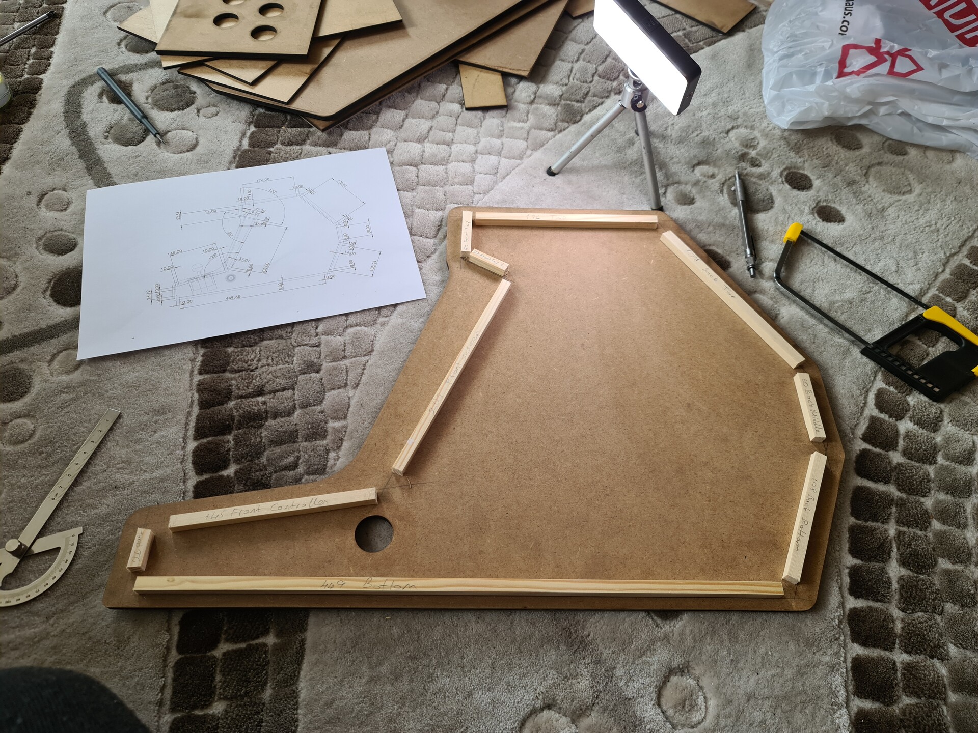
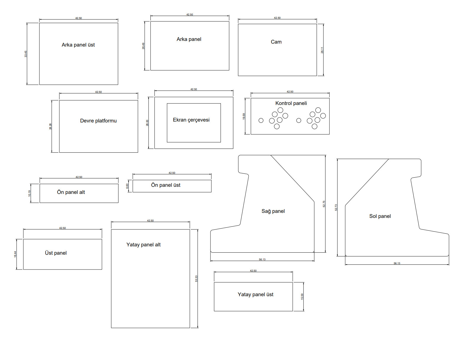
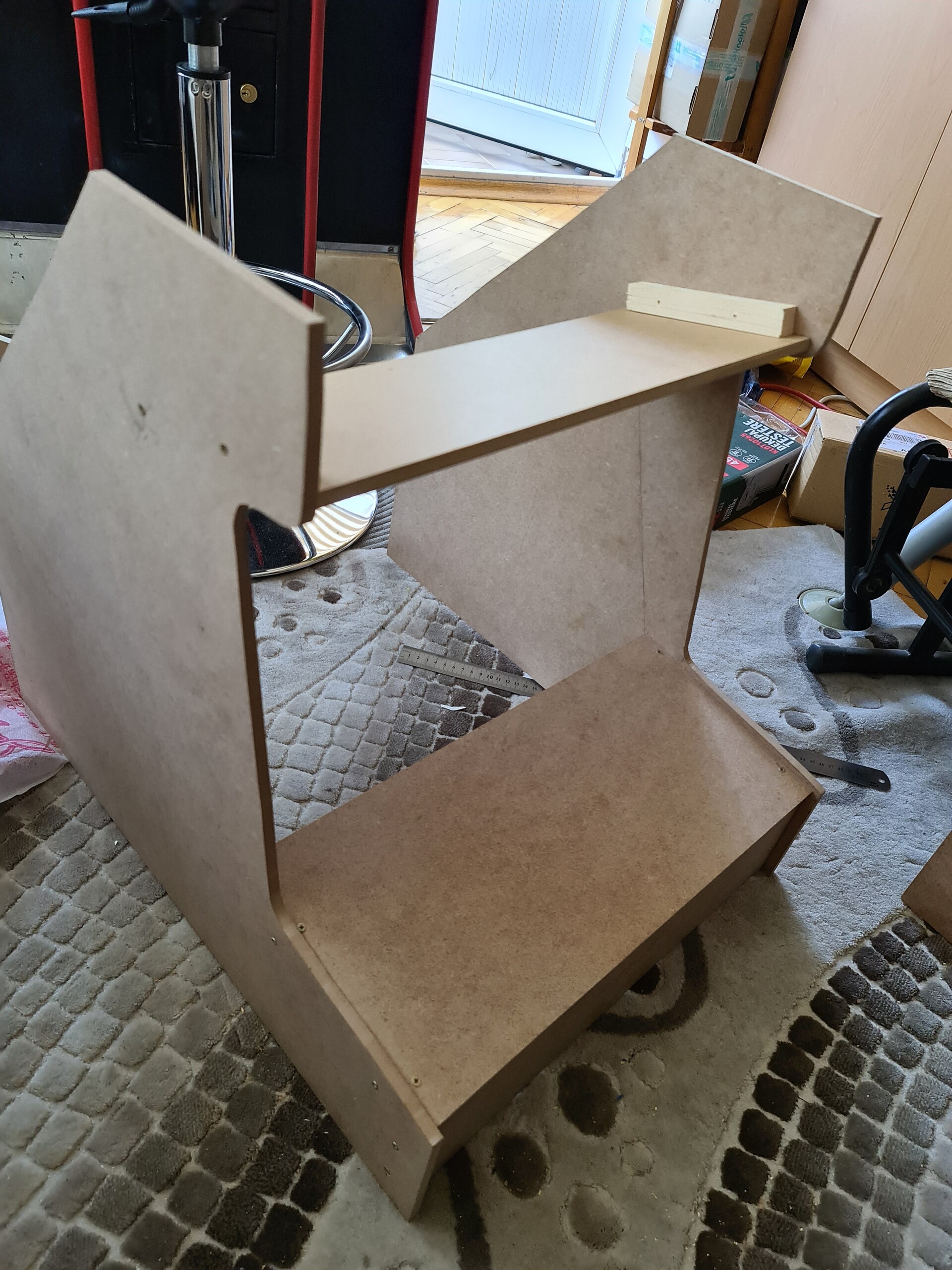
Anyway, I applied the simple measurements to my design, and defined simple boards to form my bartop design.

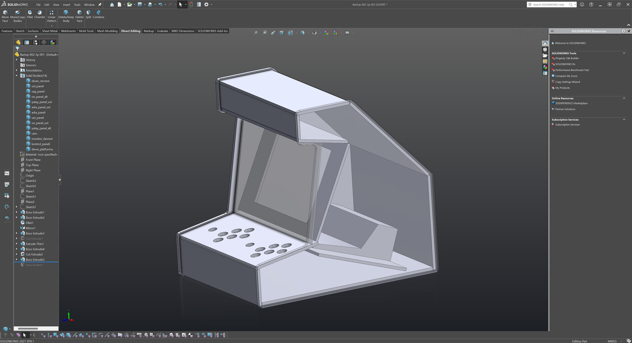
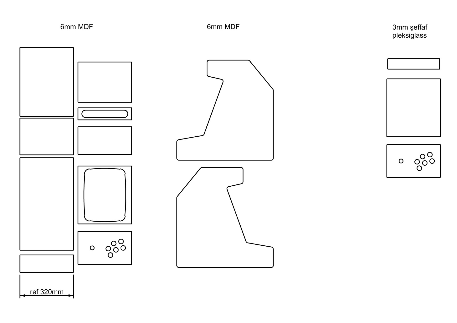
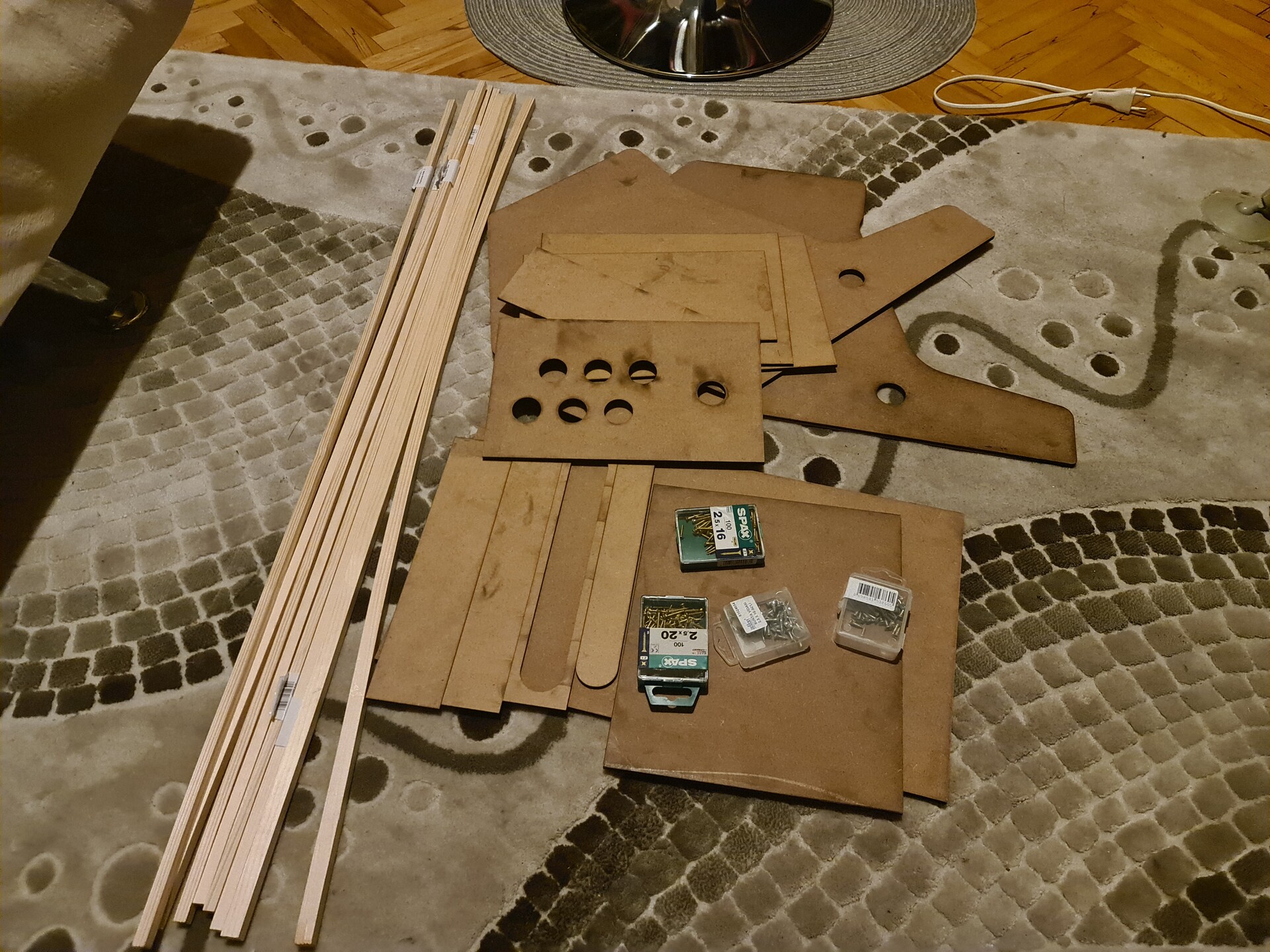
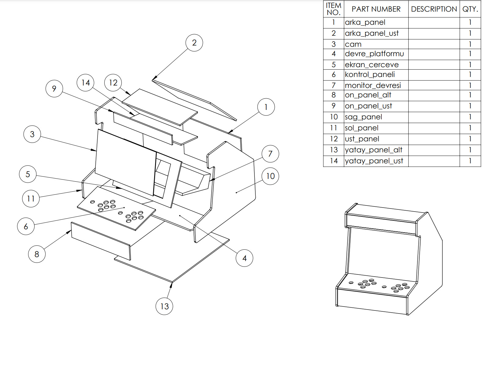
After creating the rough design, I go for the bill of materials (BOM) and created a list of panels to buy them from Bauhaus around here. 

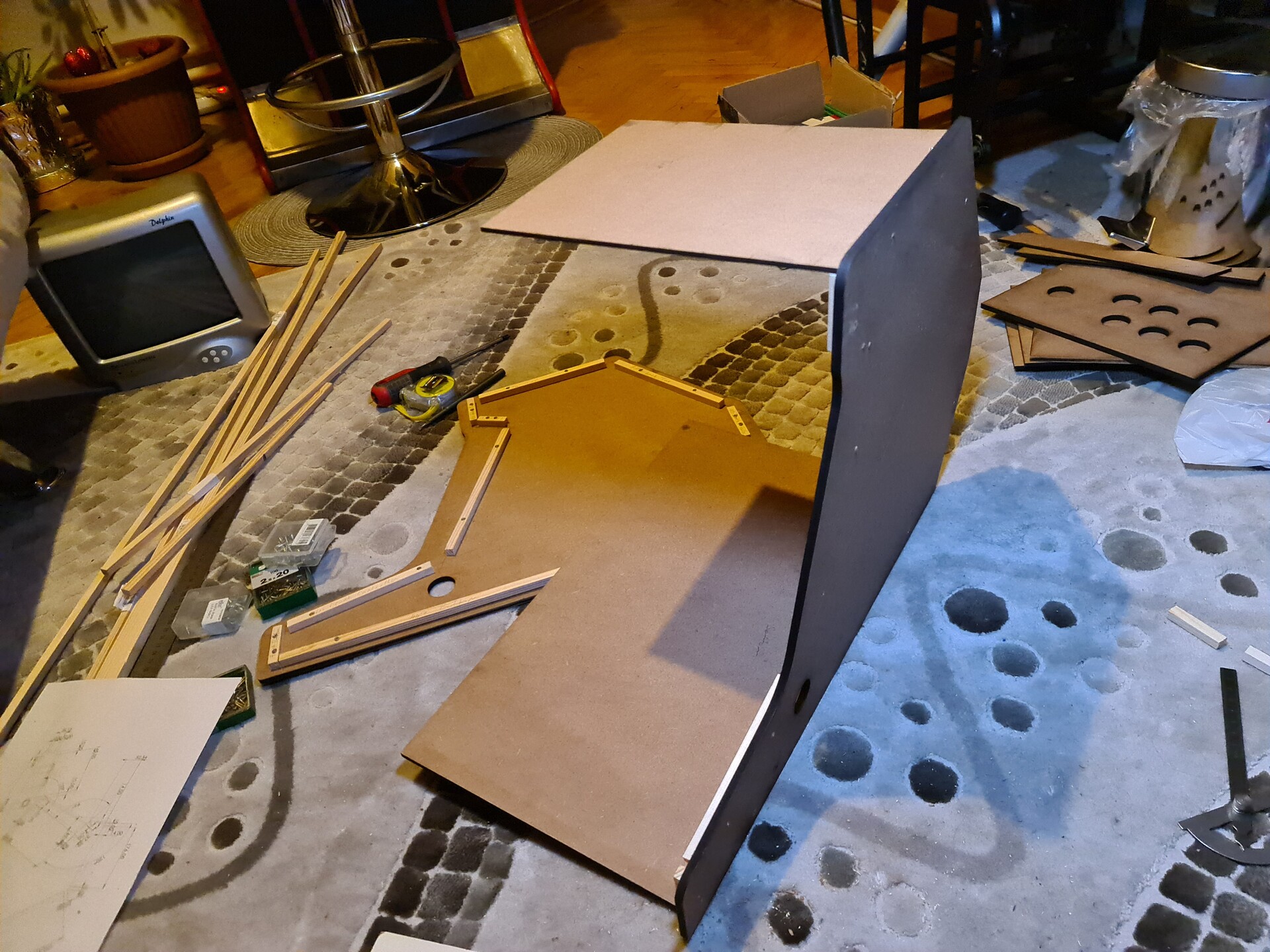
5. Constructing the Cabinet

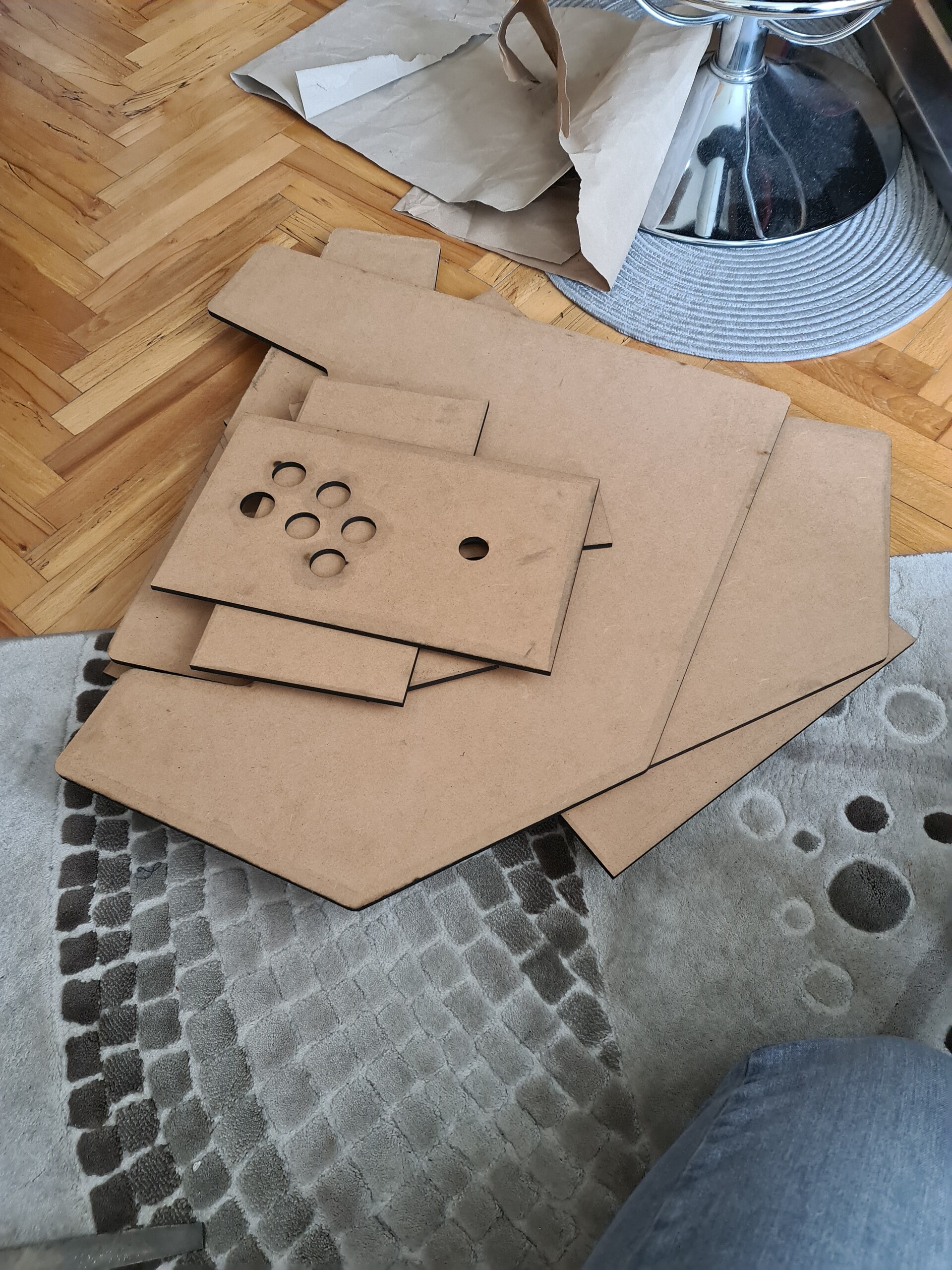
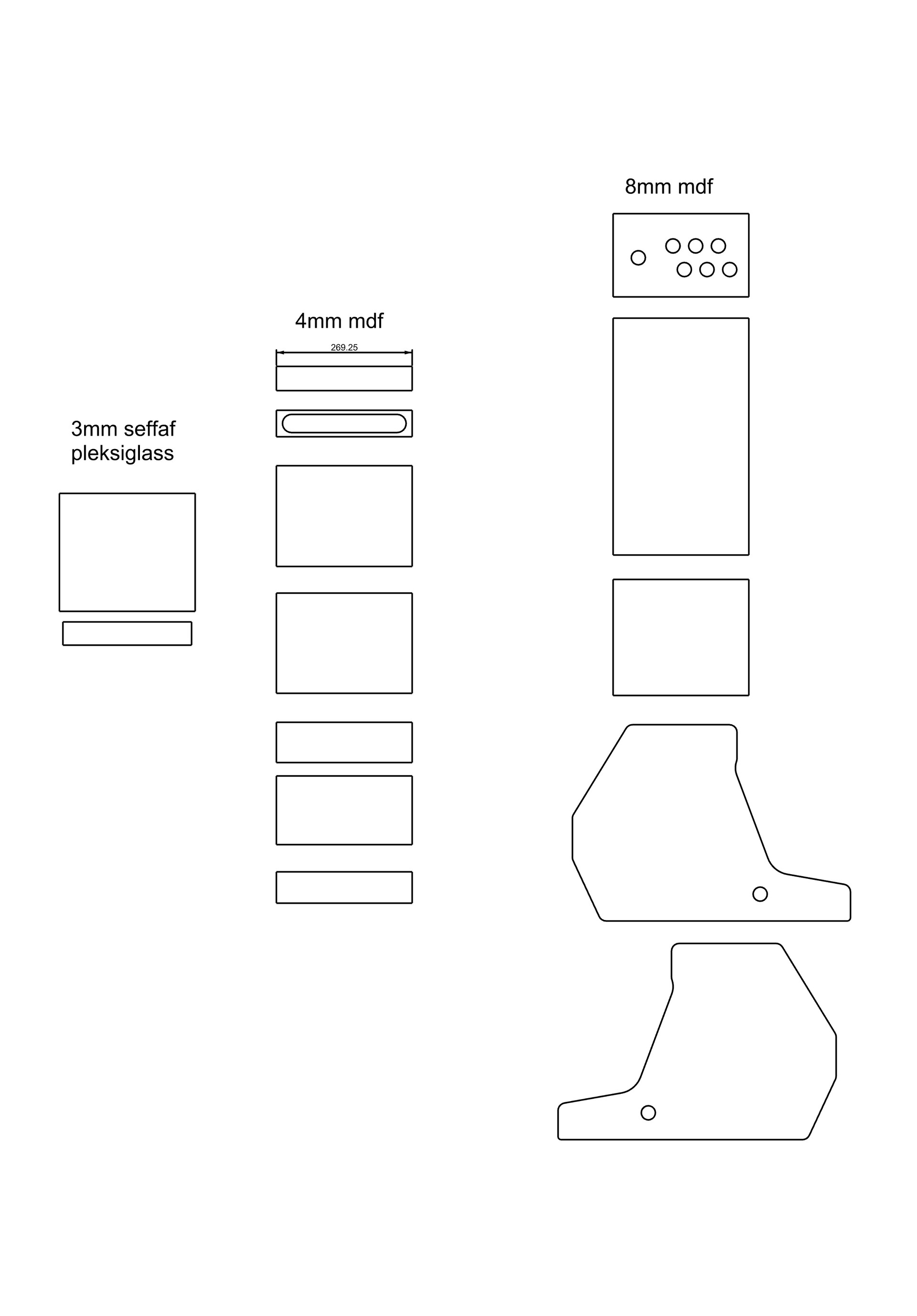
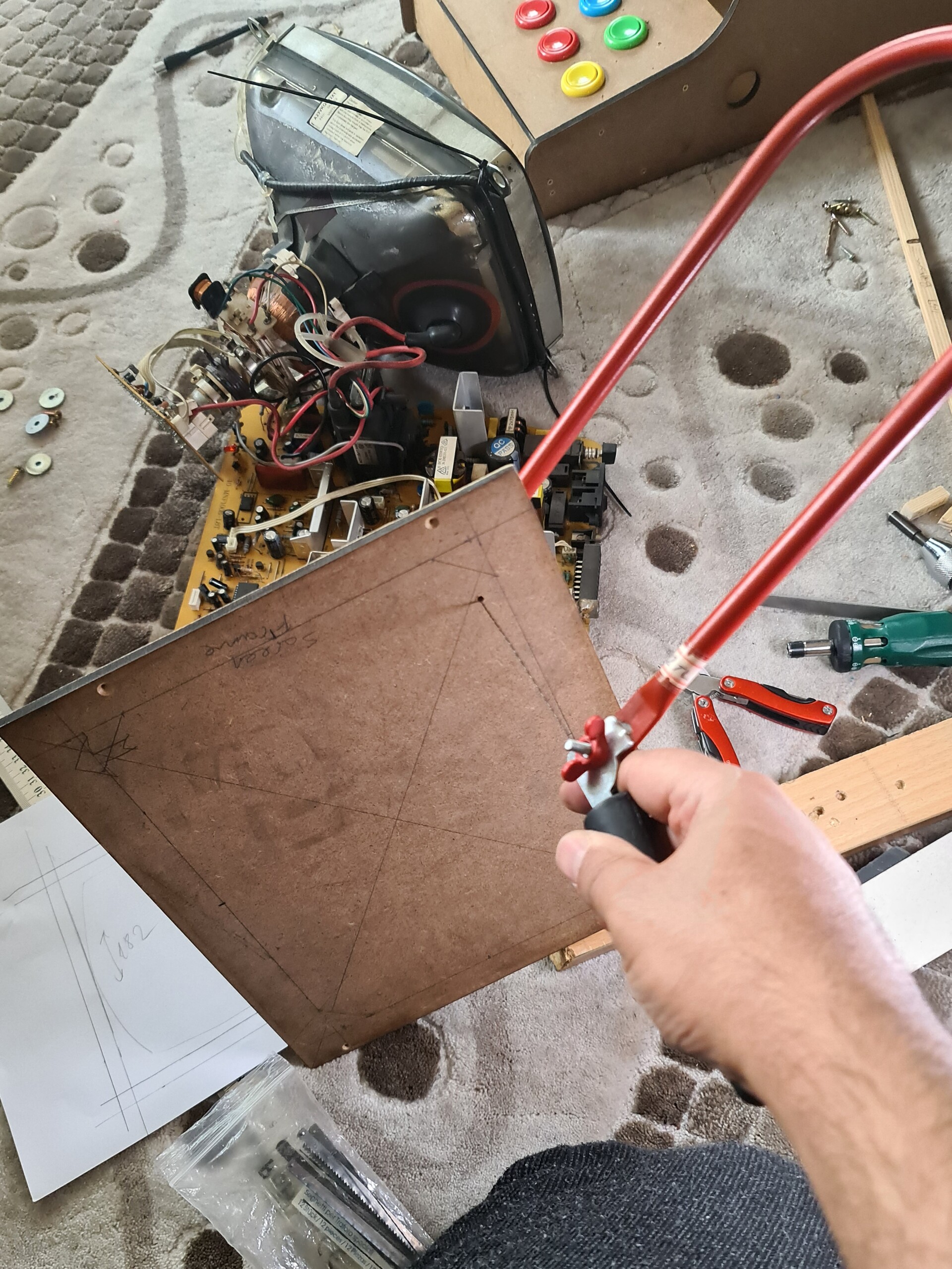
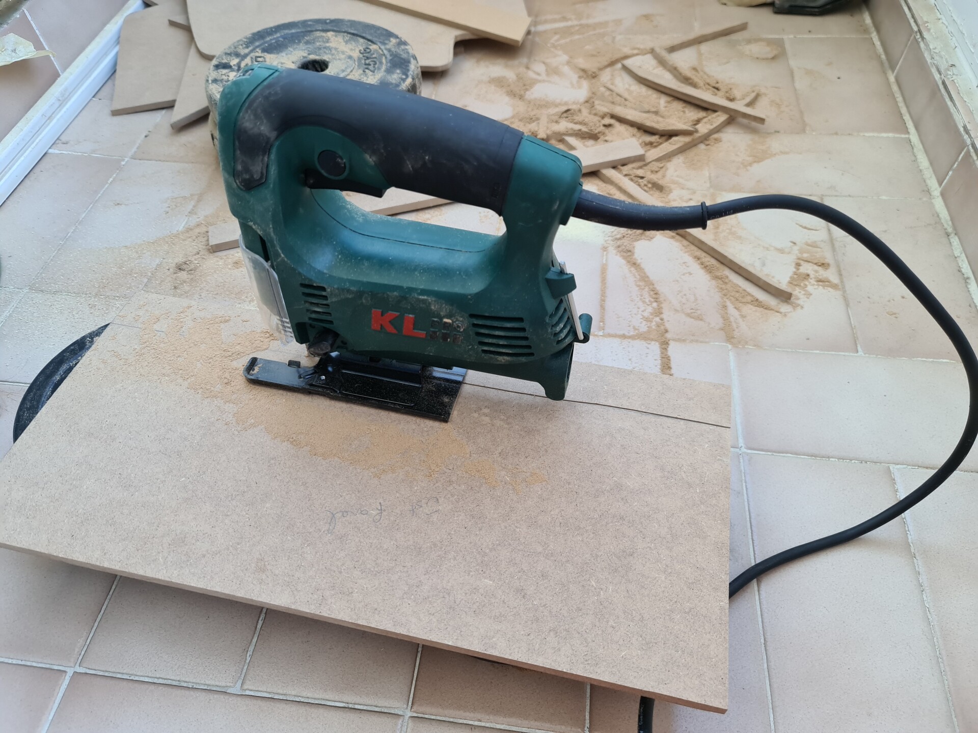
I ordered 8mm thick MDF plates as you see the dimensions right above. Bauhas can't cut these boards as their outline. They can cut only rectangle shape. So it was my job to cut these angular shapes by myself. 

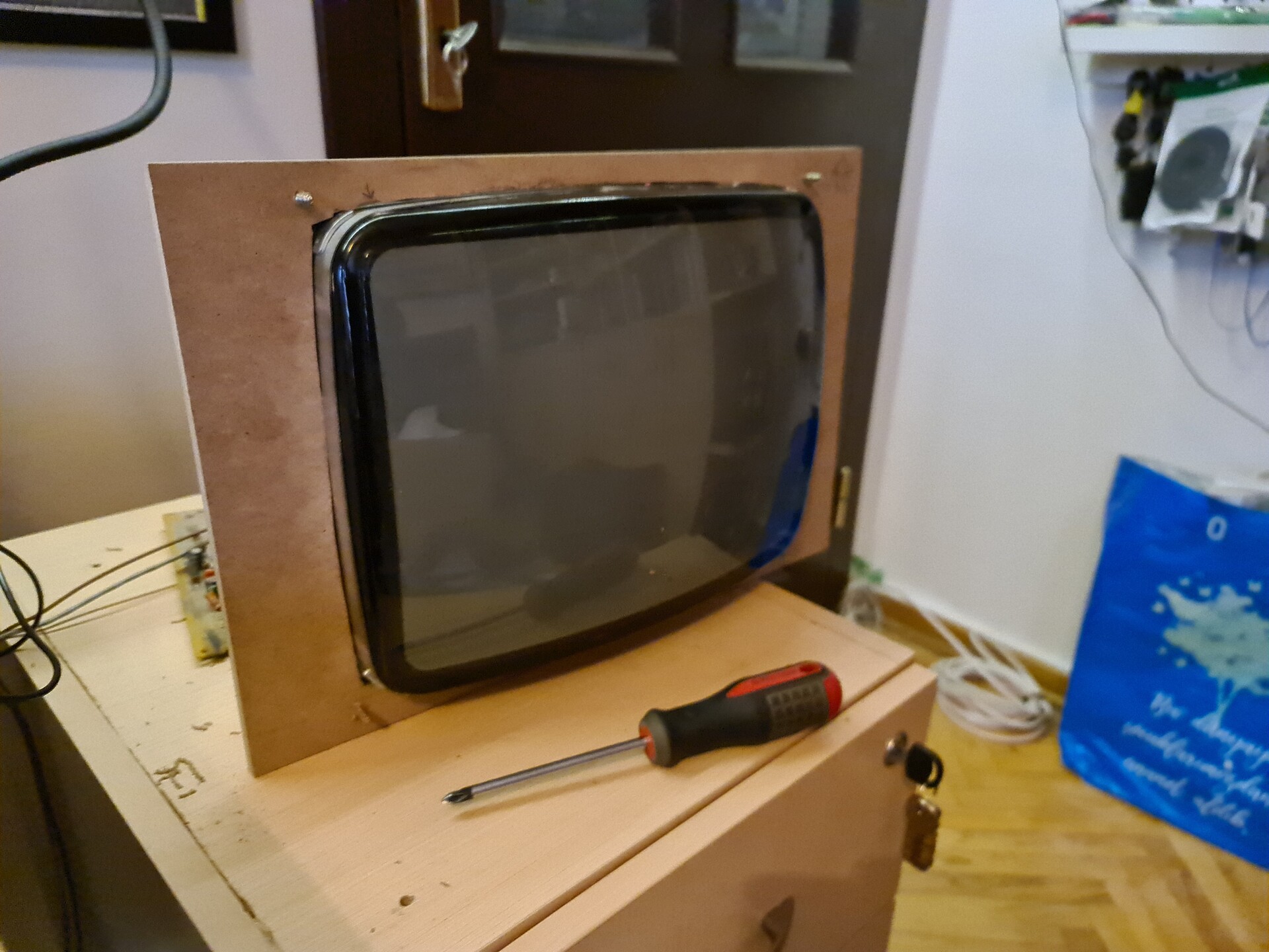
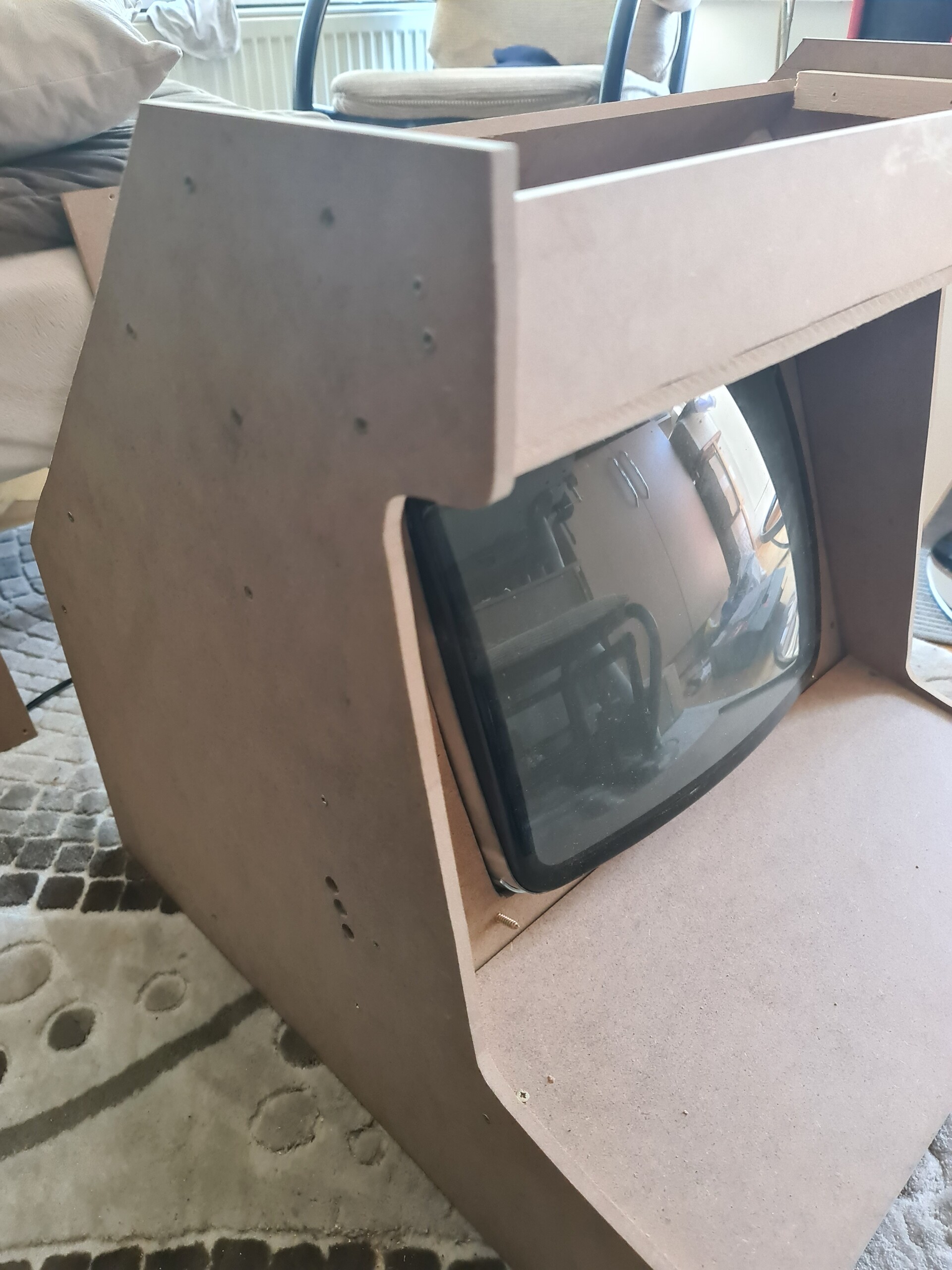
I started to cut the inside hole of the CRT panel first. It was hard to cut as a good linear way with Jigsaw tool but it will be easy to hide these mistakes.

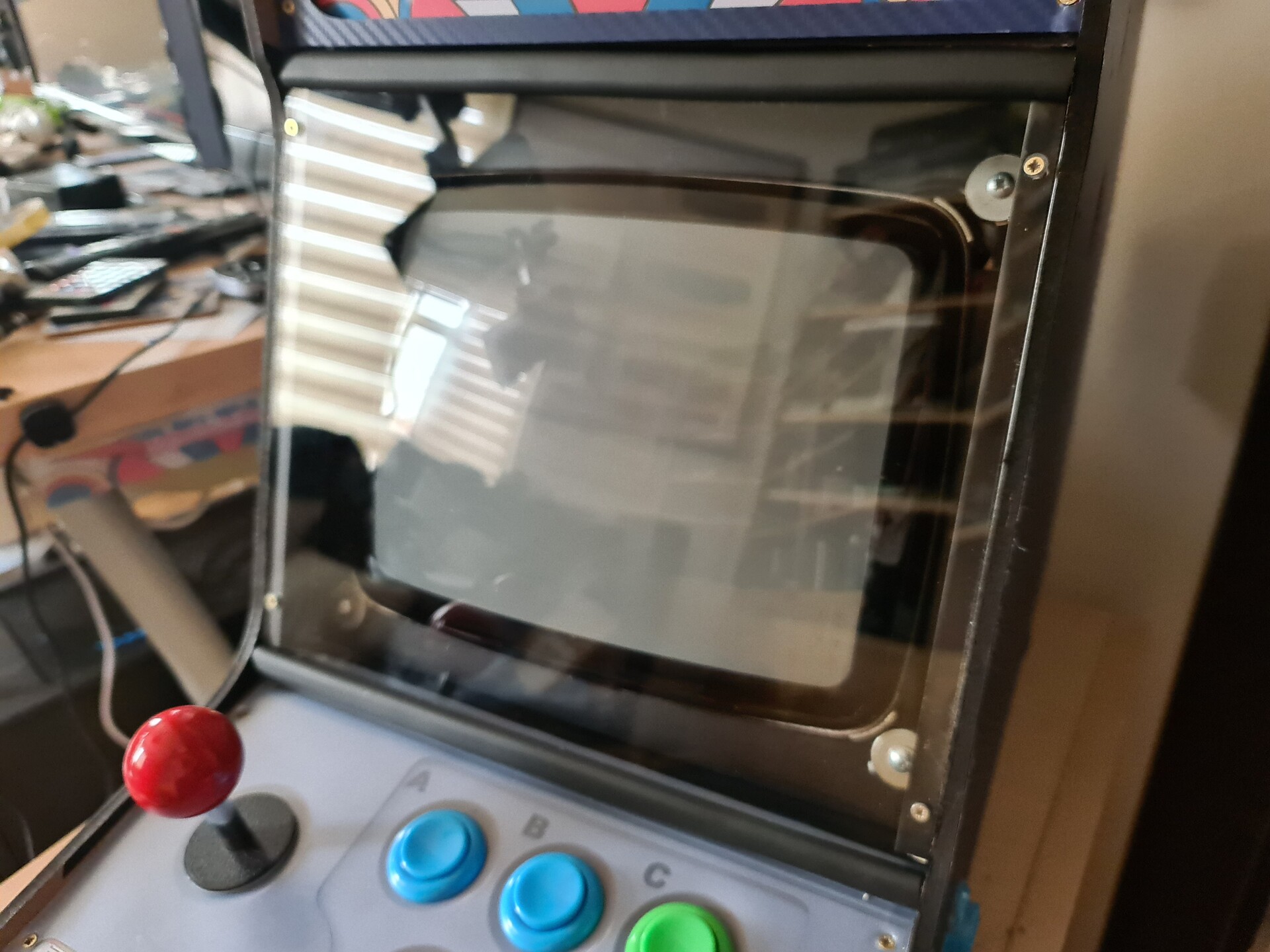
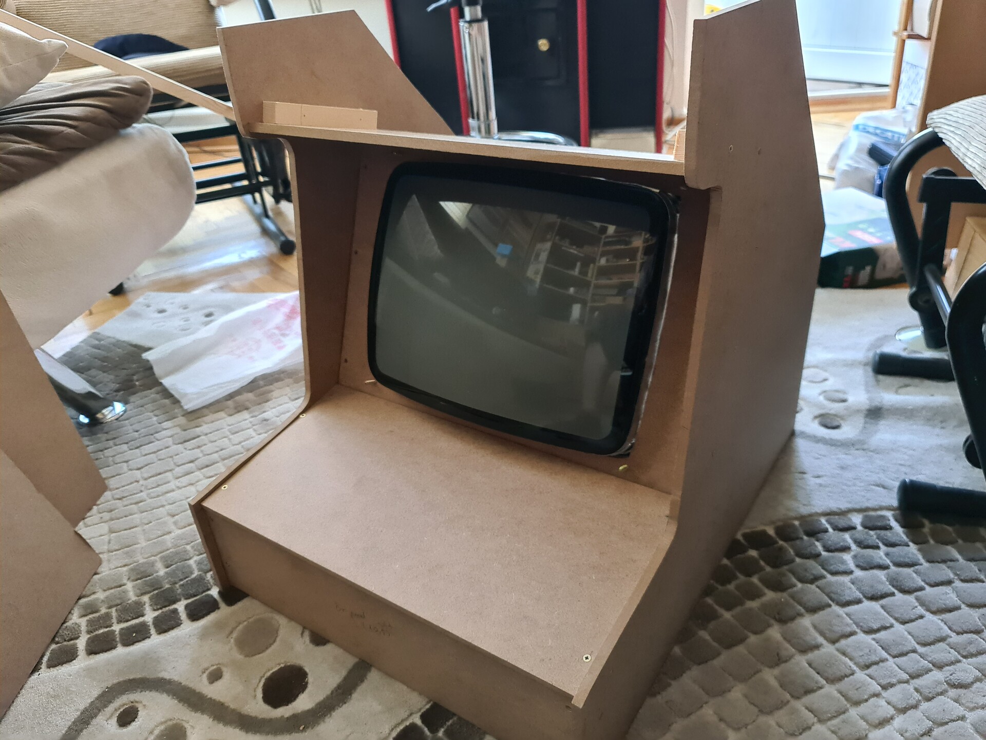
After cutting the front board, I fixed the CRT screen.

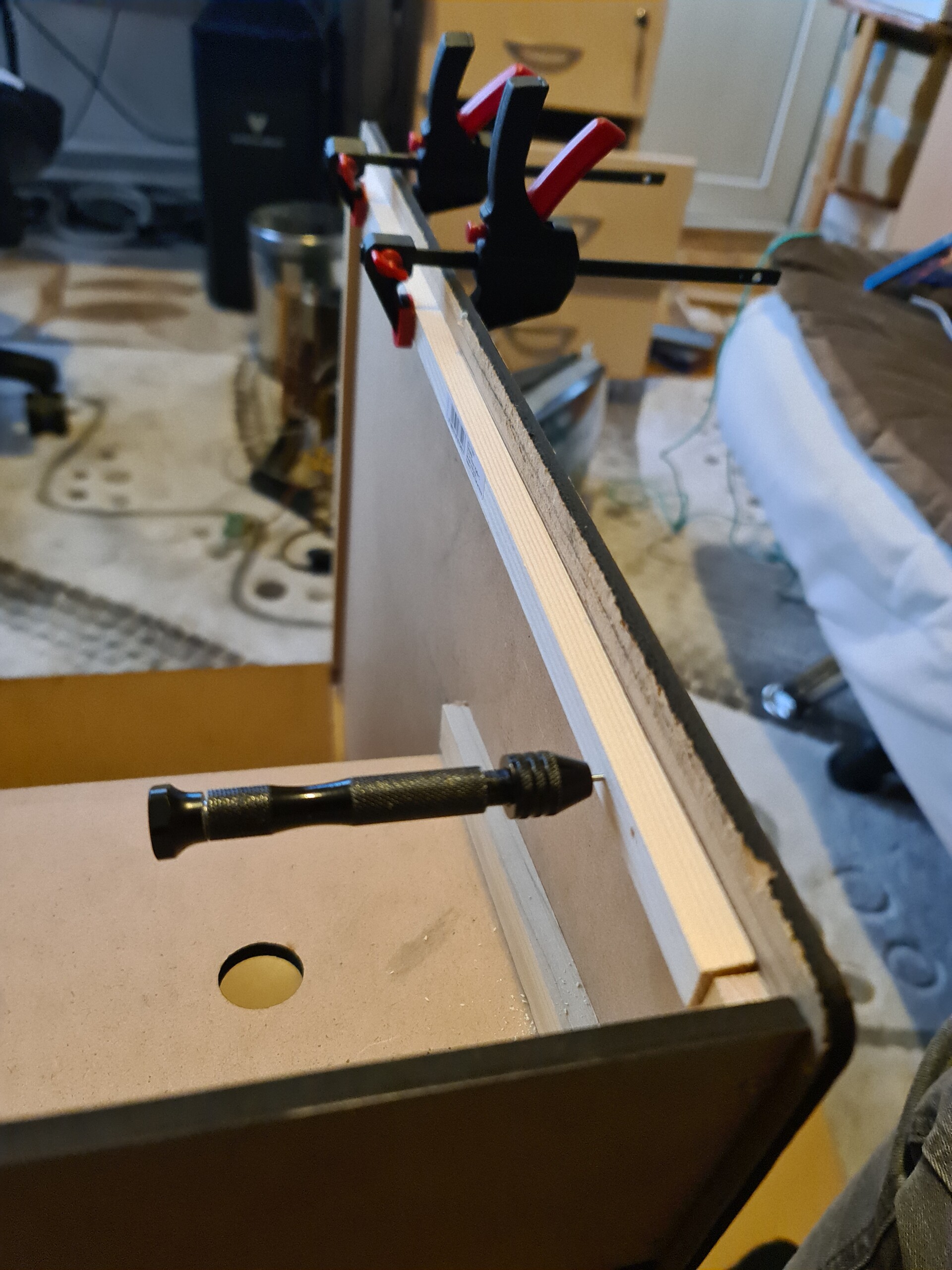
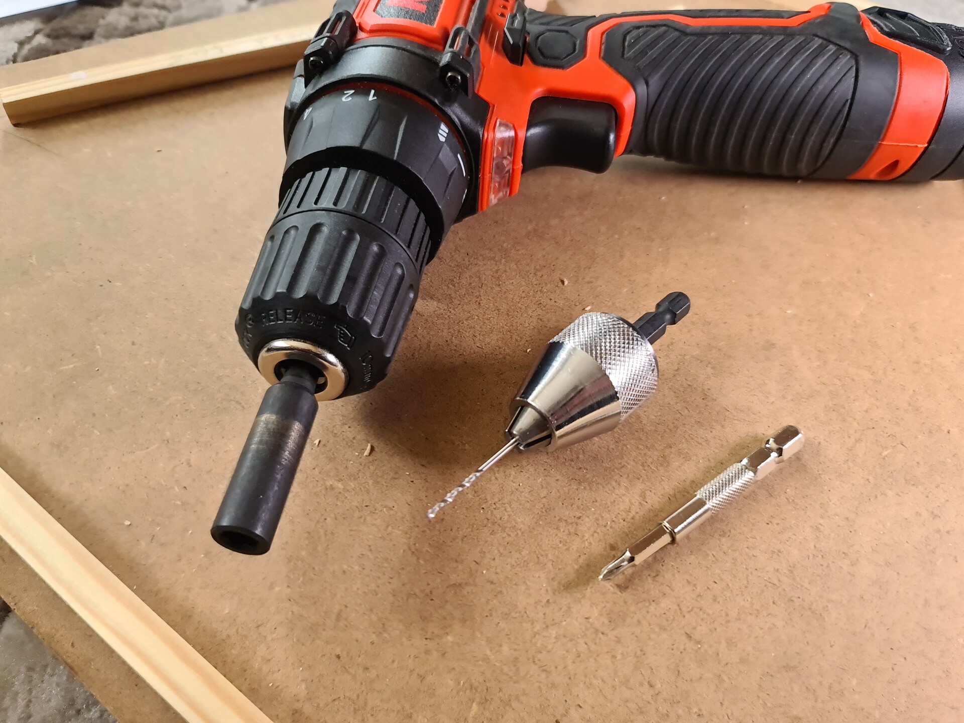
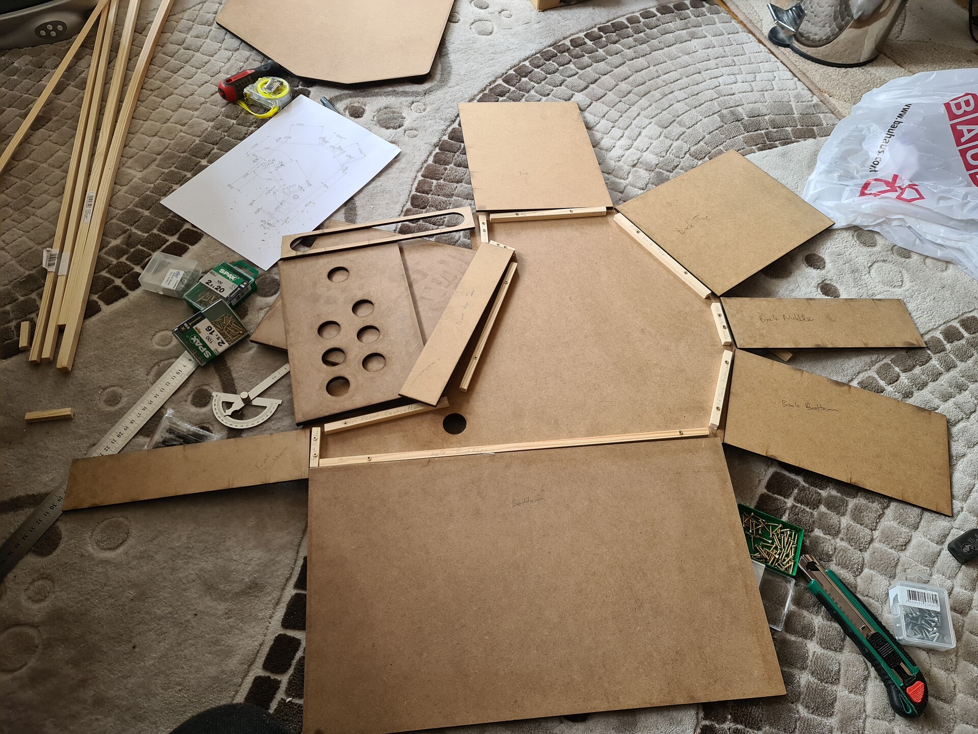
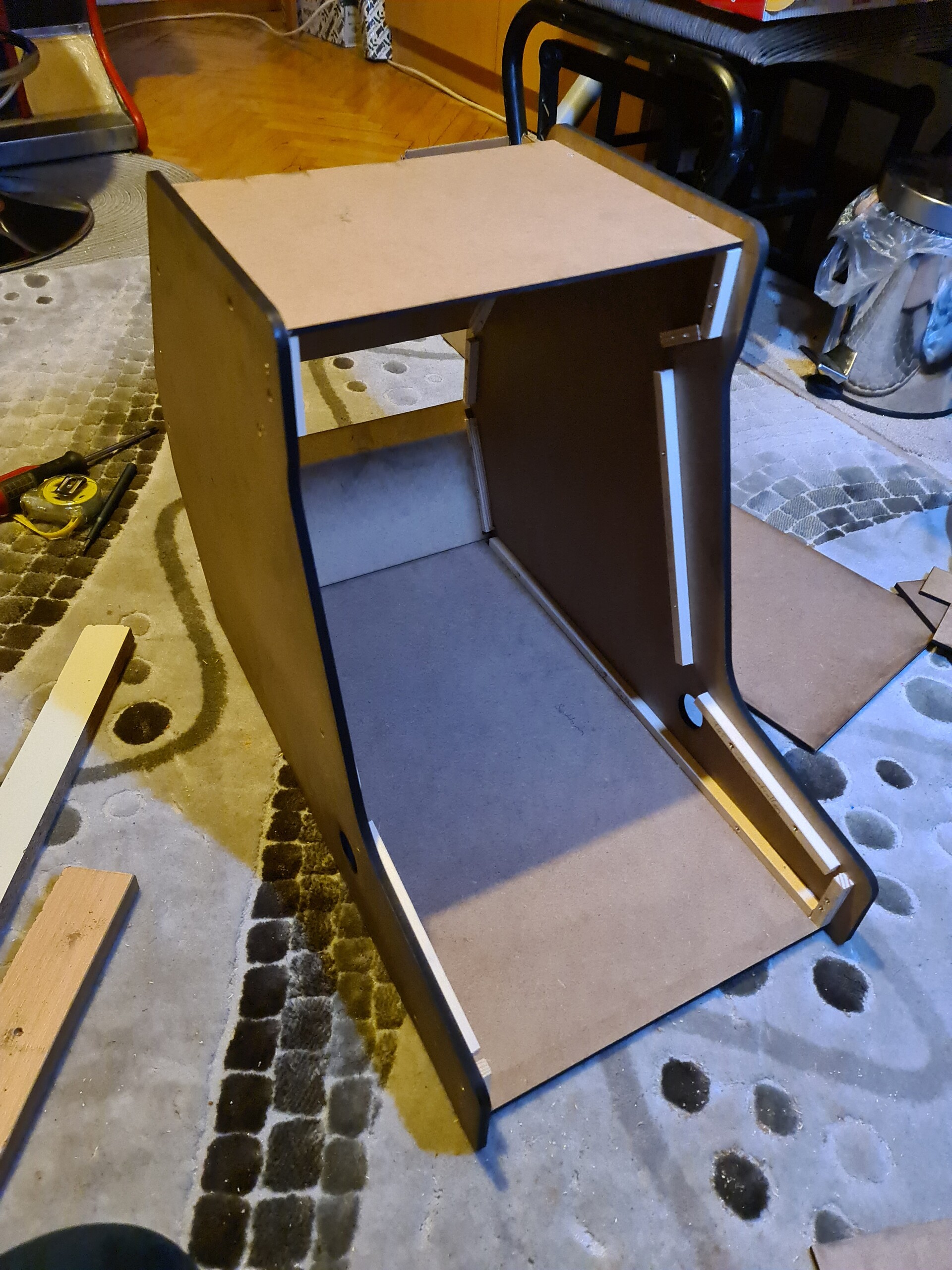
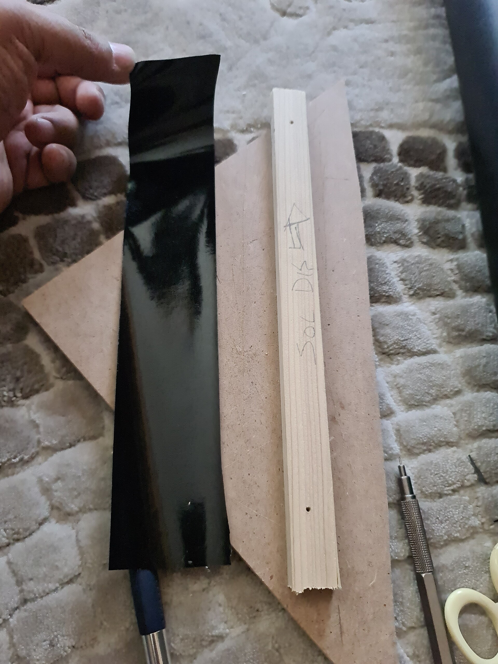
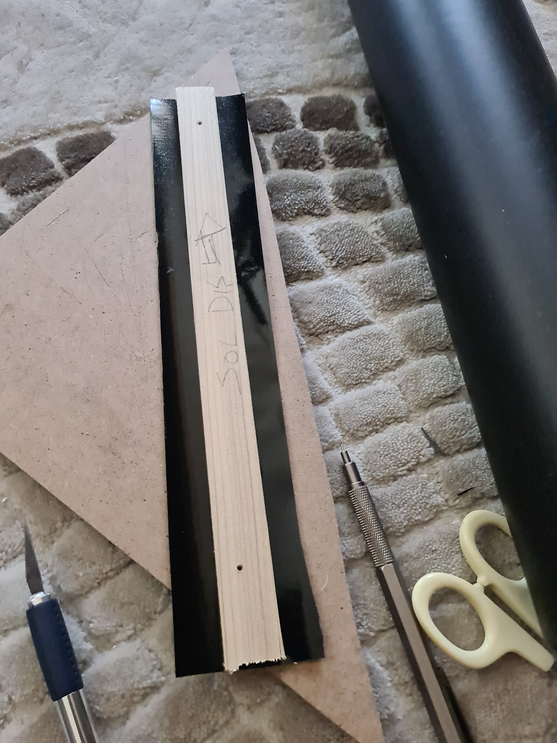
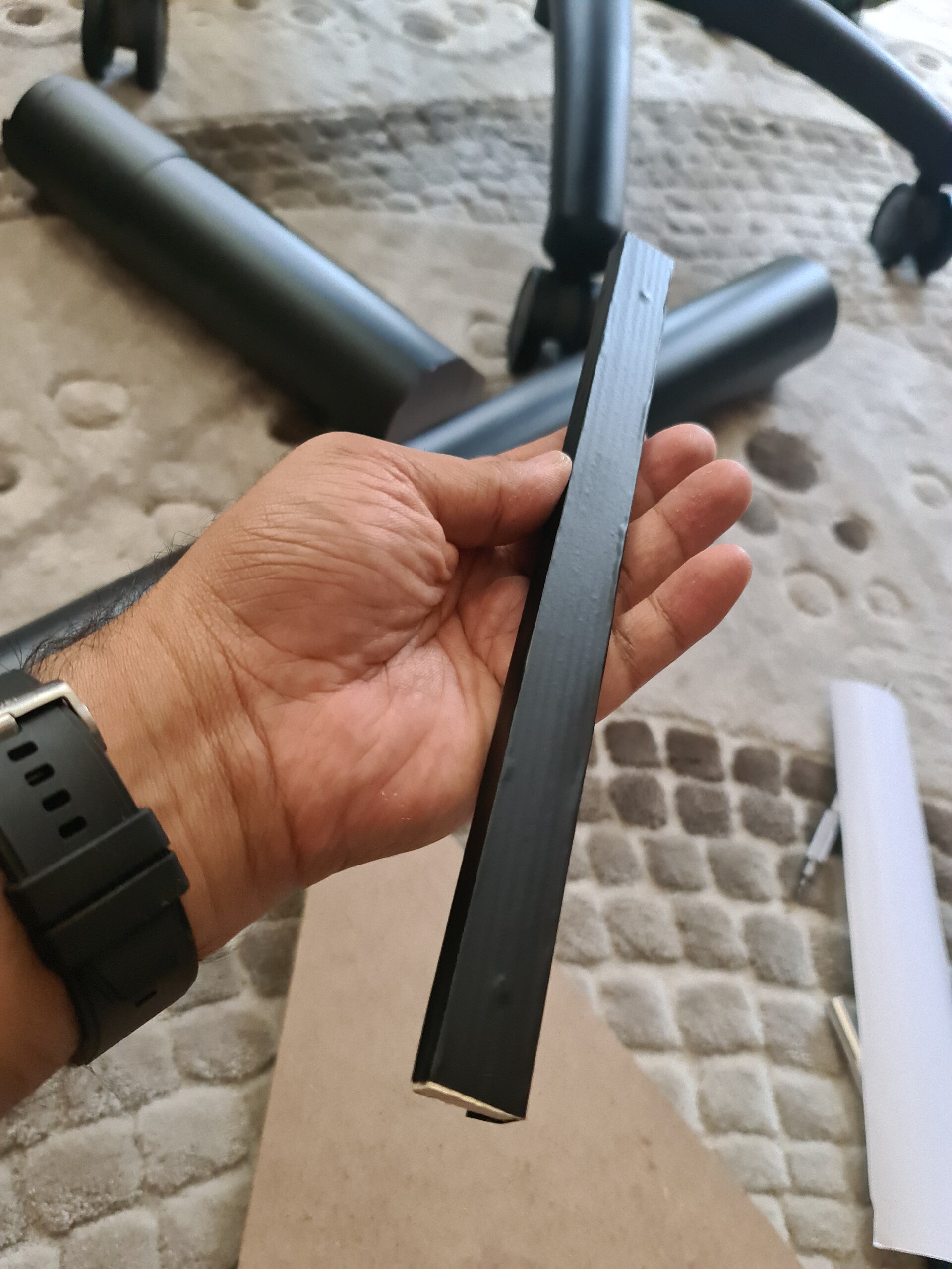
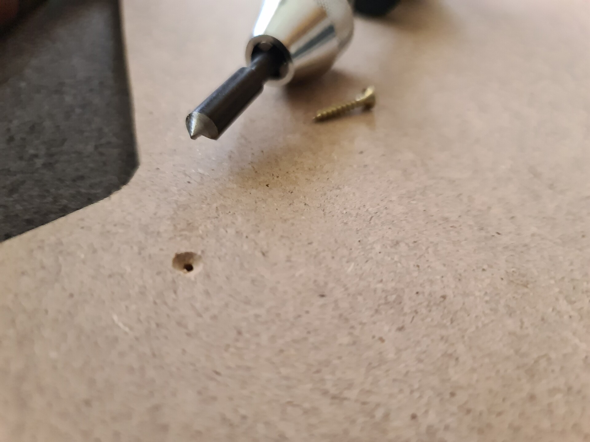
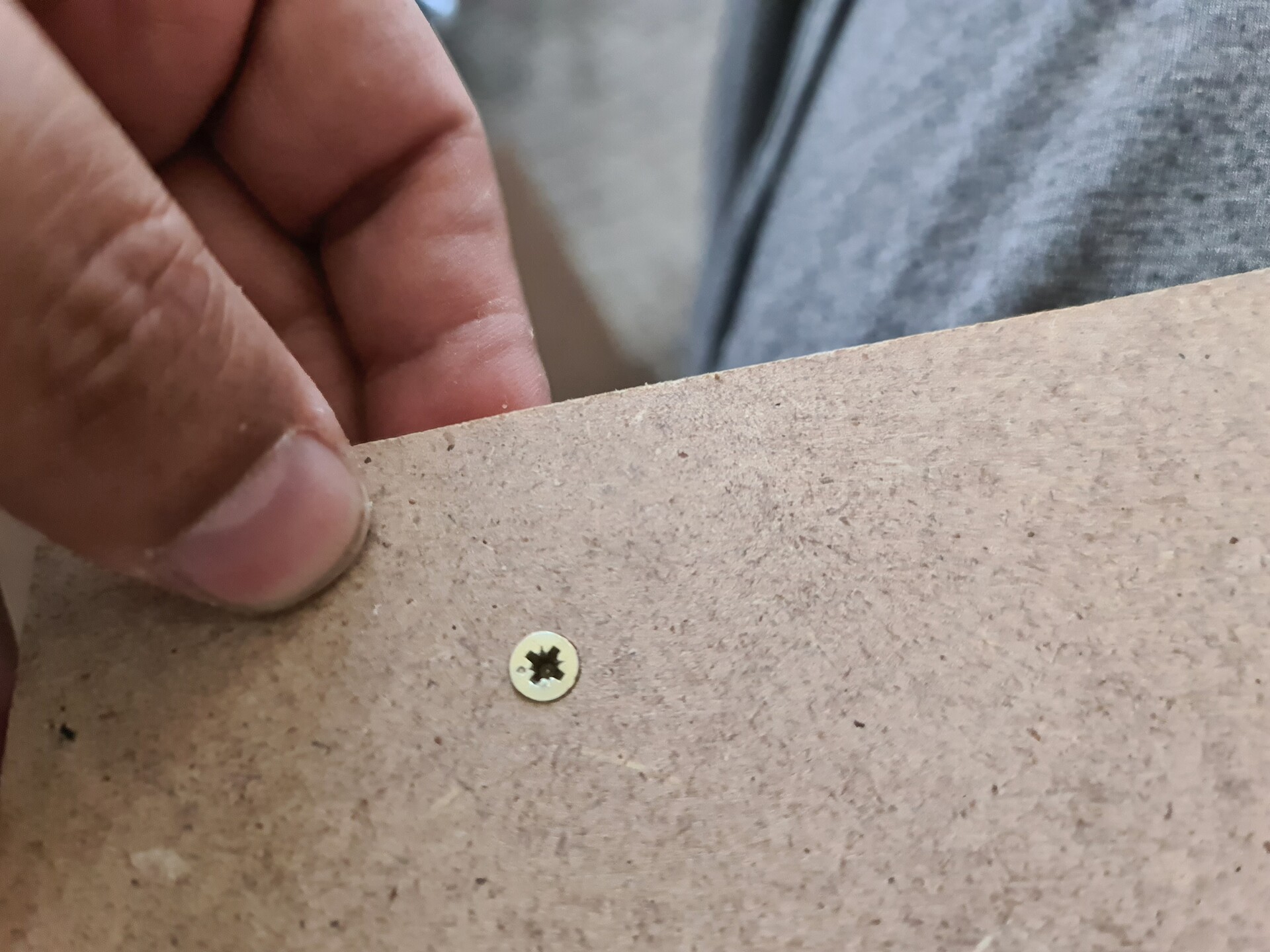
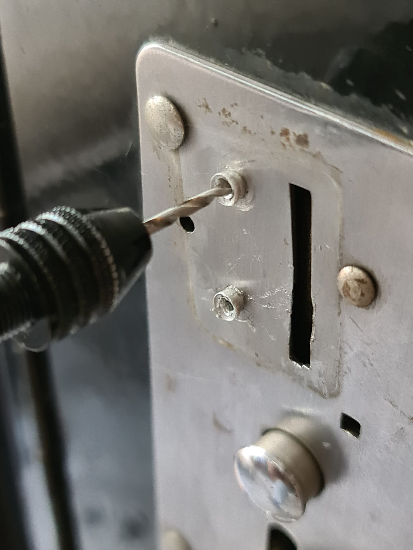
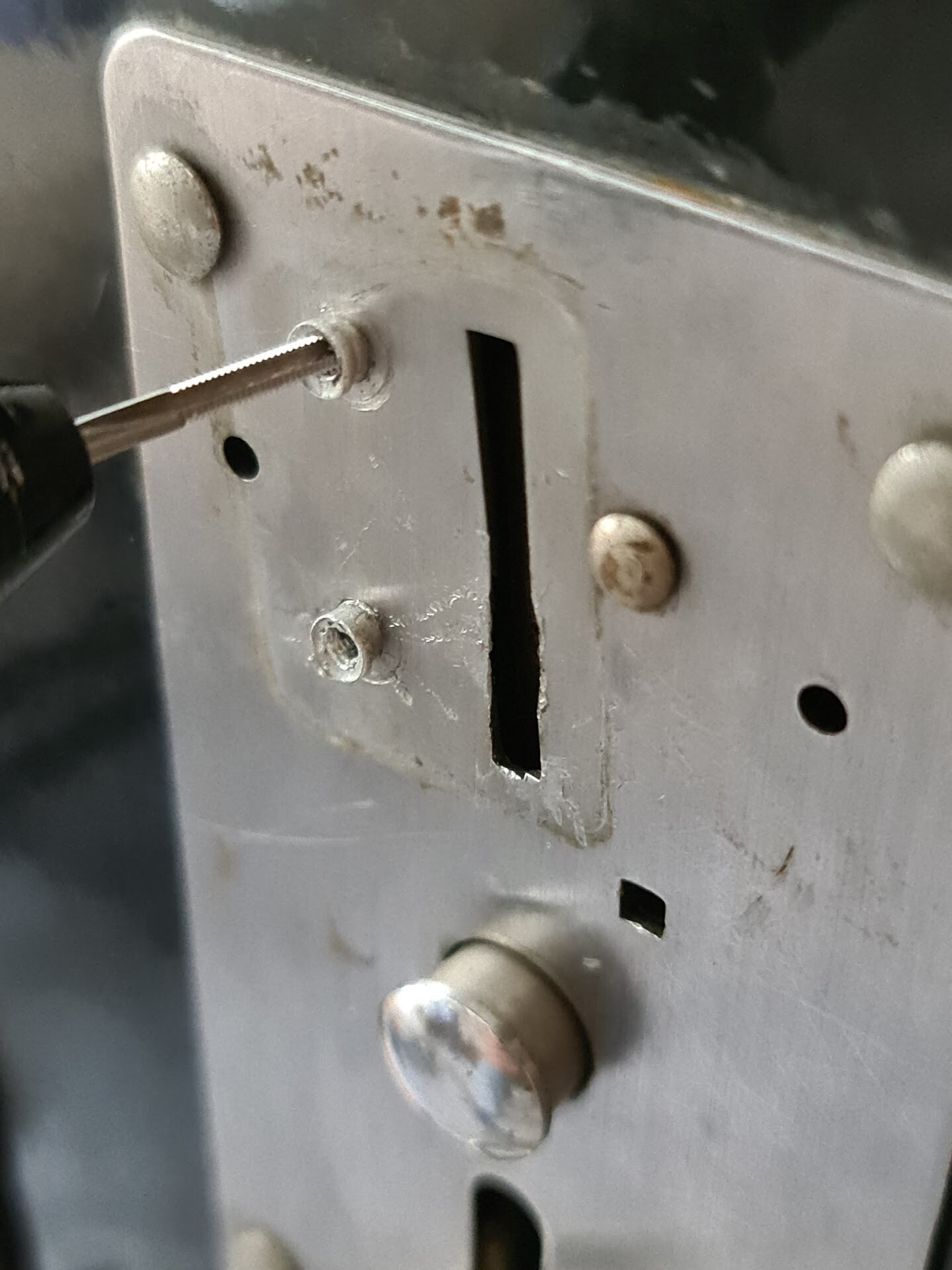
I cut the side parts as on my design and constructed the shape a little more. While I fix the parts with screw, I used a chamfering tool to make the screws planar with the surface, to get a better look.

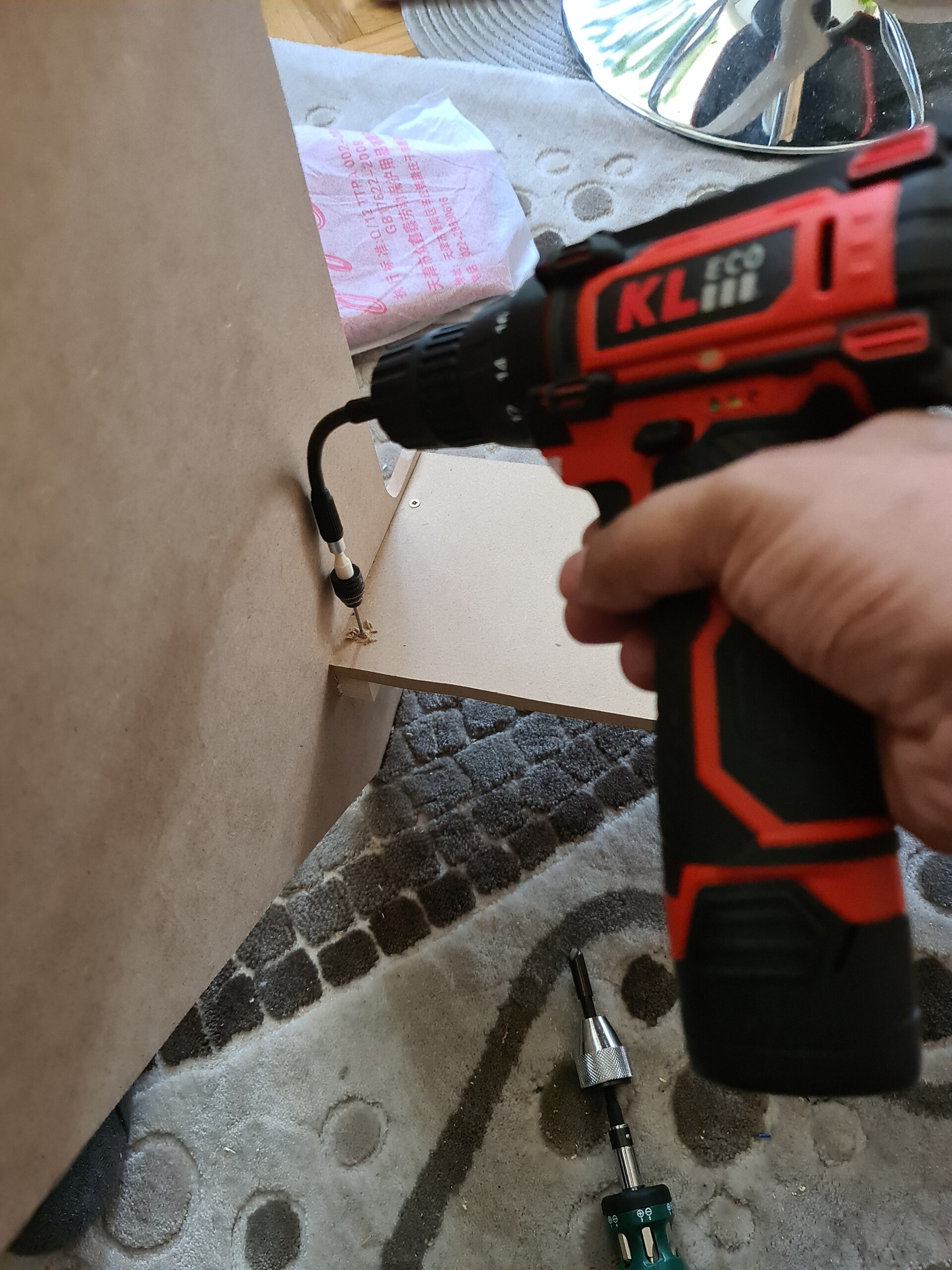
For drilling the hard positions, I used this flex screwing apparatus which was real helpful for those cases.

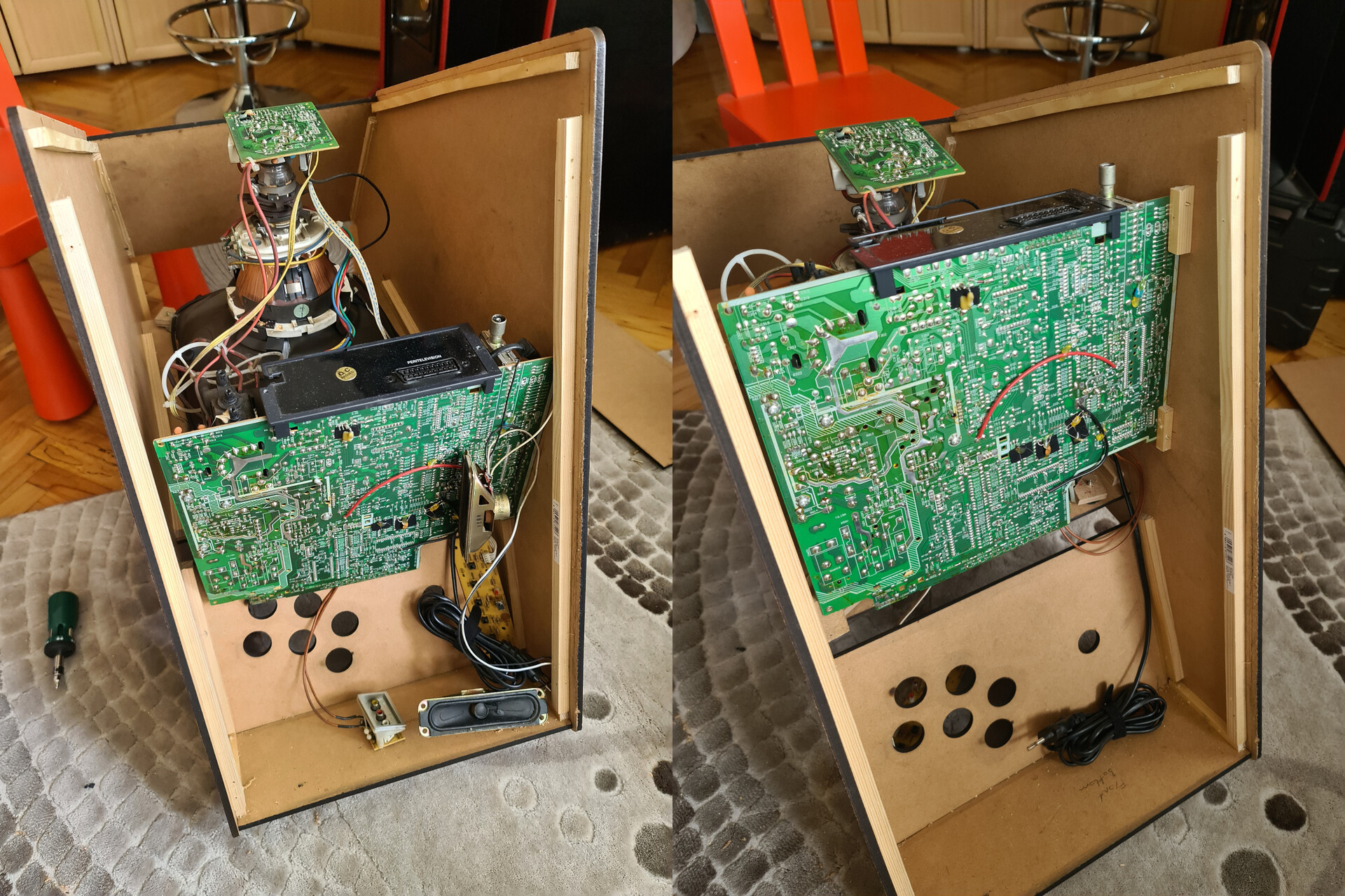
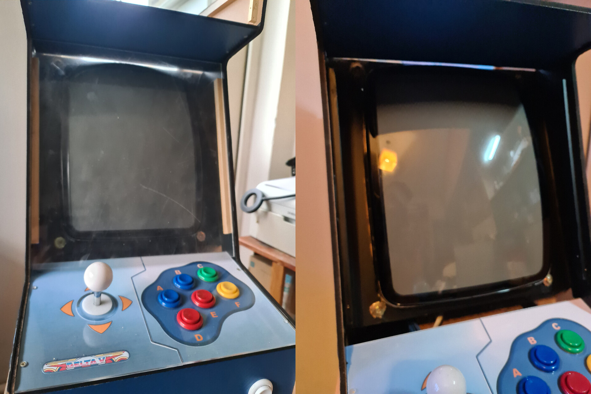
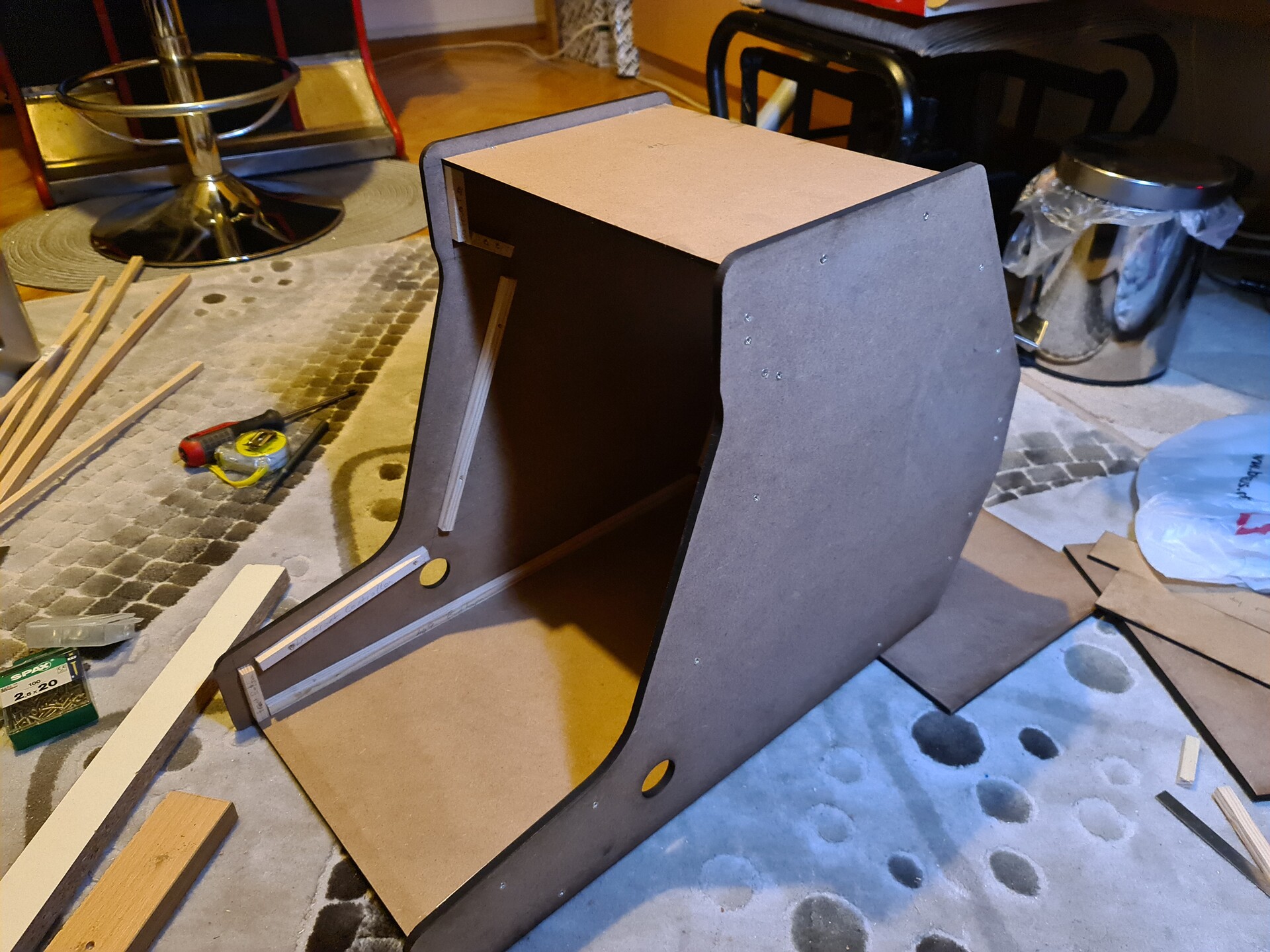
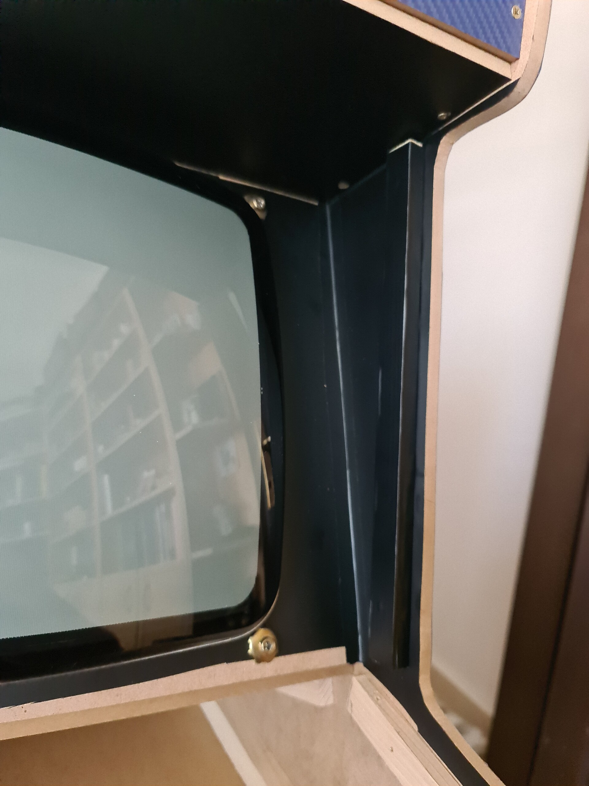
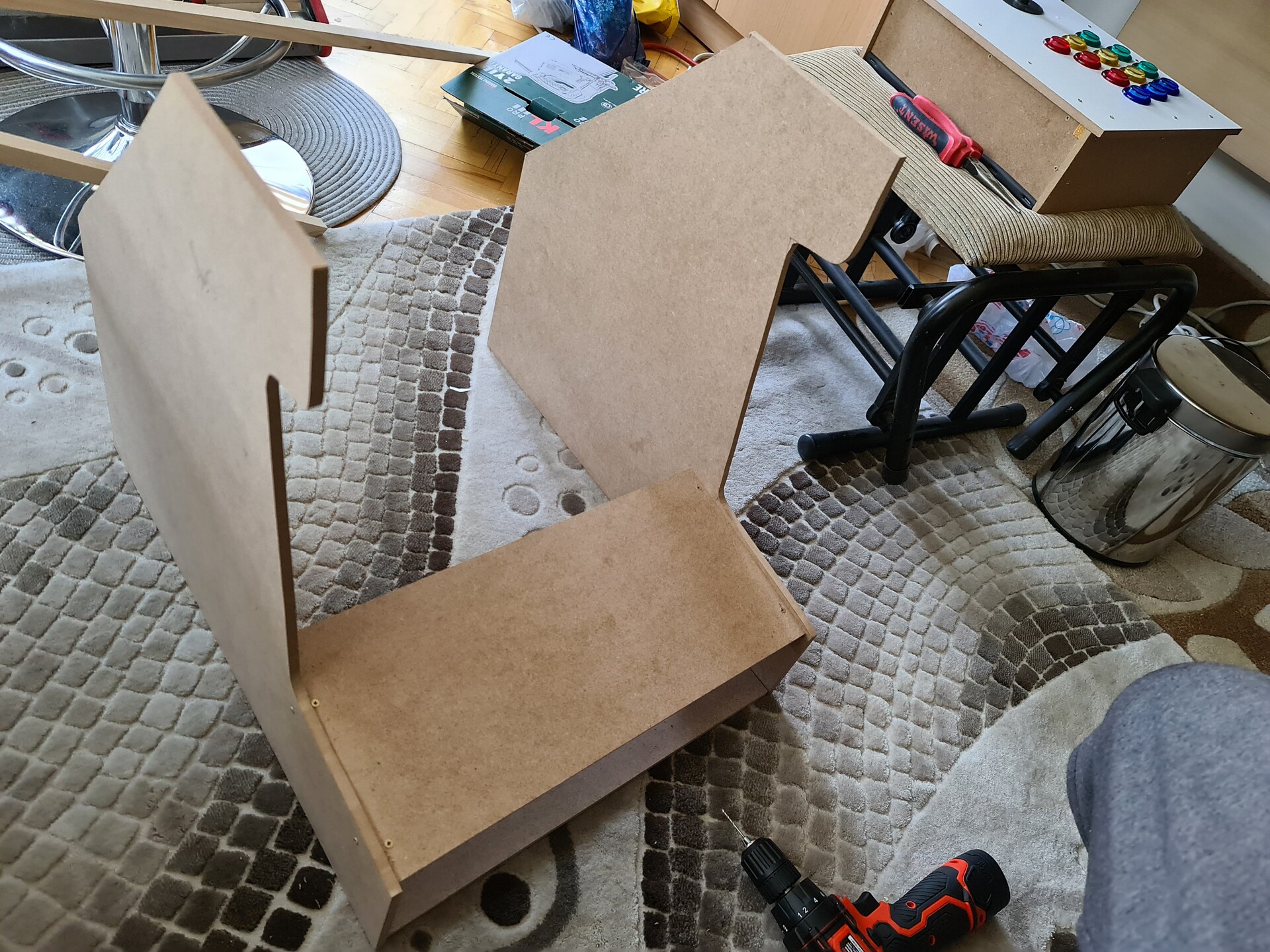
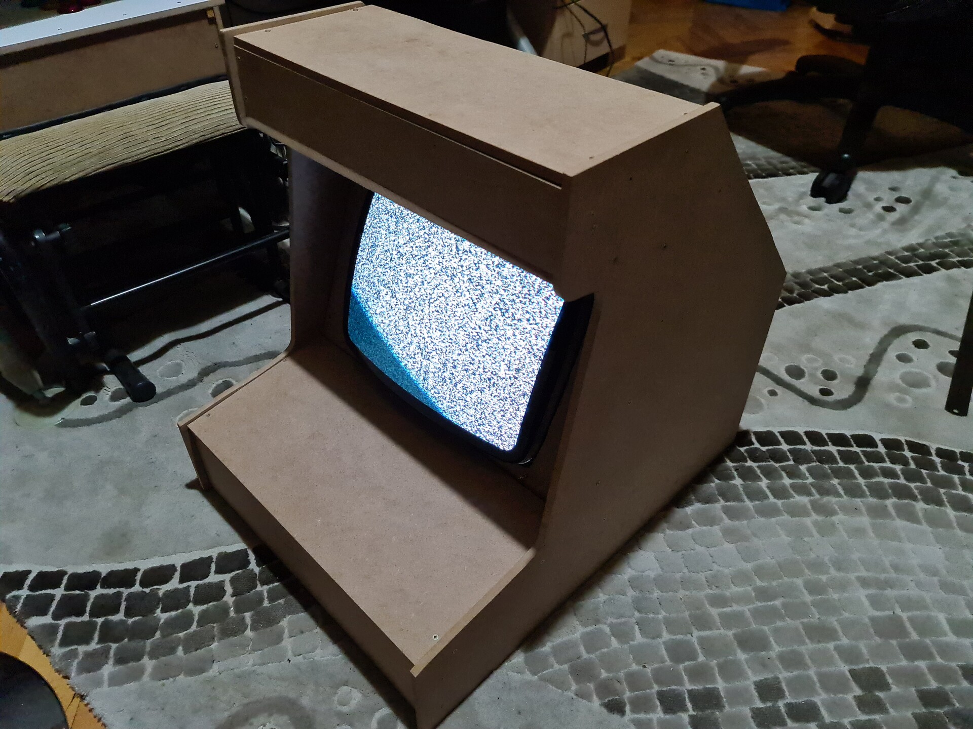
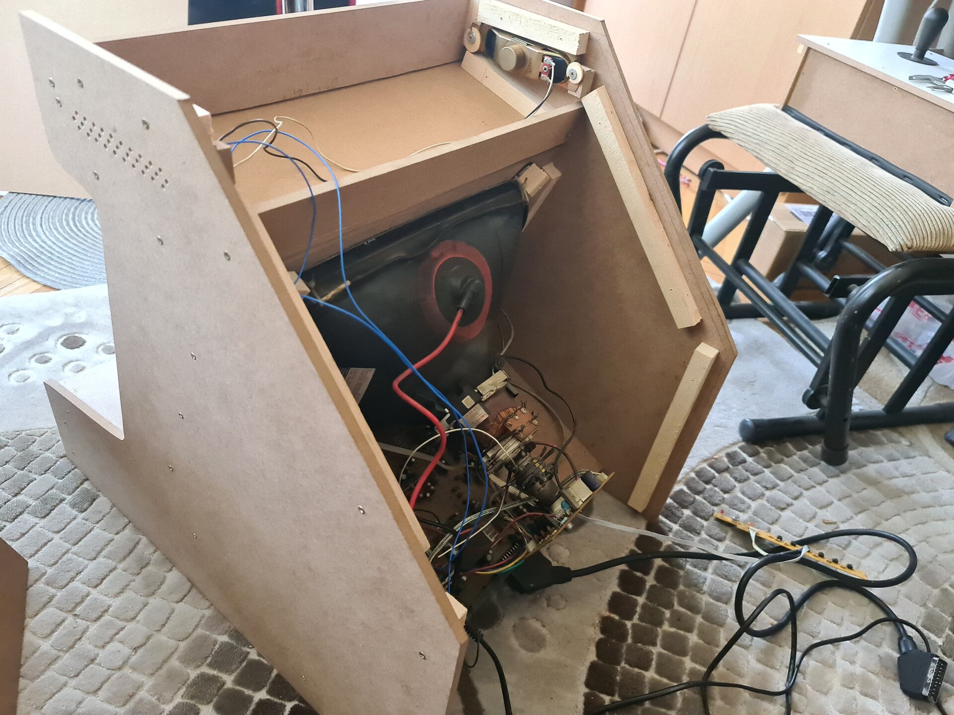
I moved on constructing the cabinet with the same approach and placed the screen as well.

The most important part is since the screen is not discharged, I needed to close up the cabinet as soon as possible. So I fixed the back side boards and tested the system.

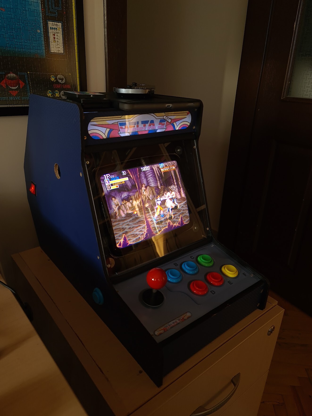
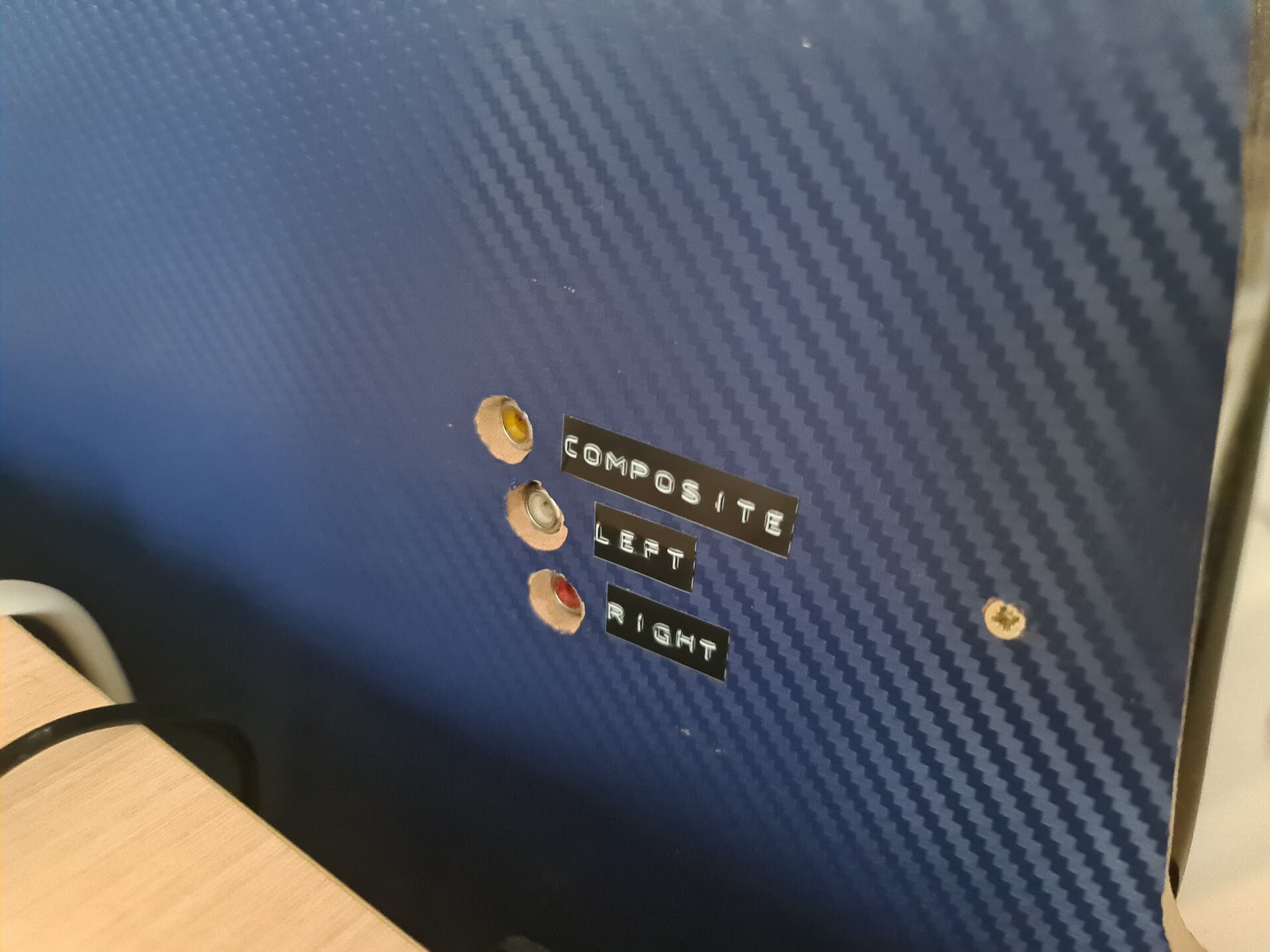
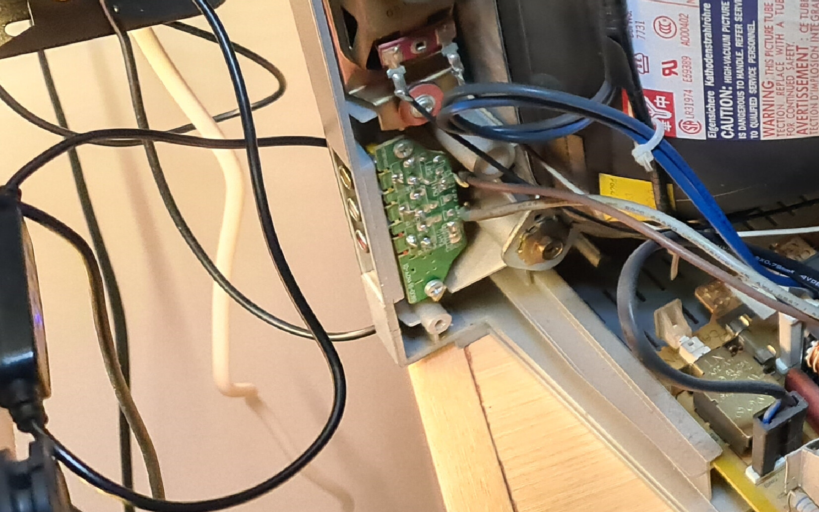
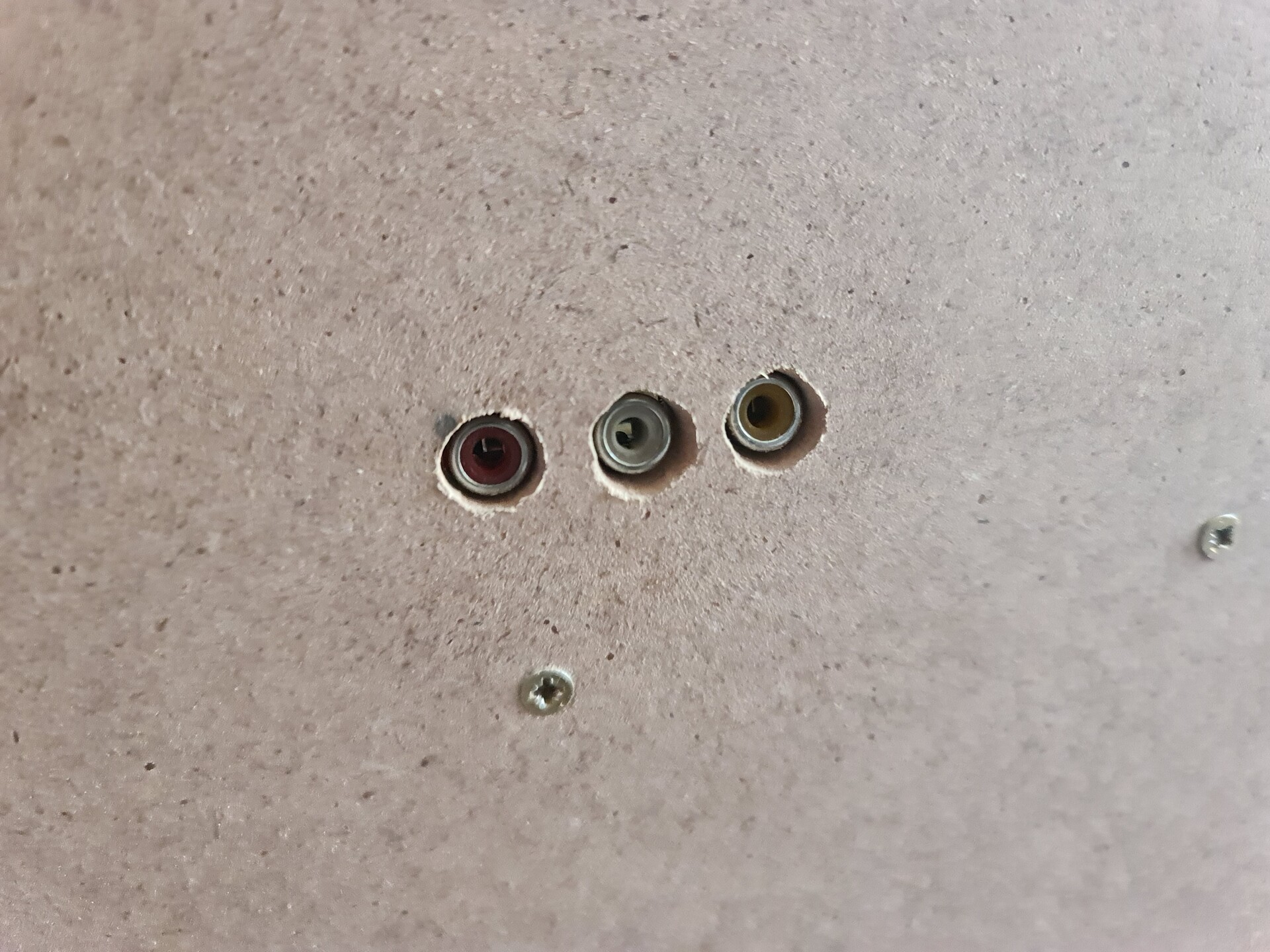
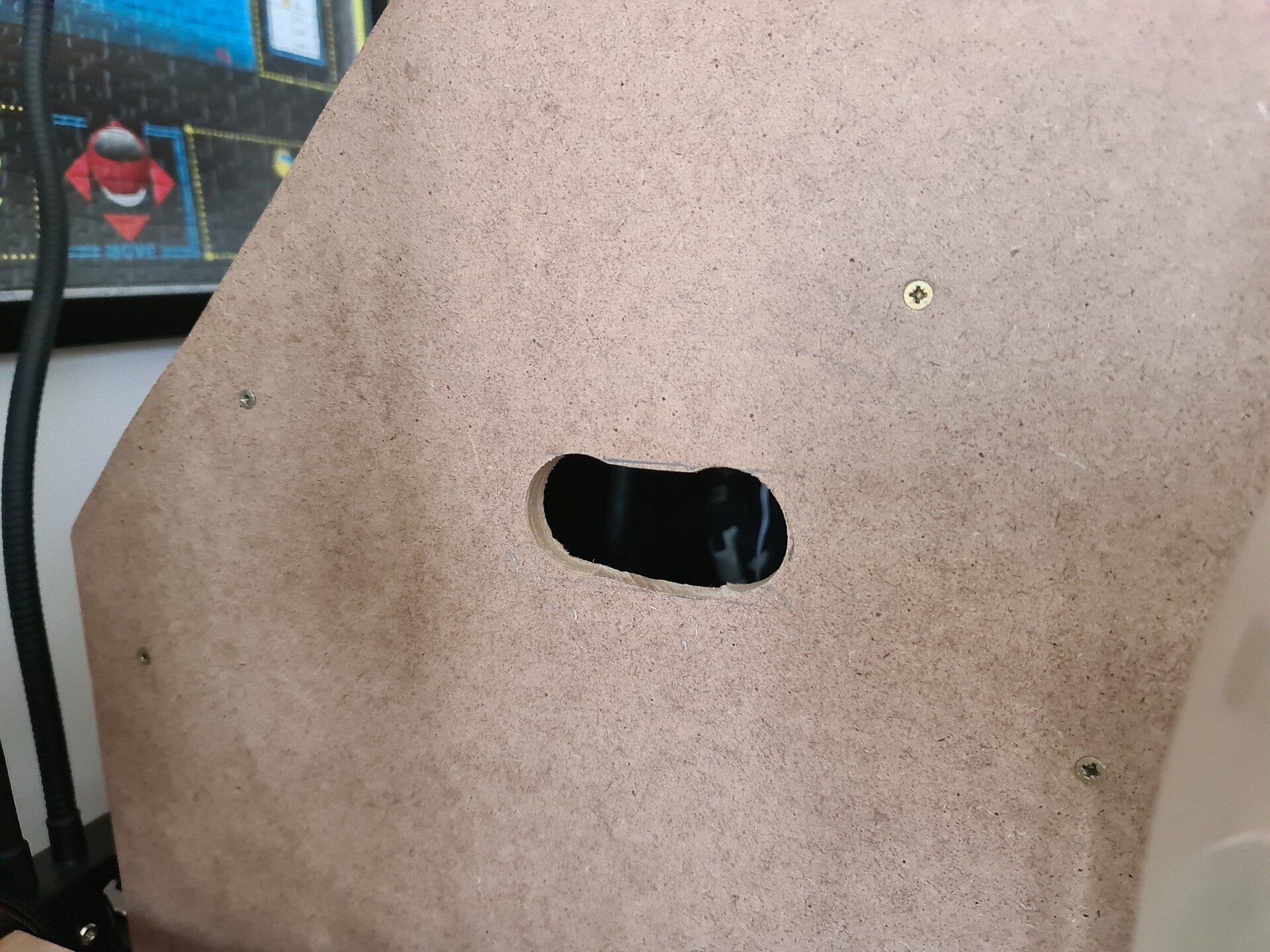
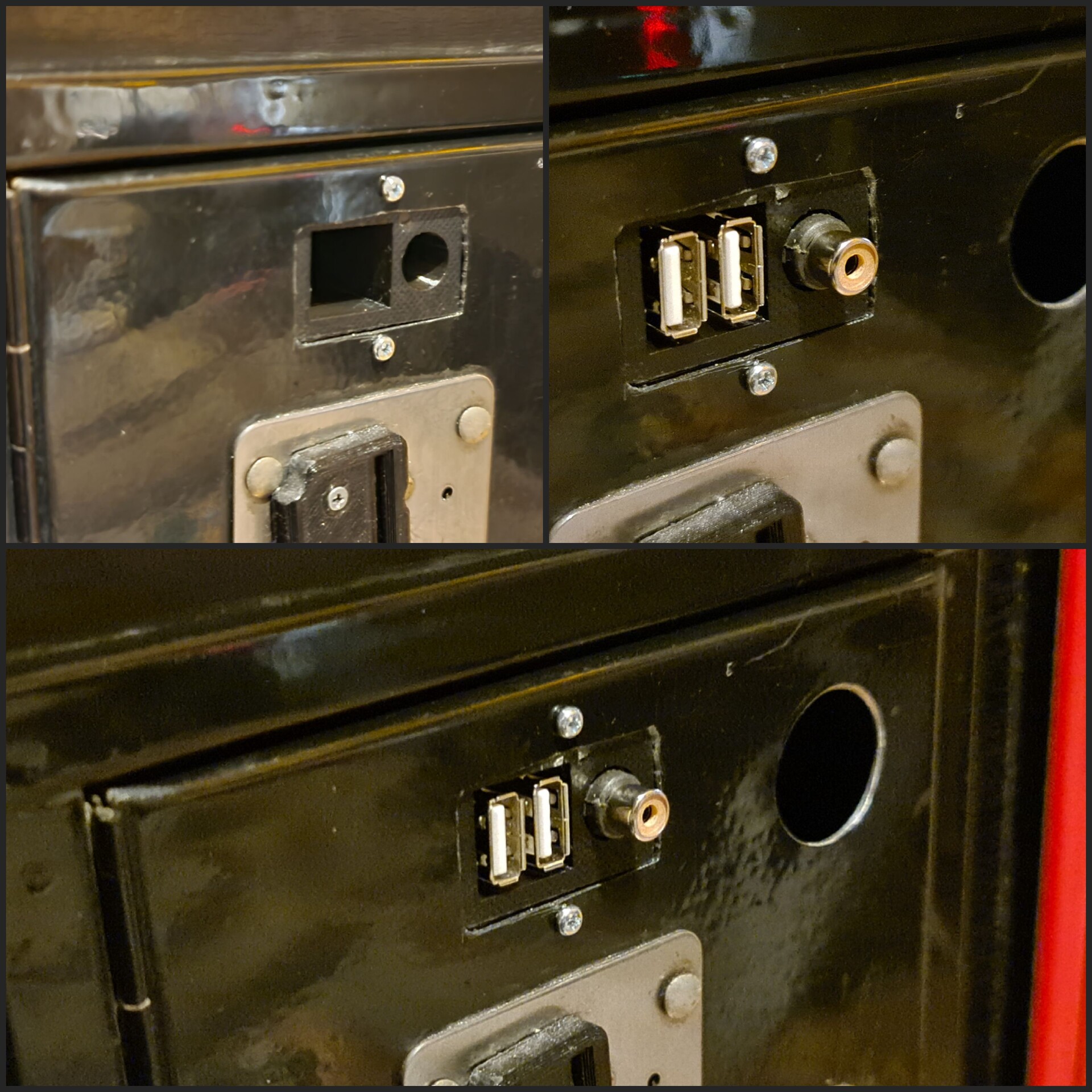
This TV system had a RCA input as well. 

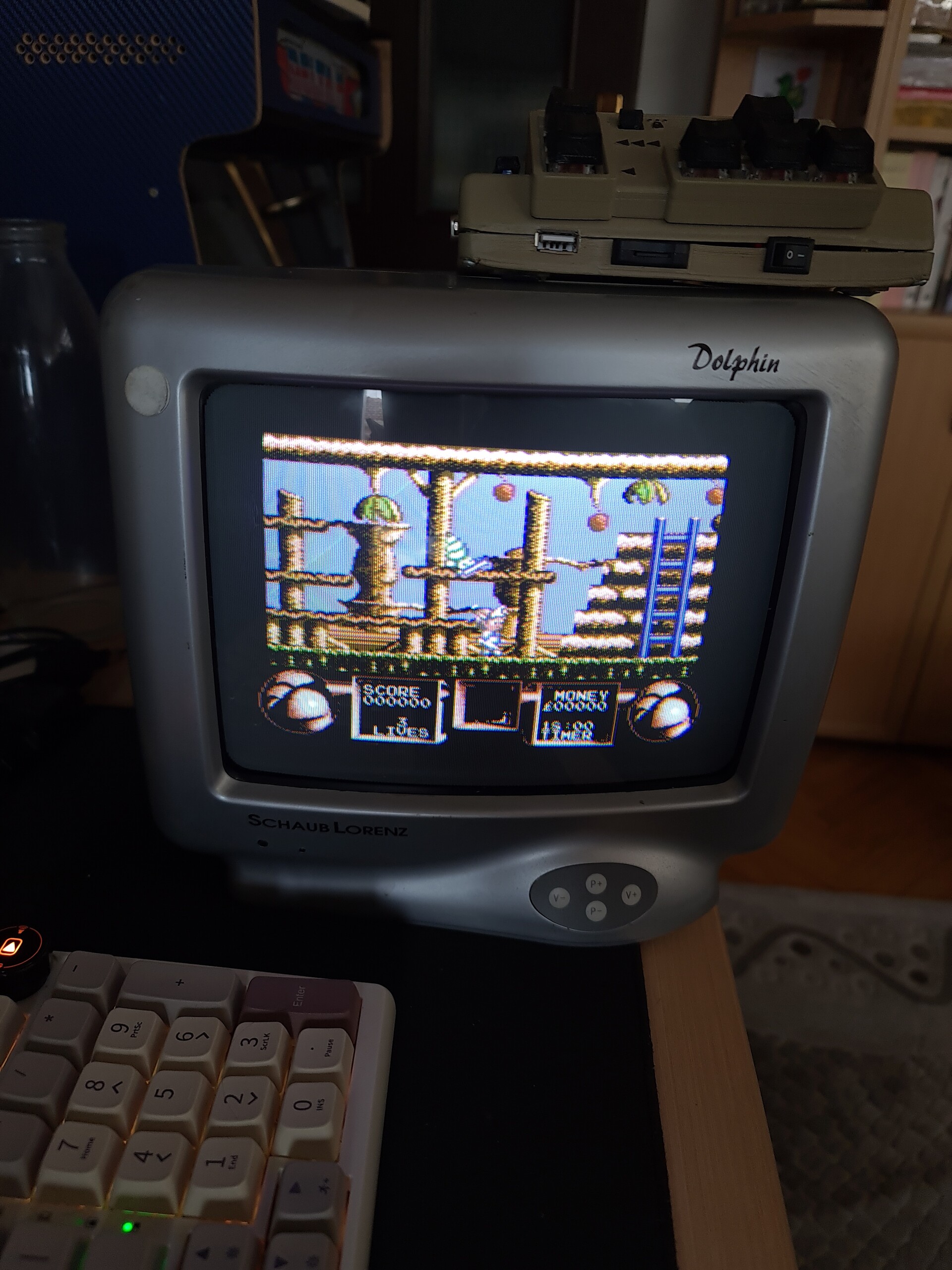
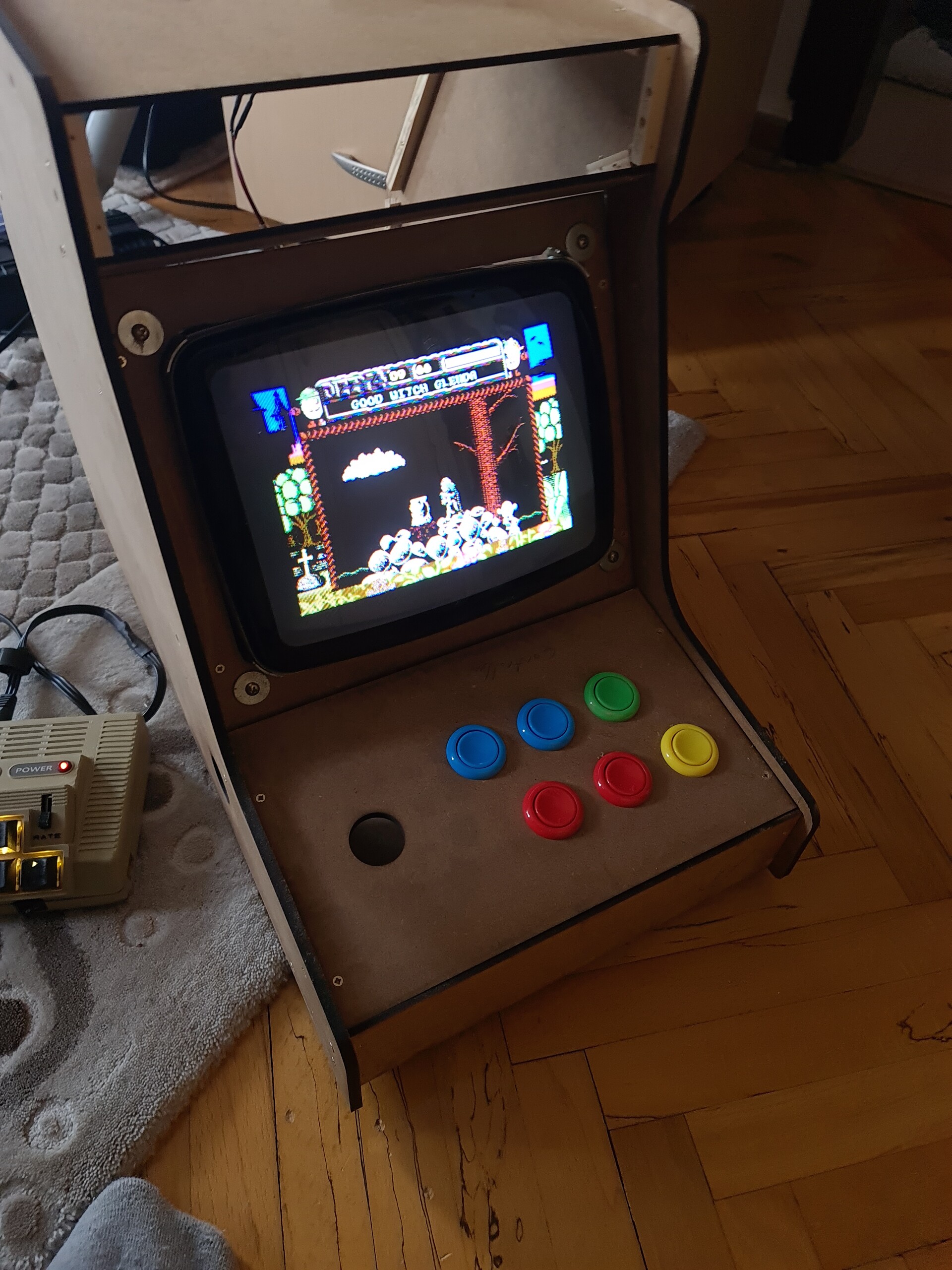
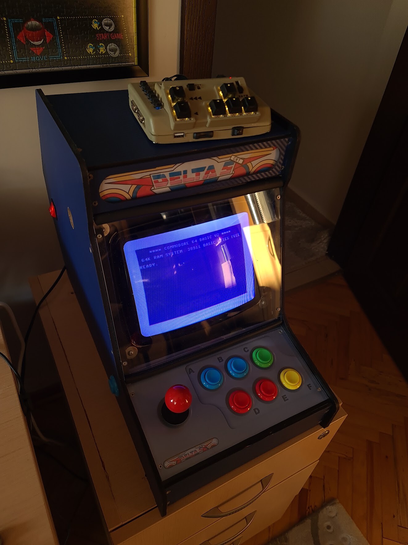
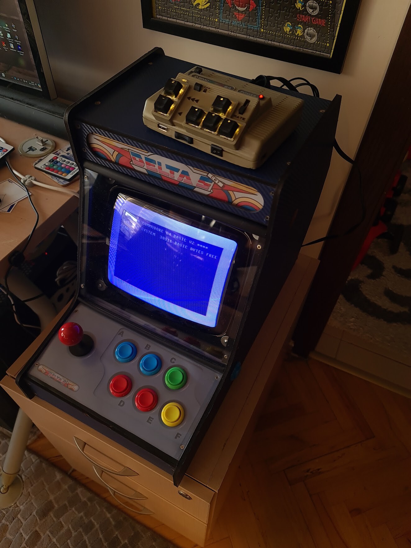
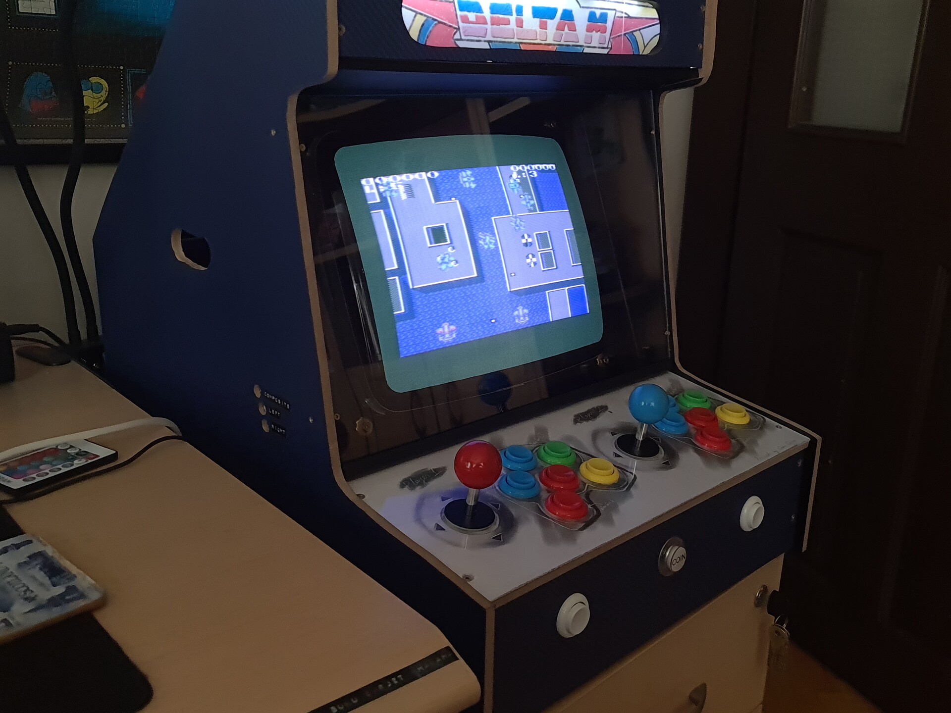
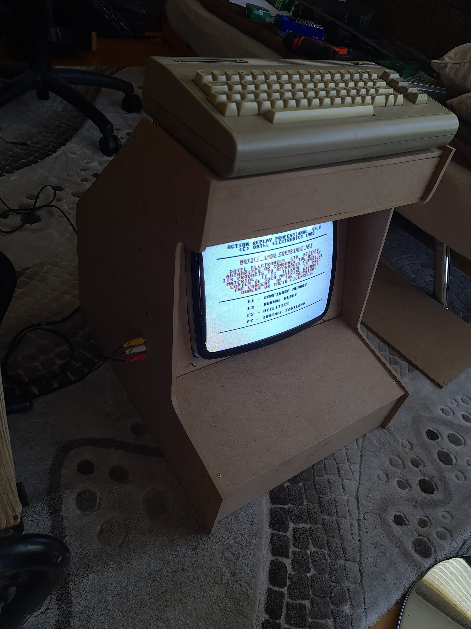
I moved that port to the side of my cabinet to use the system as a screen for other consoles as well. Also I could use this port to connect my Commodore 64 to the cabinet.

I tested the port with my Commodore 64.

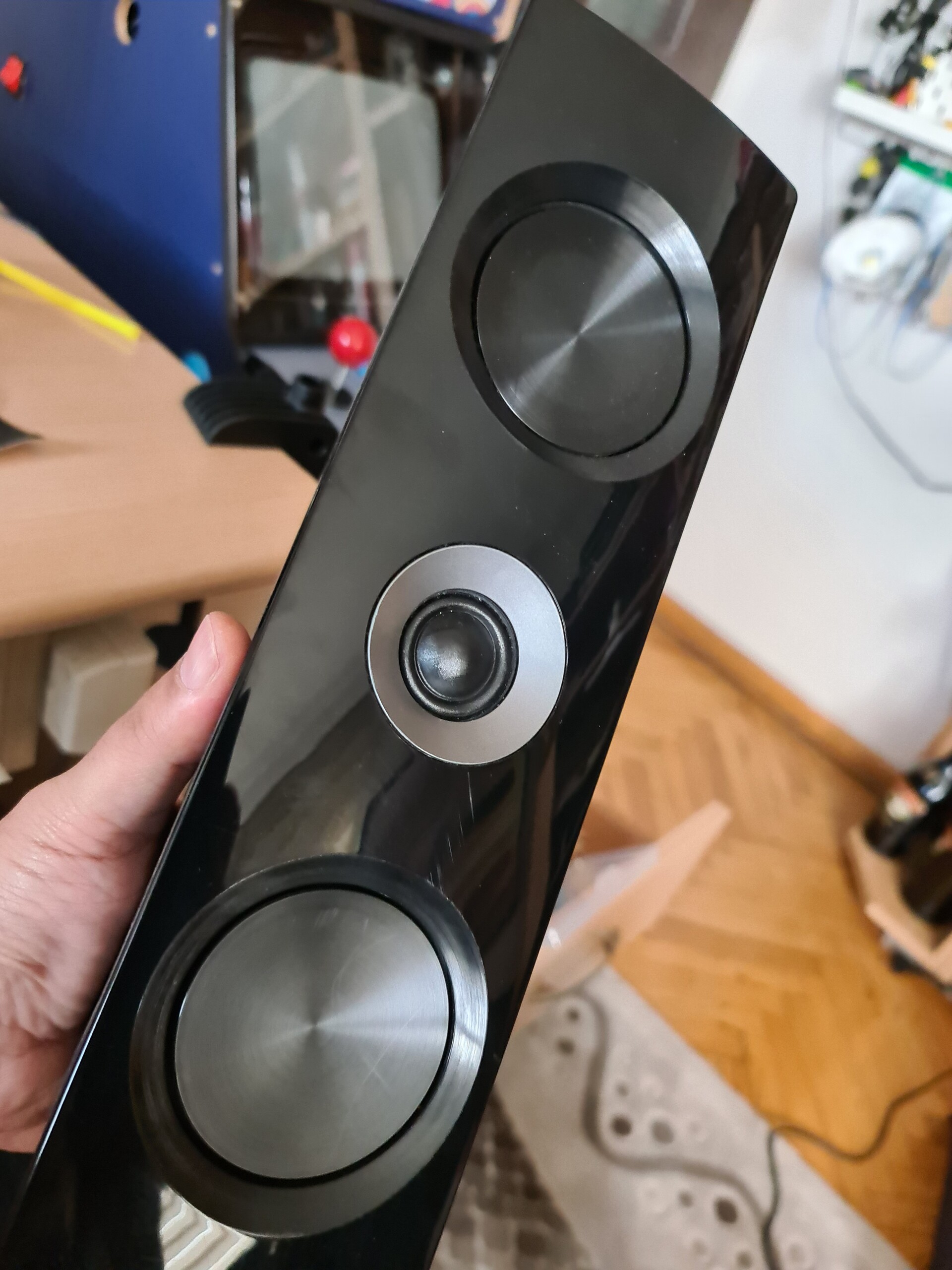
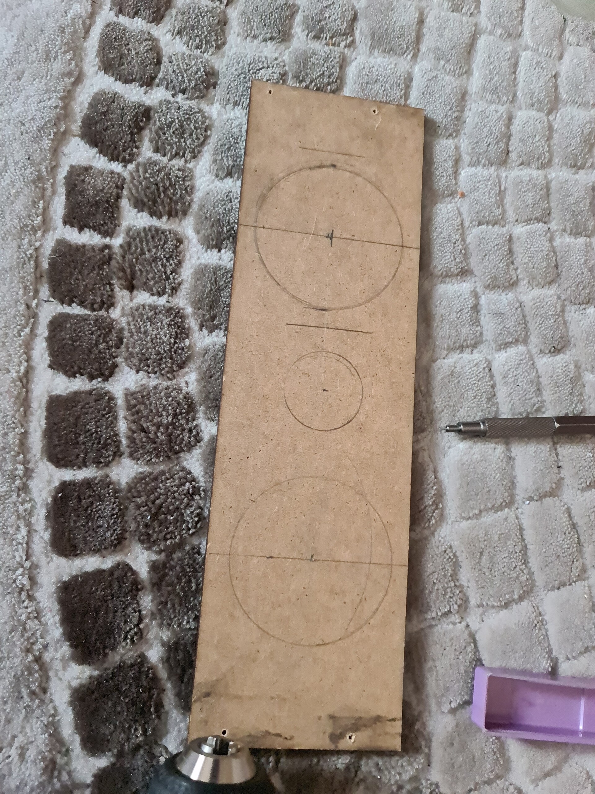
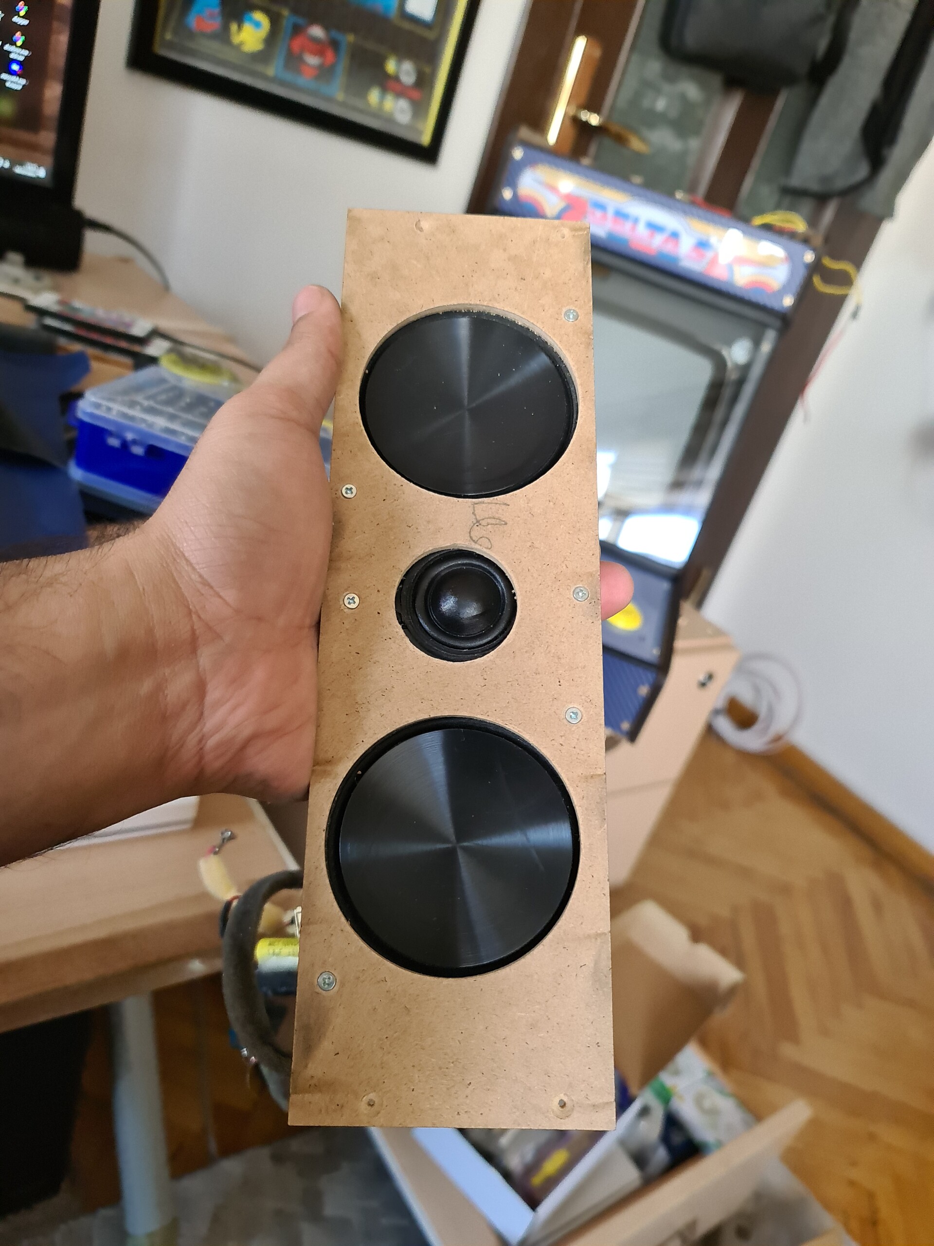
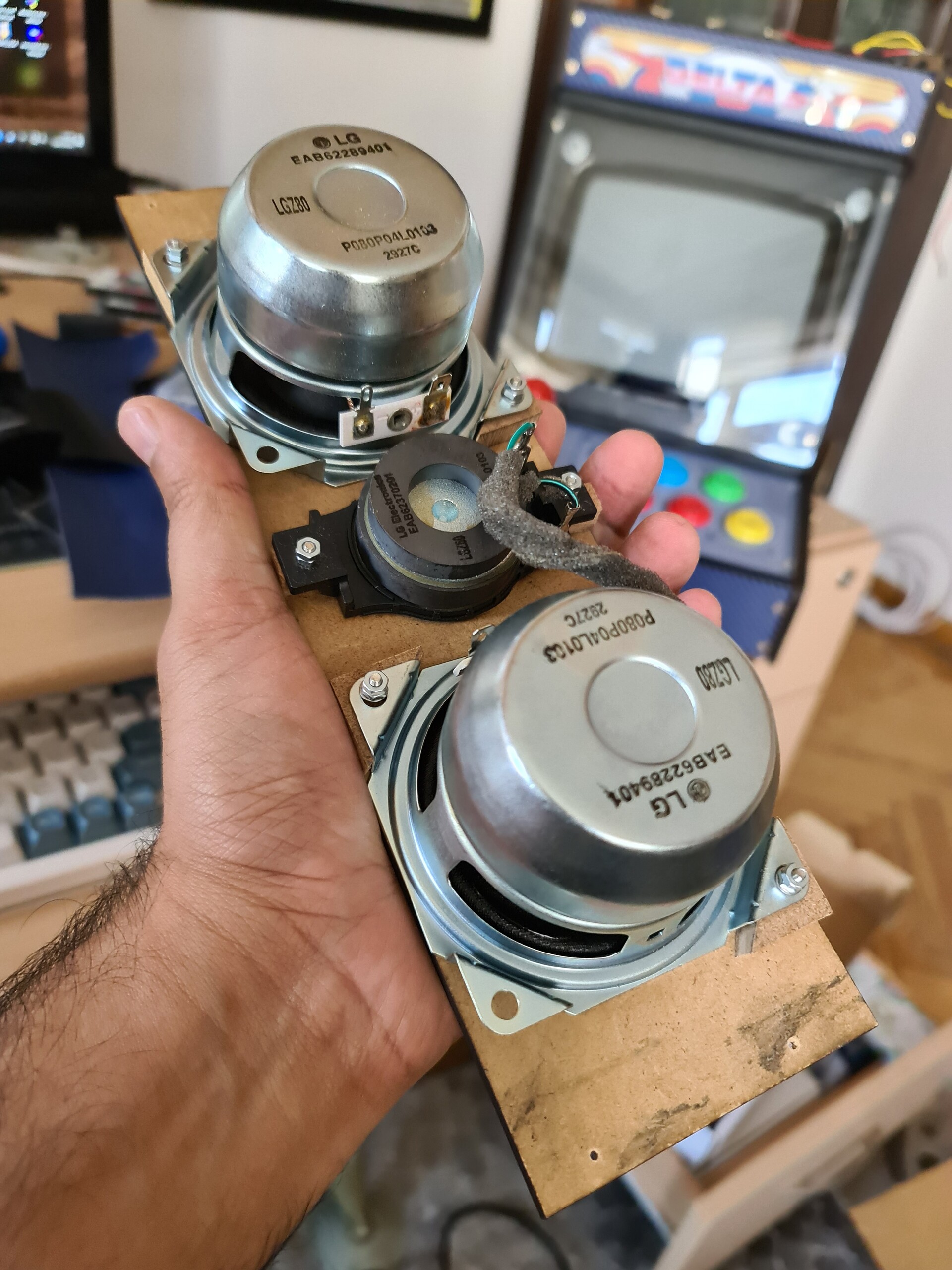
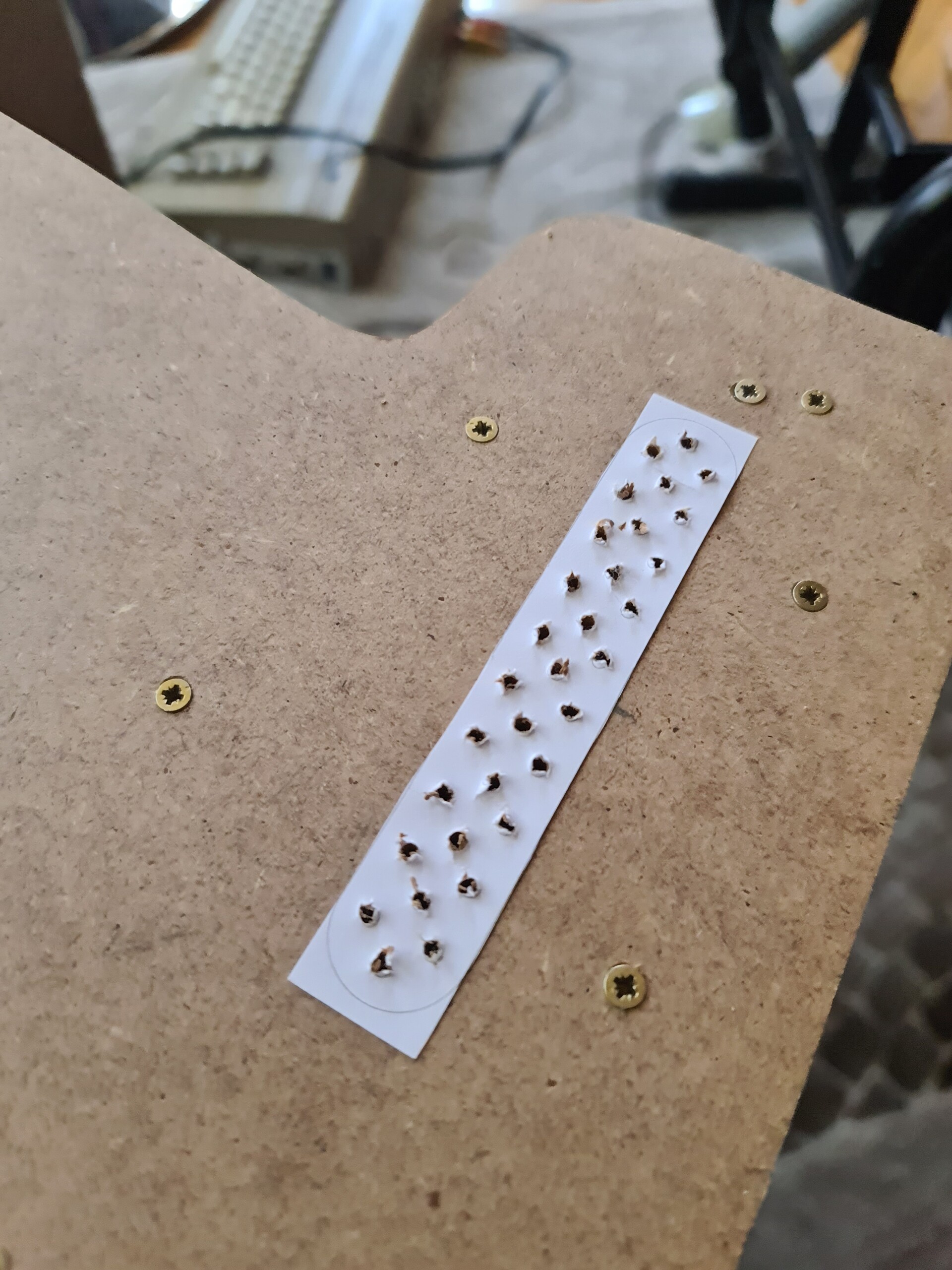
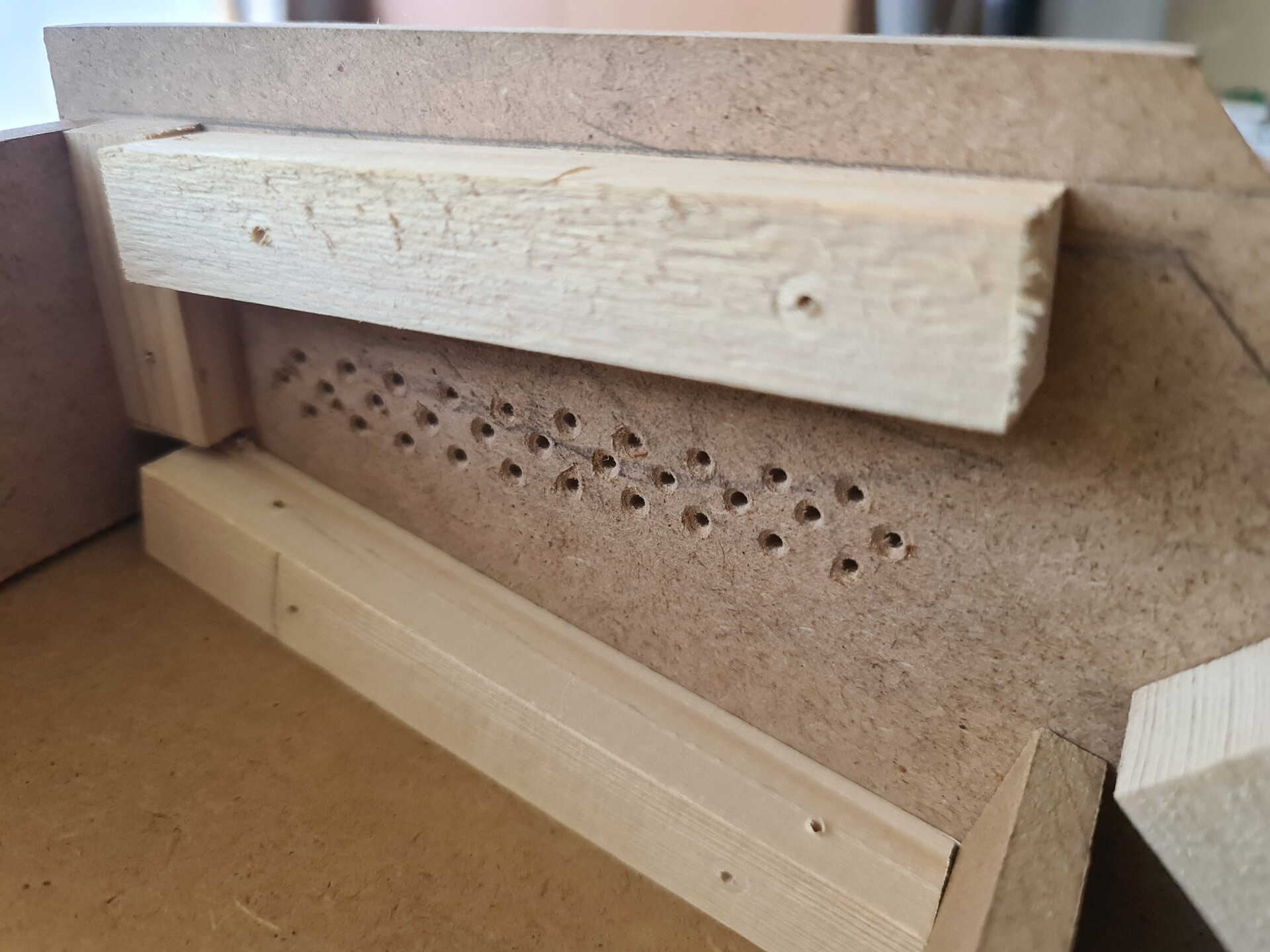
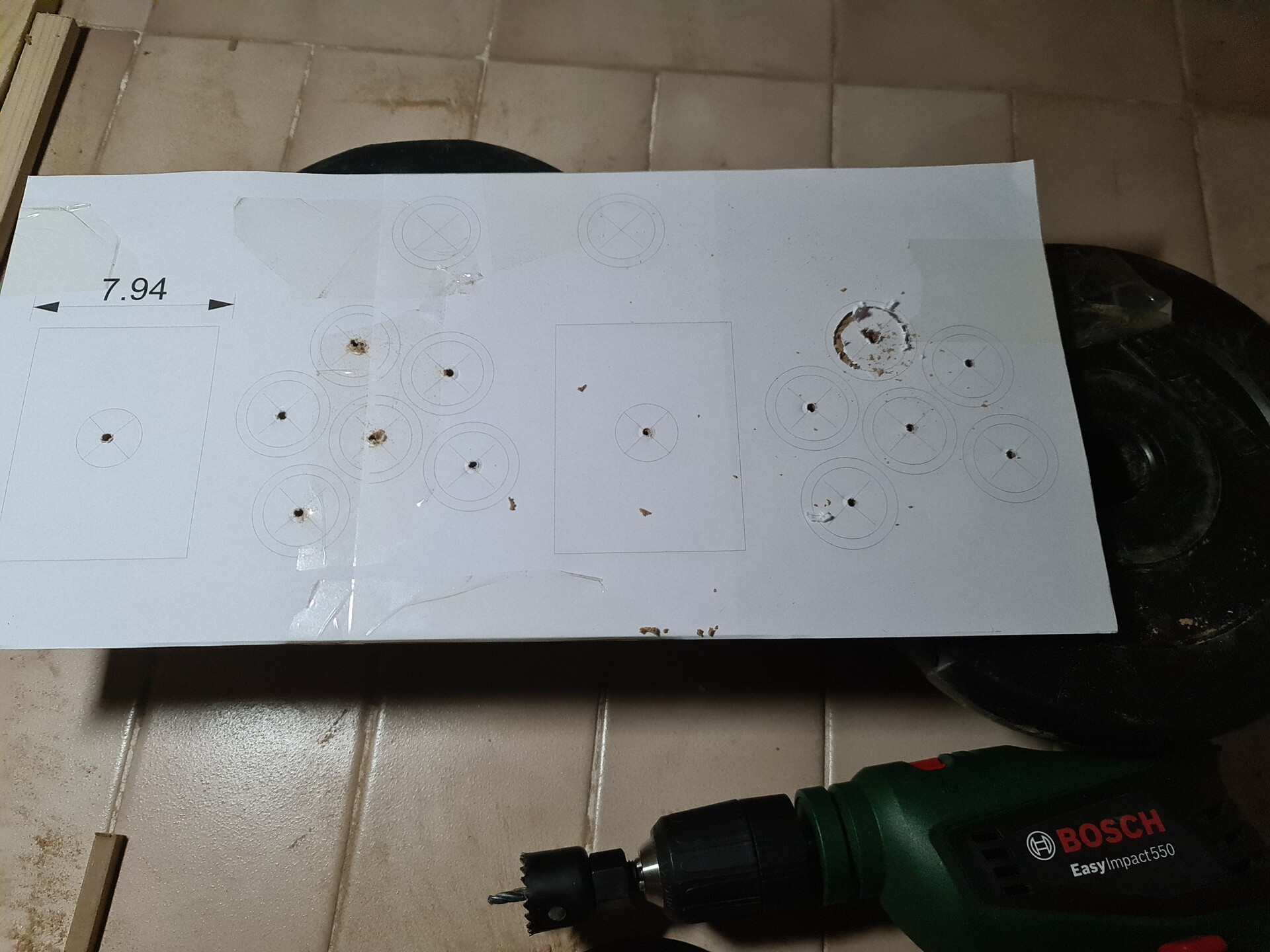
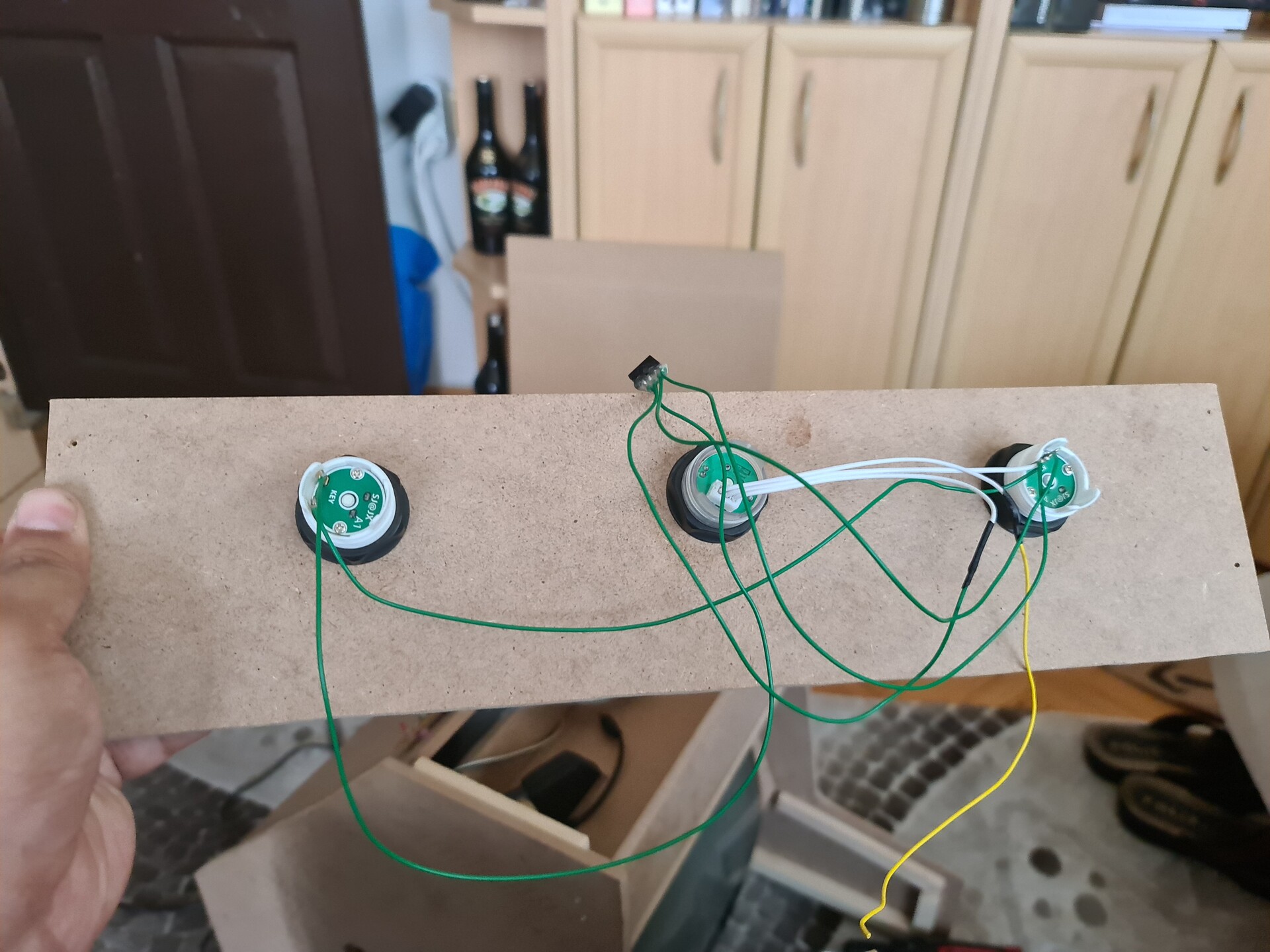
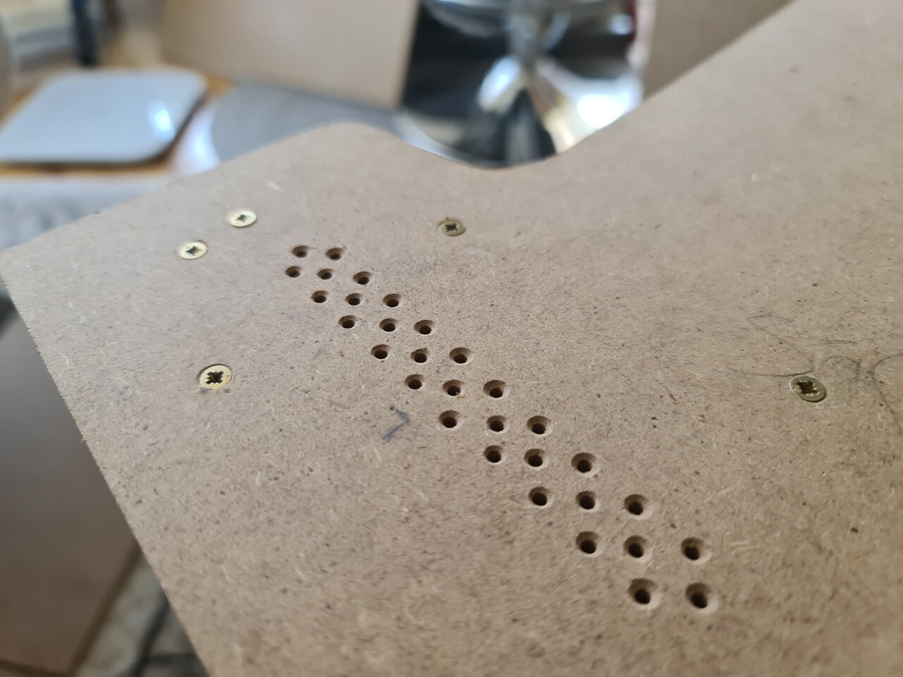
Next I placed the speakers of the TV to the side boards. And drilled holes for the sound to be not muffed. For drilling pattern, I created a quick placement and printed it to use as a template.

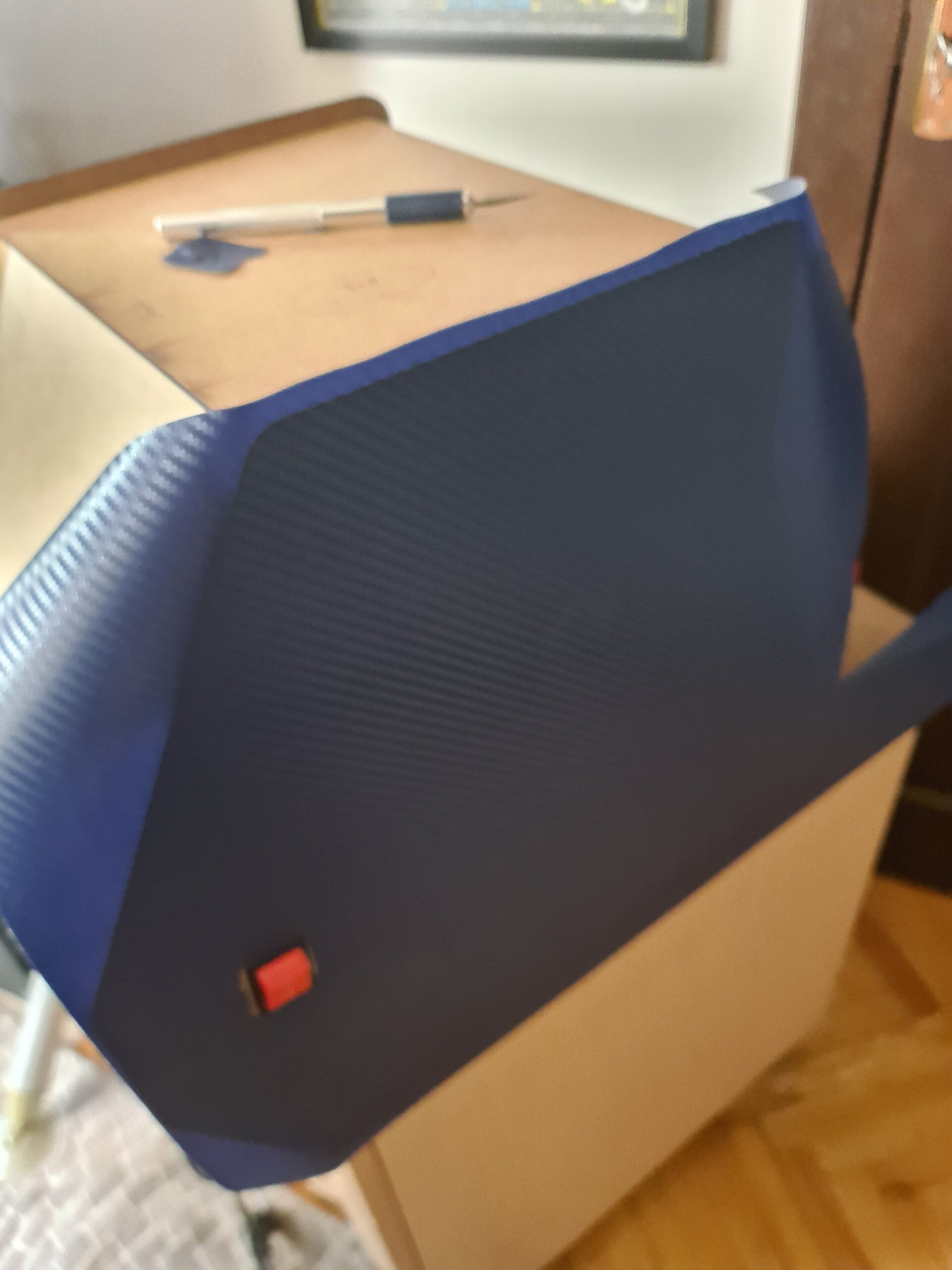
I used the same hole chamfering tool to make the holes look better. It was an unnecessary approach since I will cover that surface (including holes) with a stgicker folio.


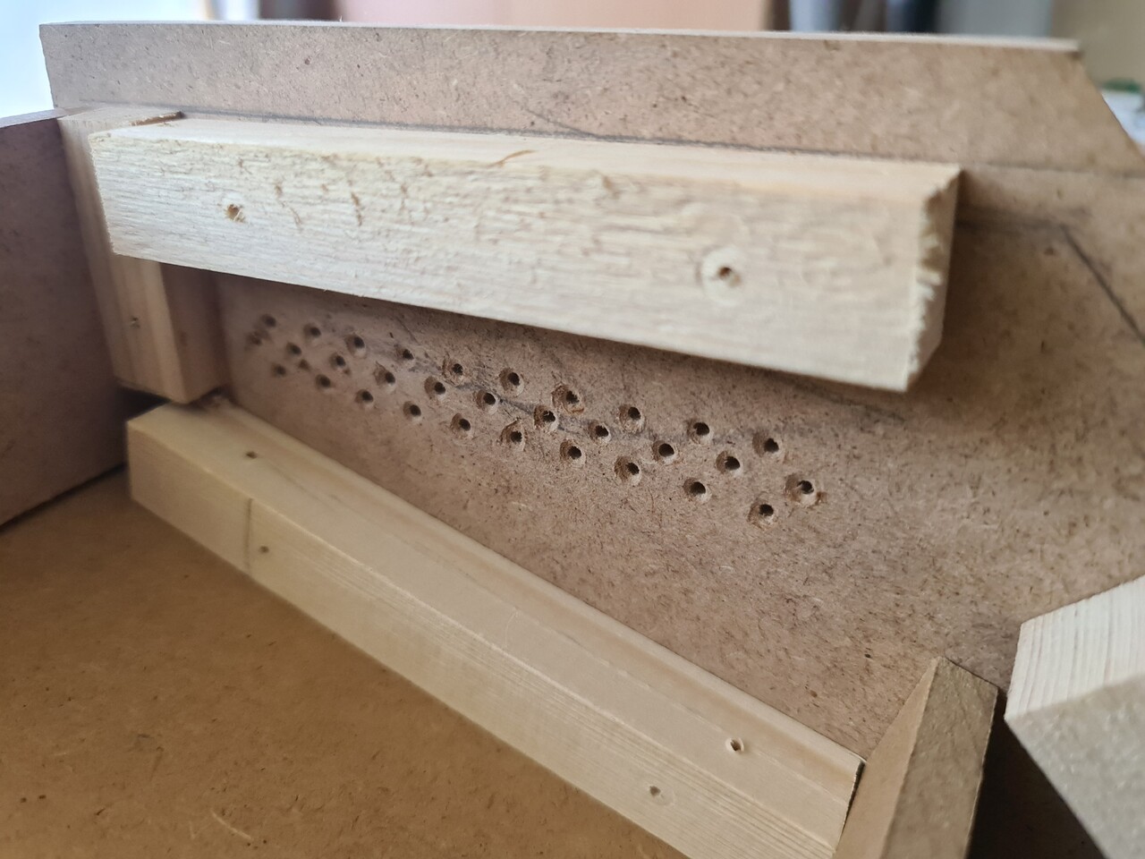
And finally connected the speakers back.

I positioned the scart cable to the top and connected my jamma to scart assembly to that cable. 

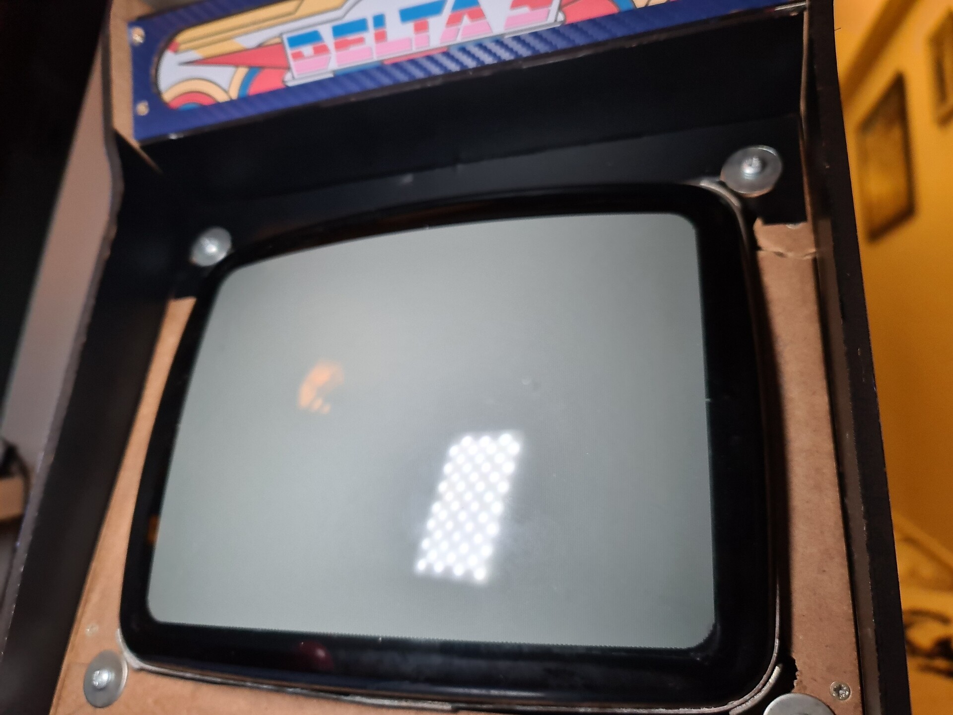
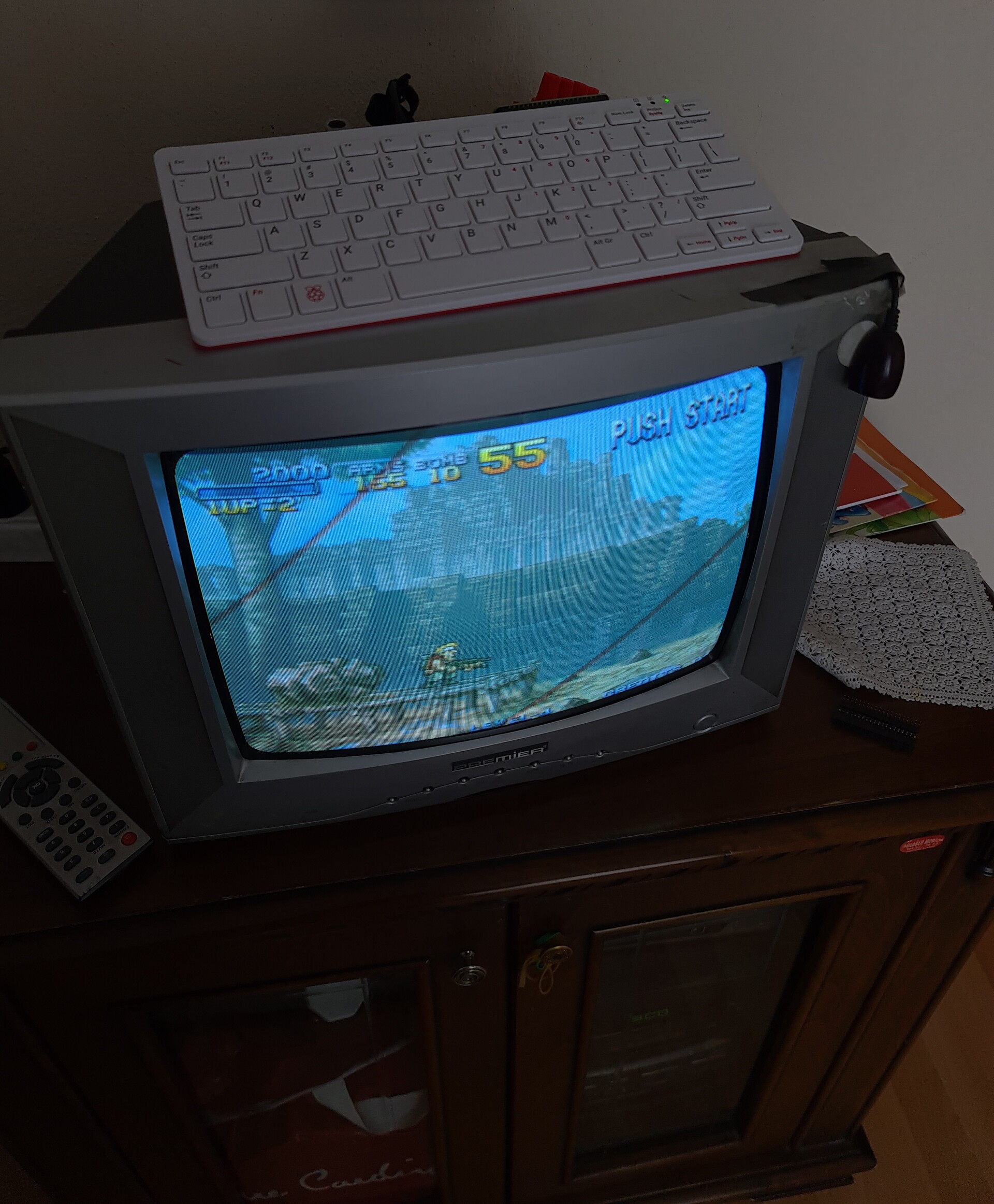
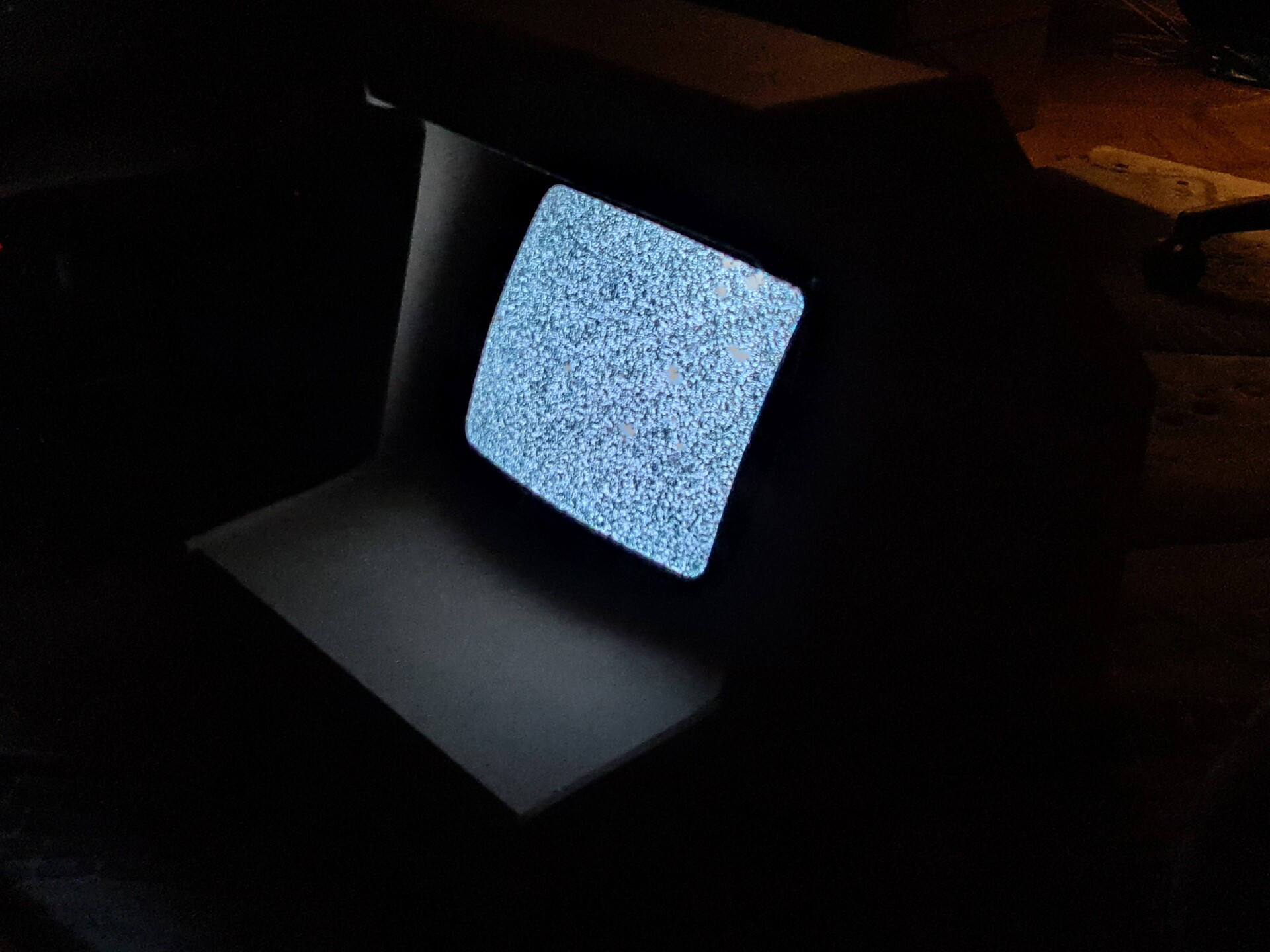
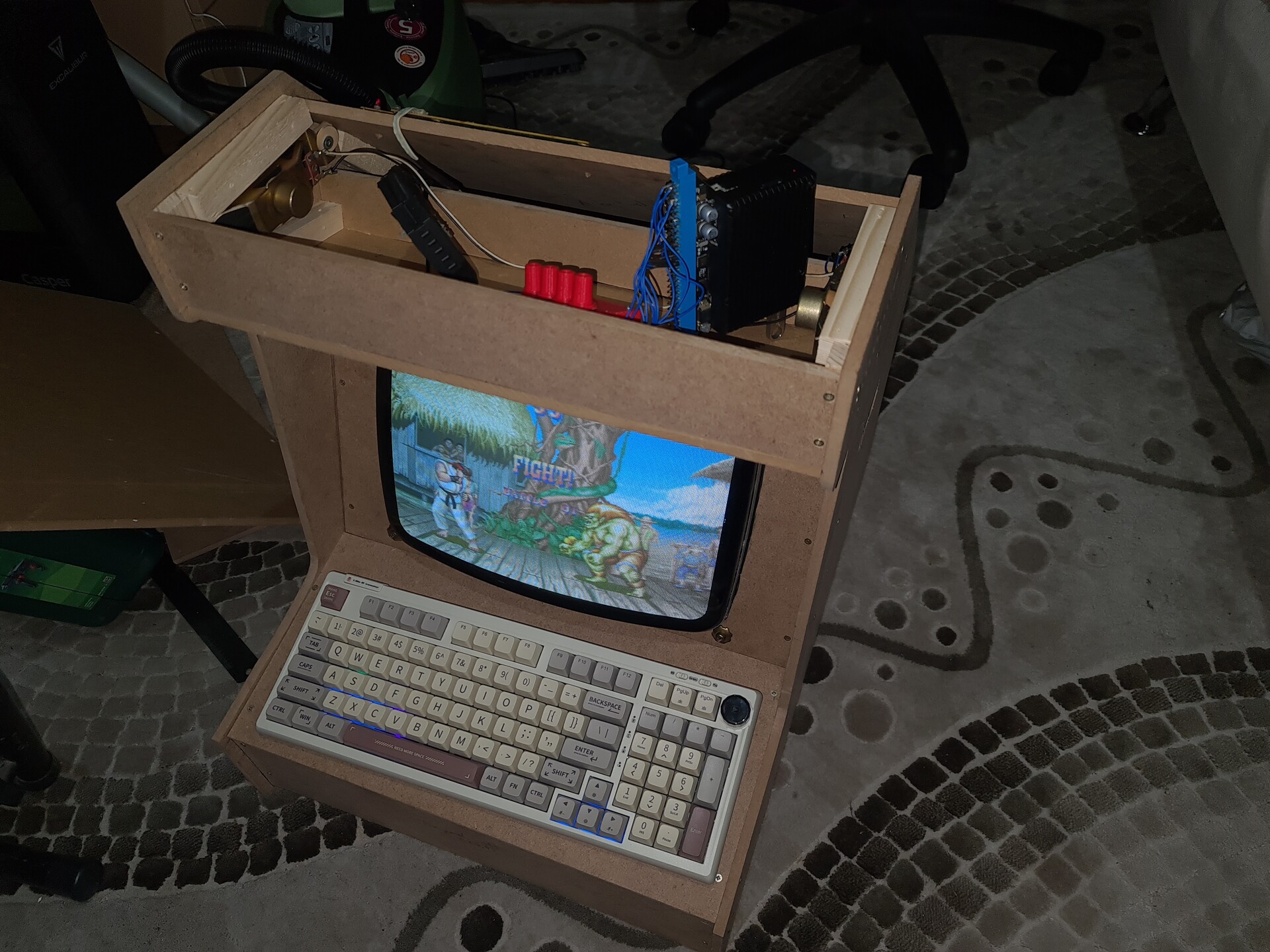
Testing the system and it's OK. That means I didn't broke anything with the TV while I'm mounting it to my cabinet. Using my fancy keyboard on bluetooth since I have no controller installed yet.

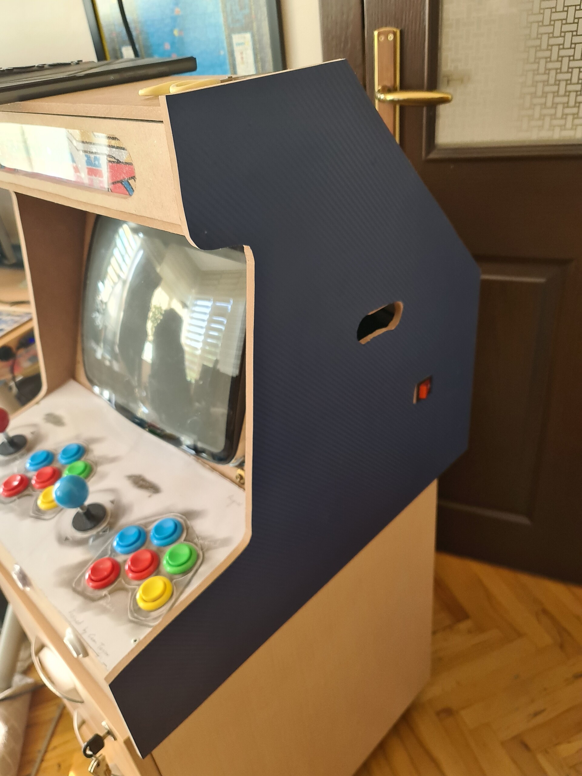
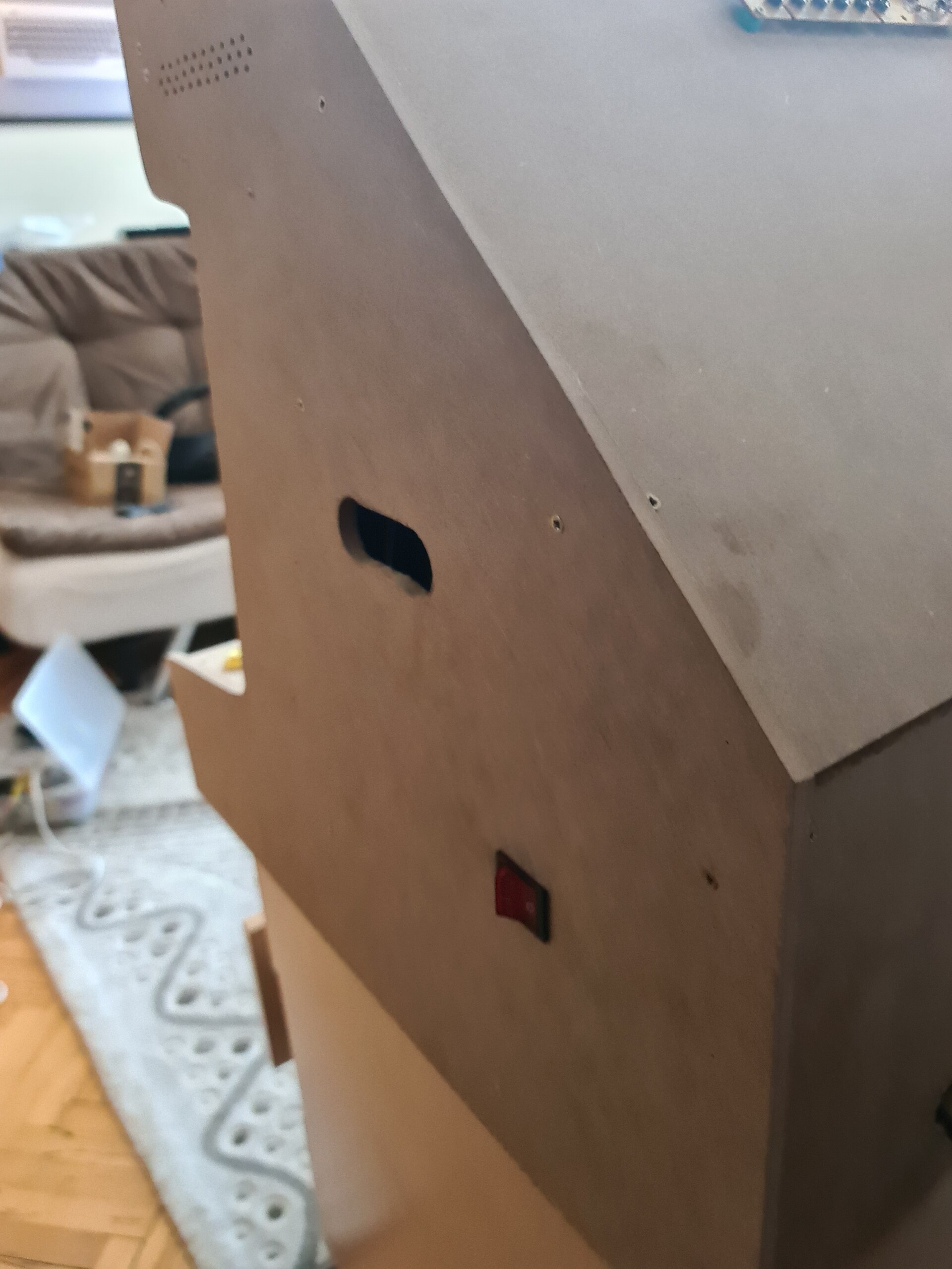
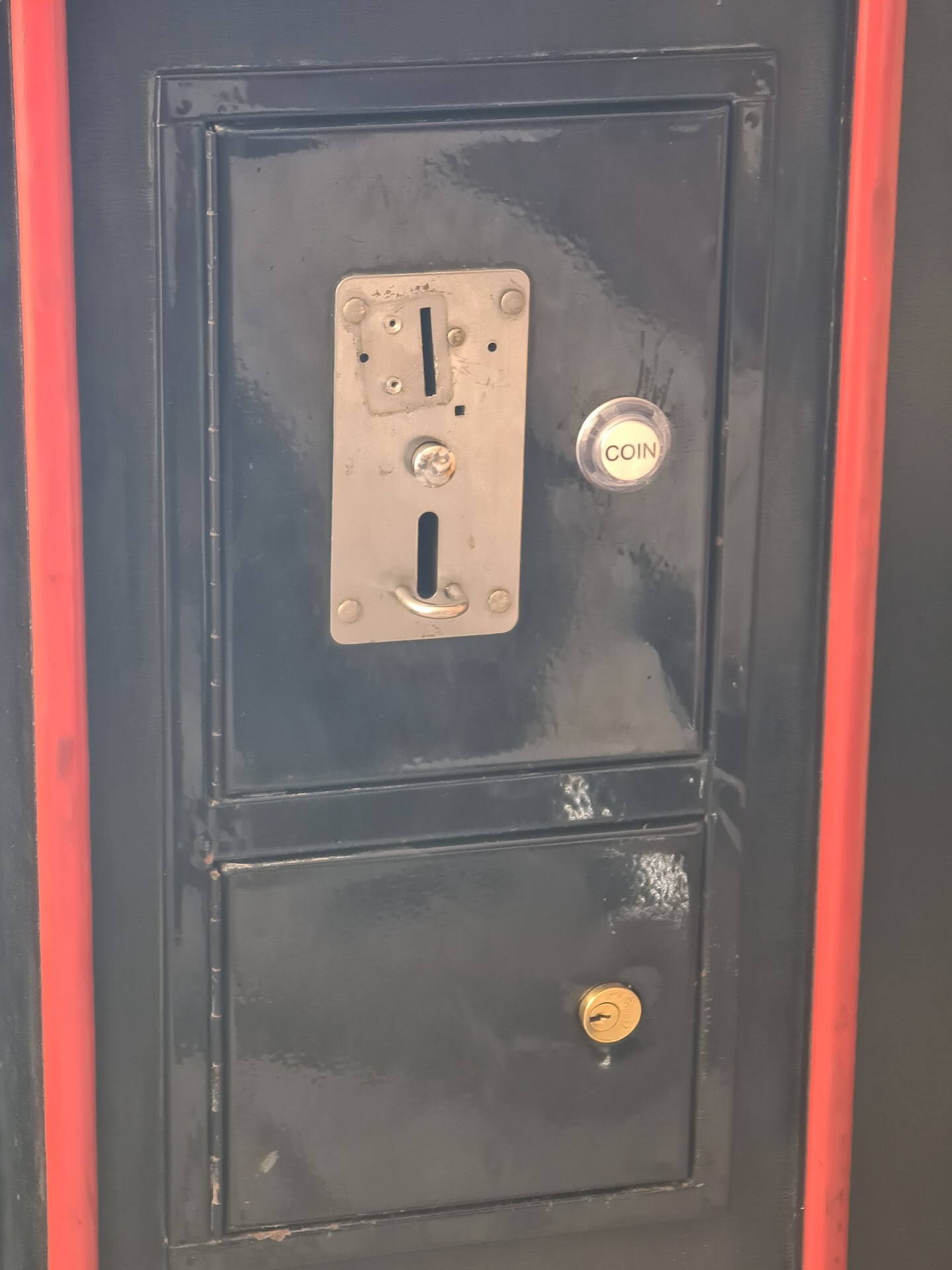
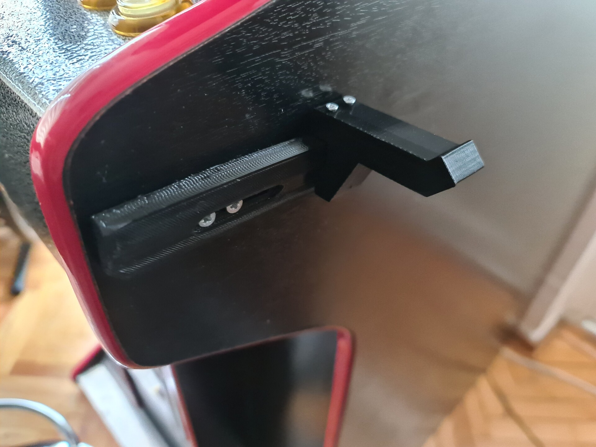
I added a slot hole to the both side for carrying the cabinet. I driled two big holes and connected two holes by a single saw. It's 17 kilograms so far. Can be carried easily by two people.

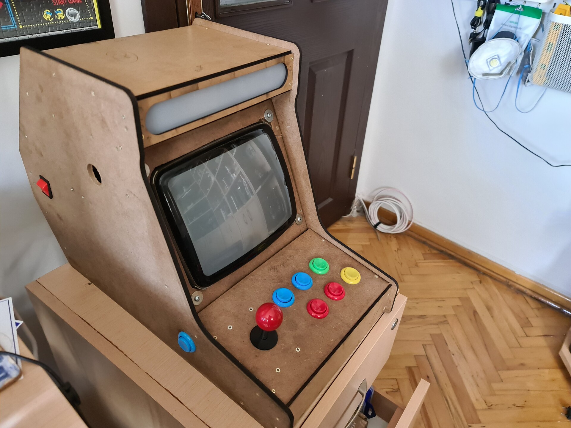
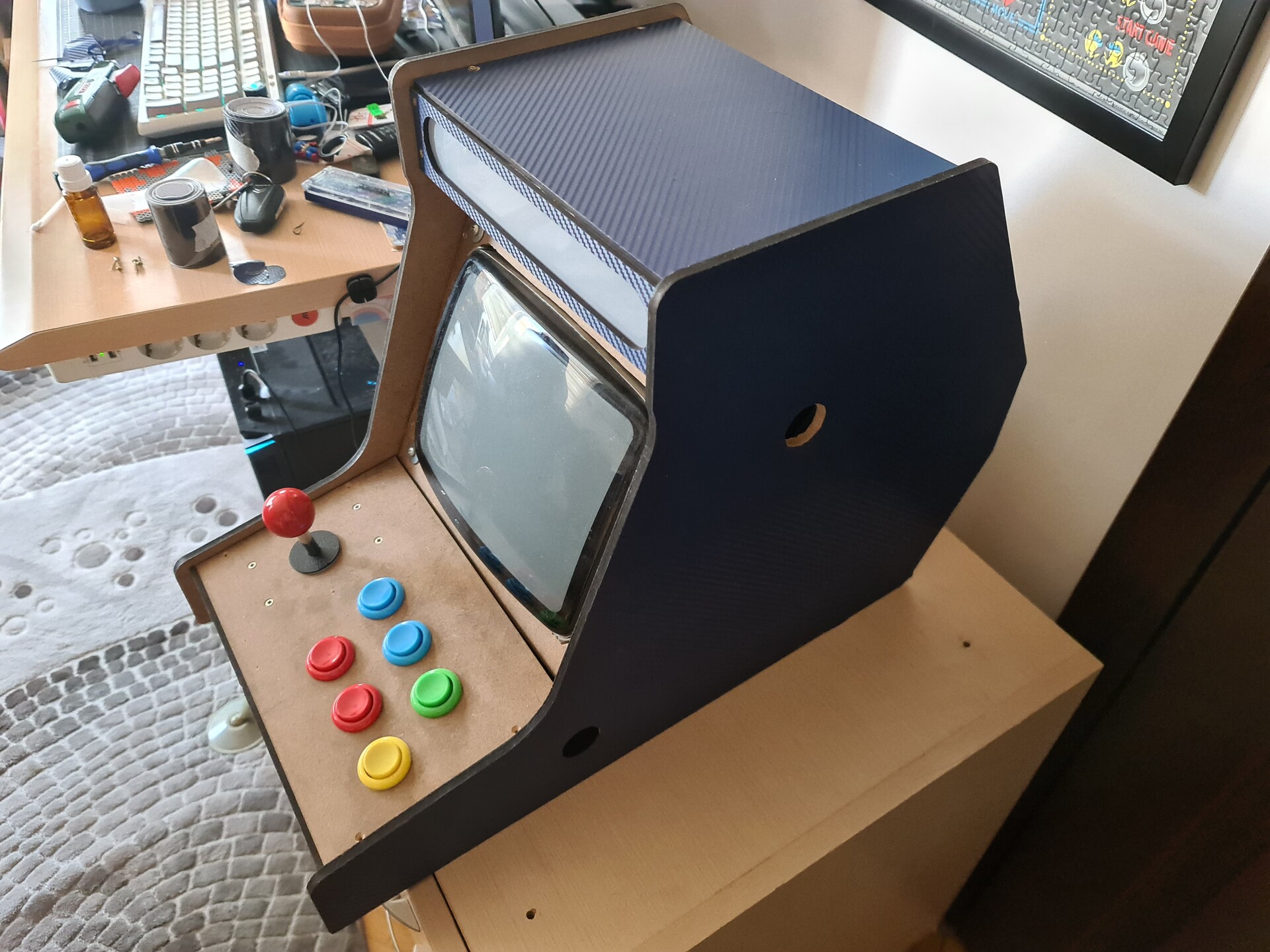
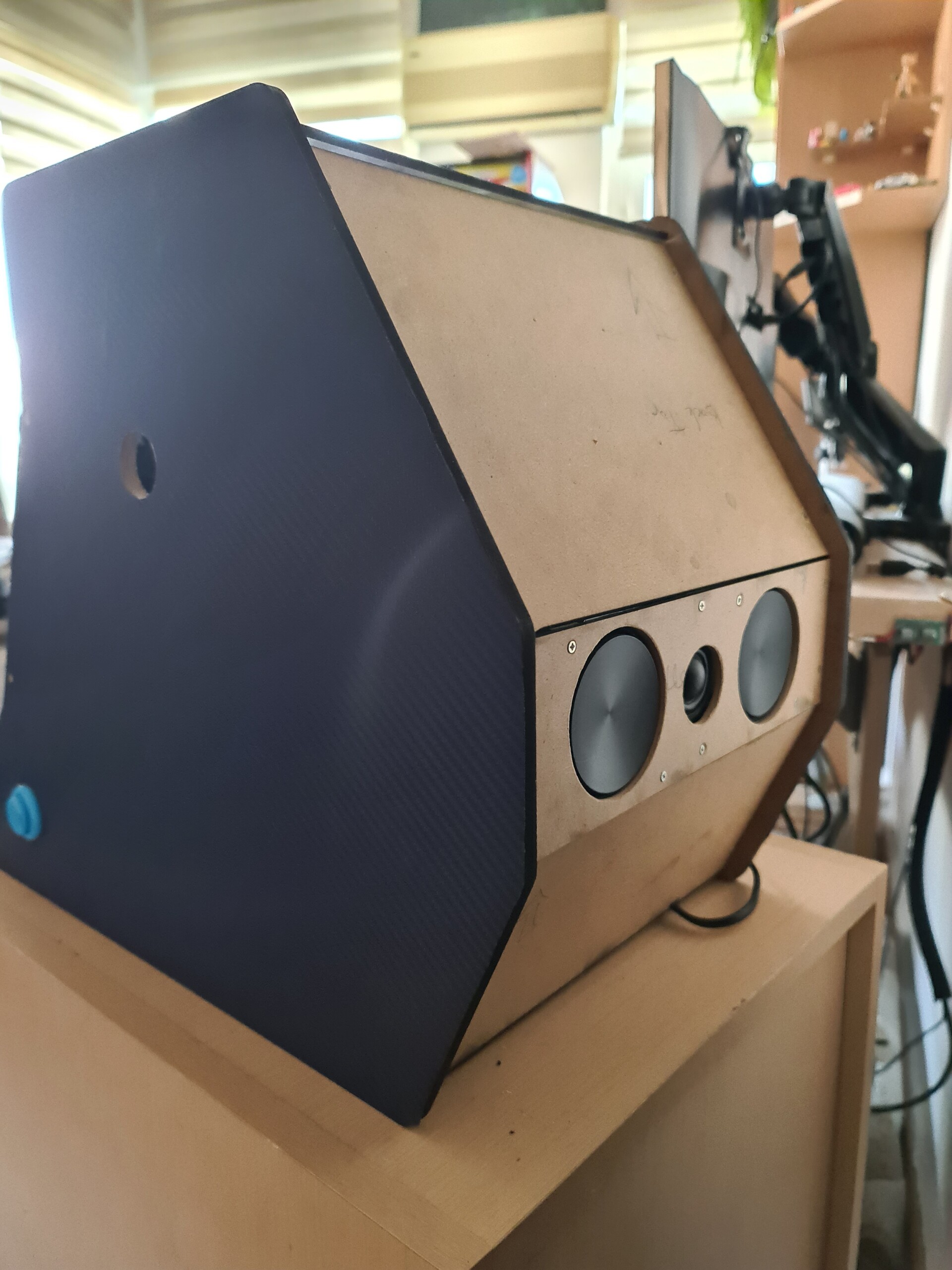
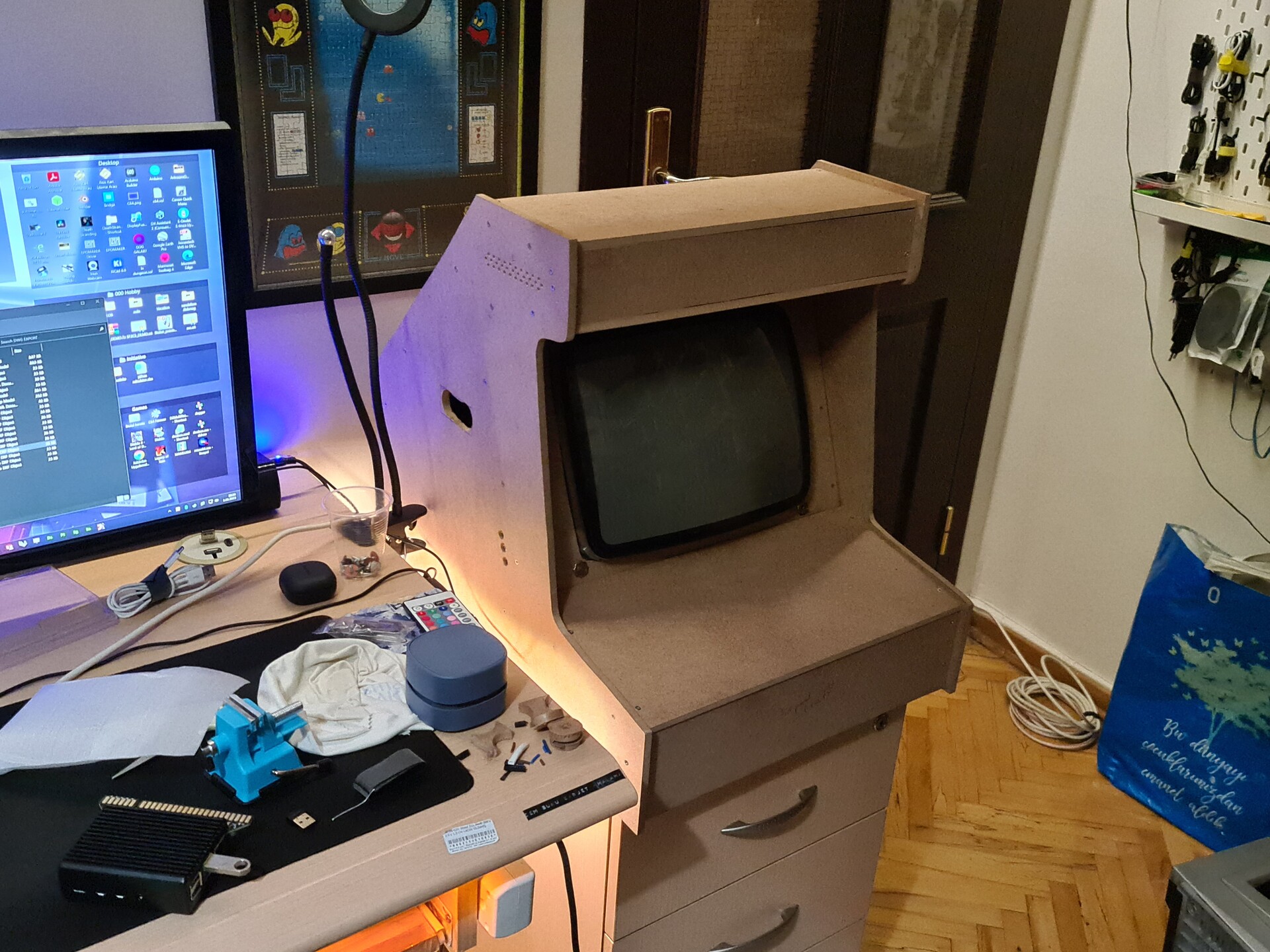
Shape is slowly forming. 

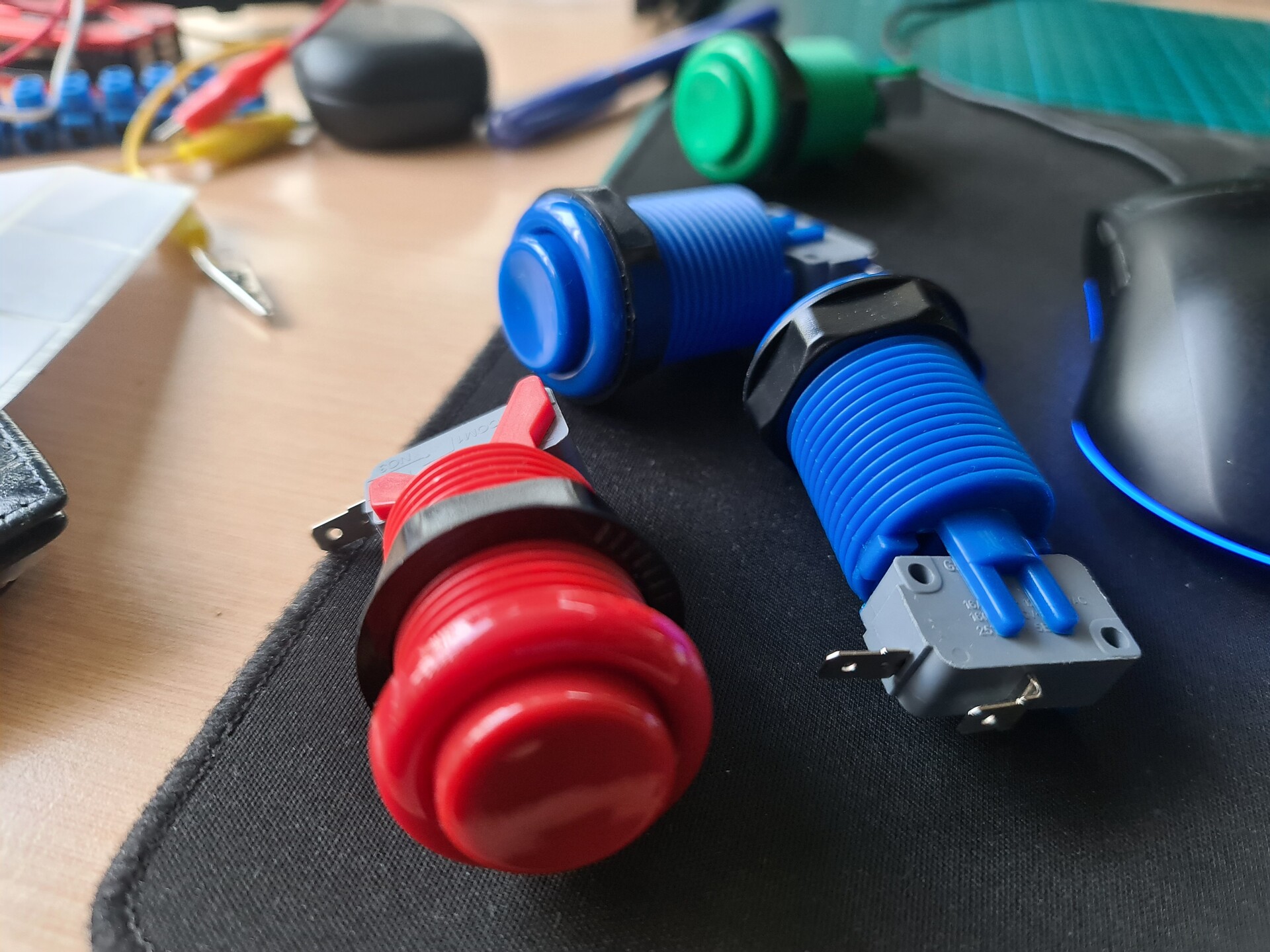
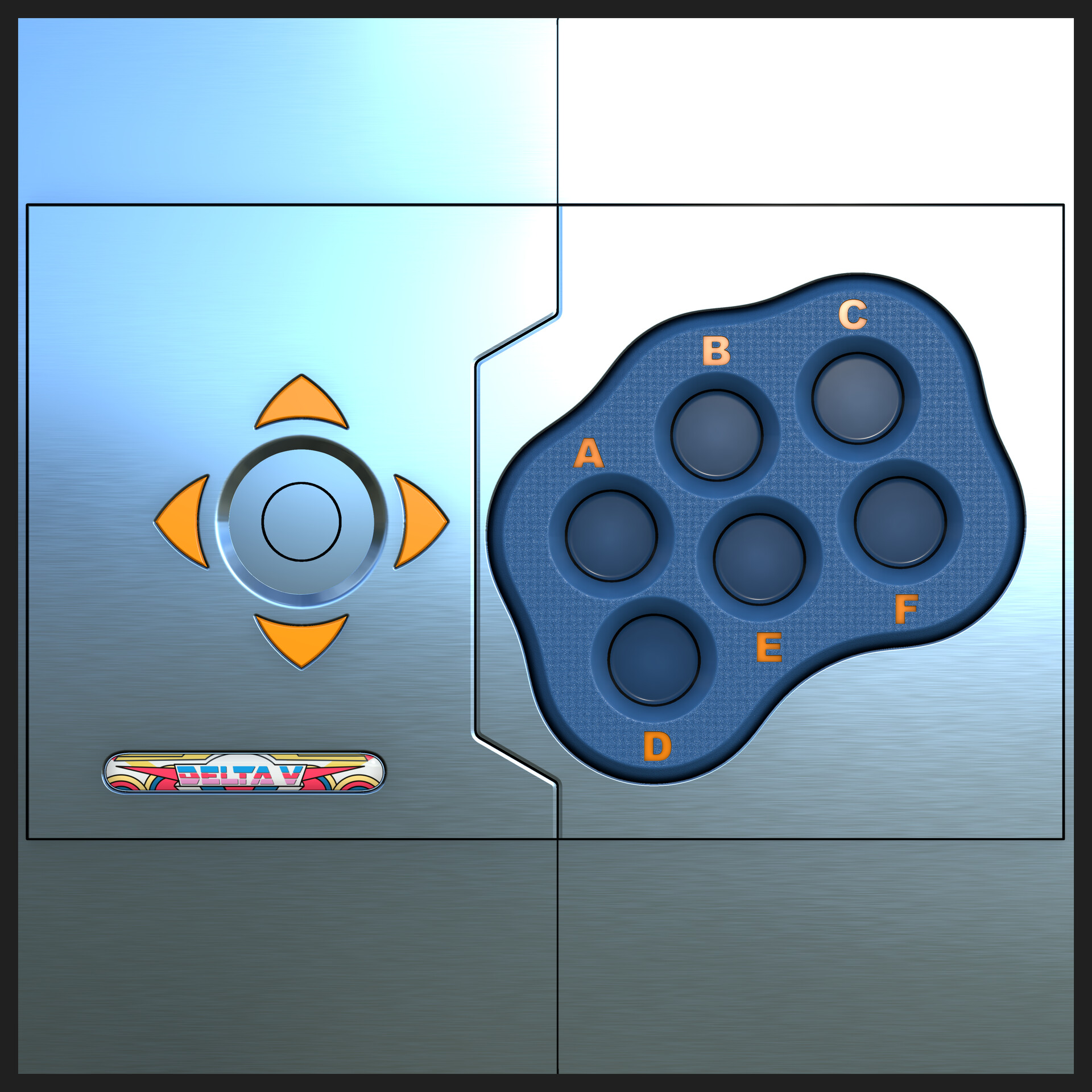
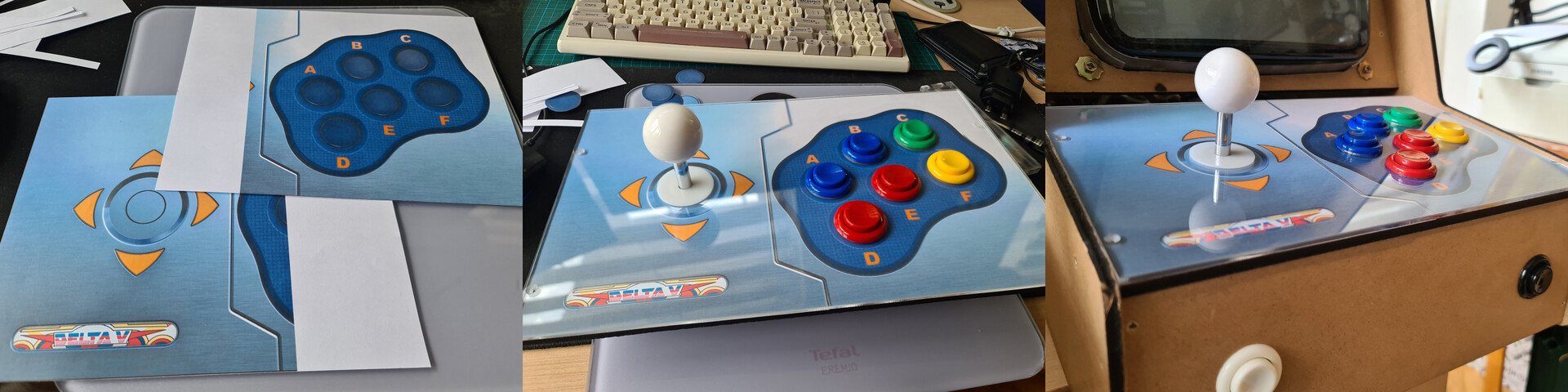
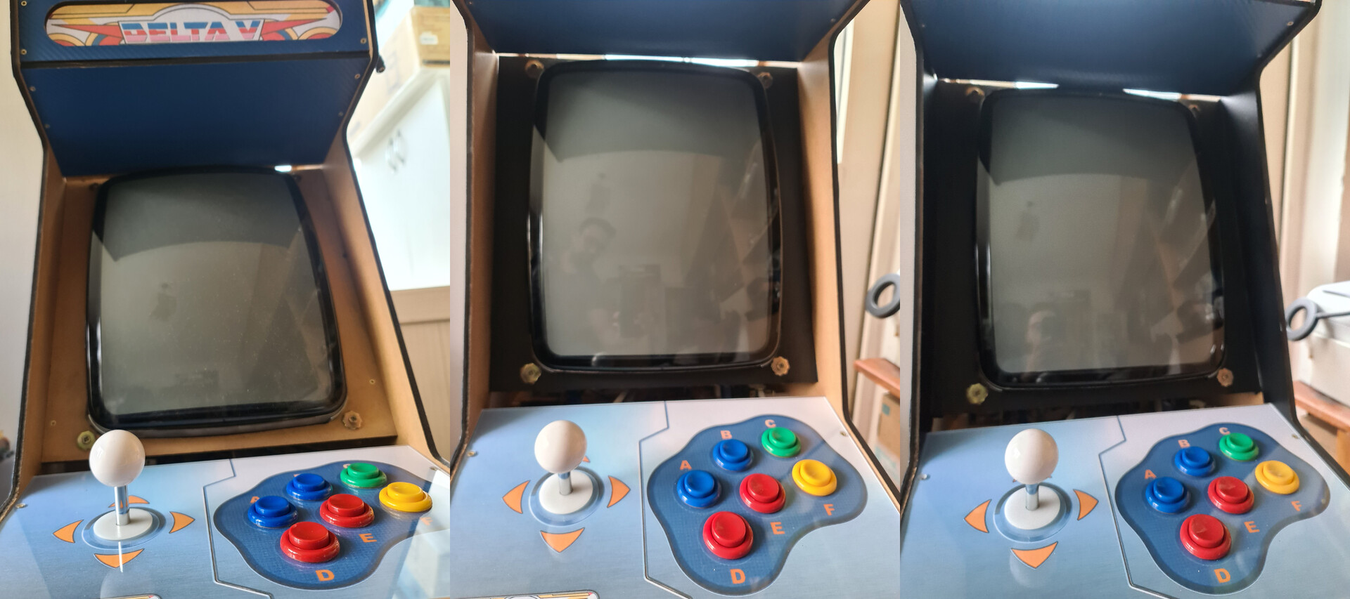
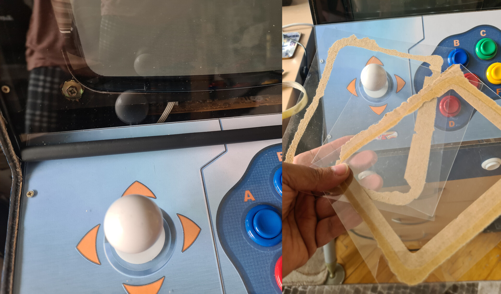
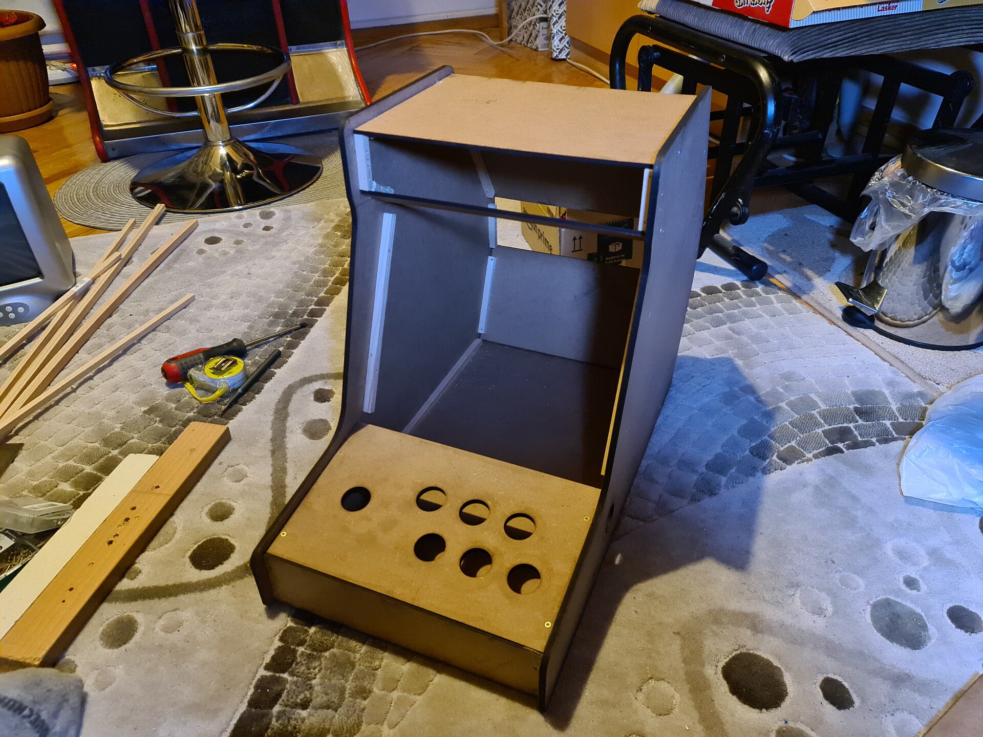
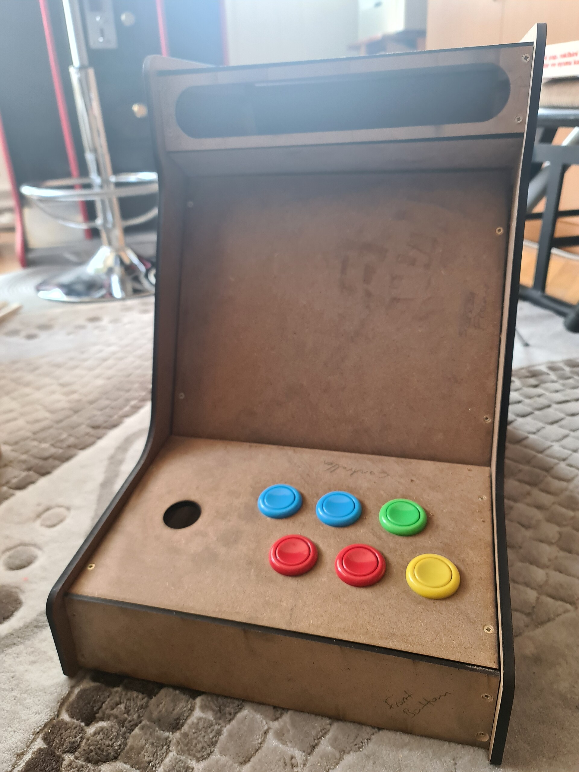
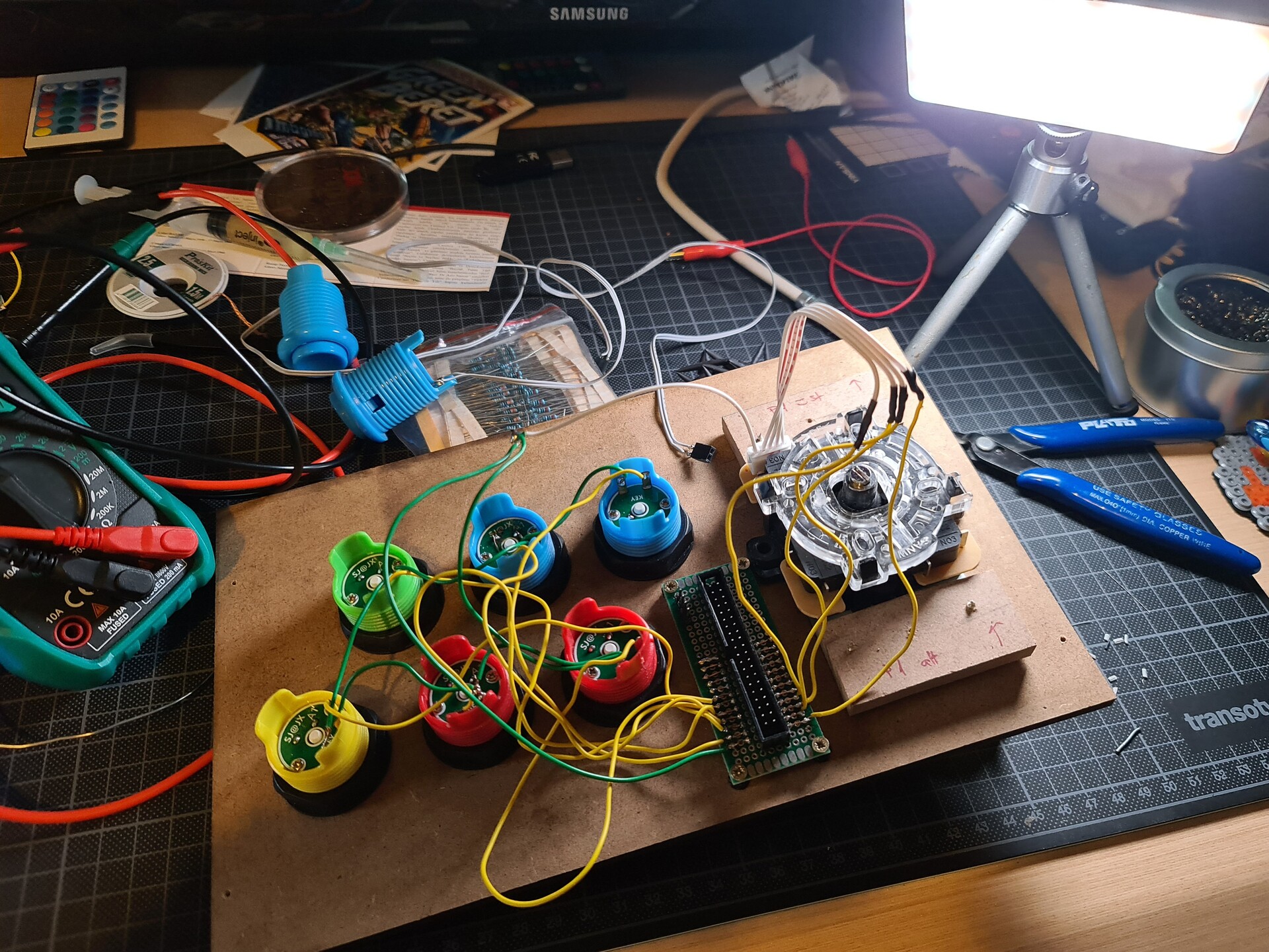
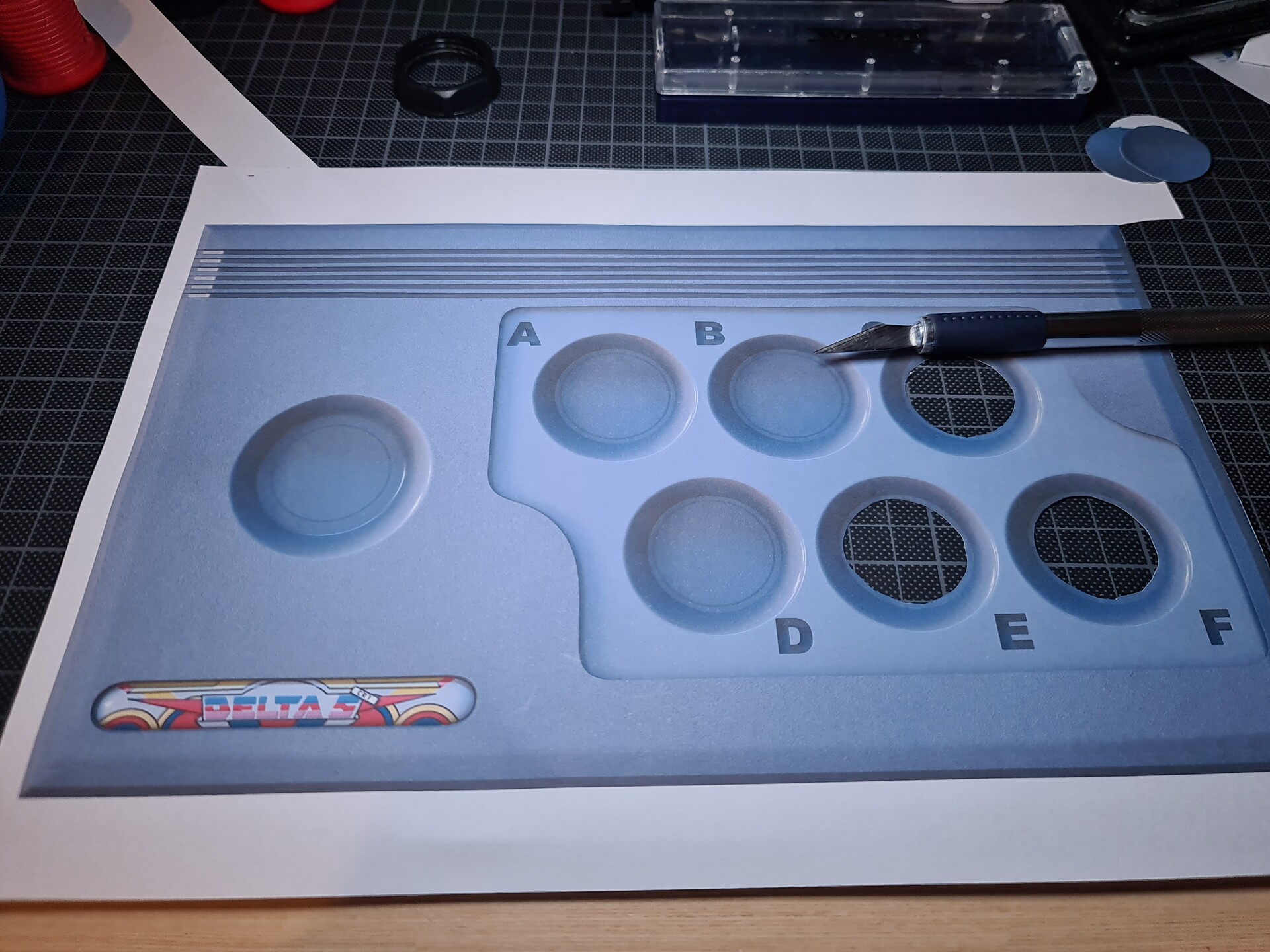
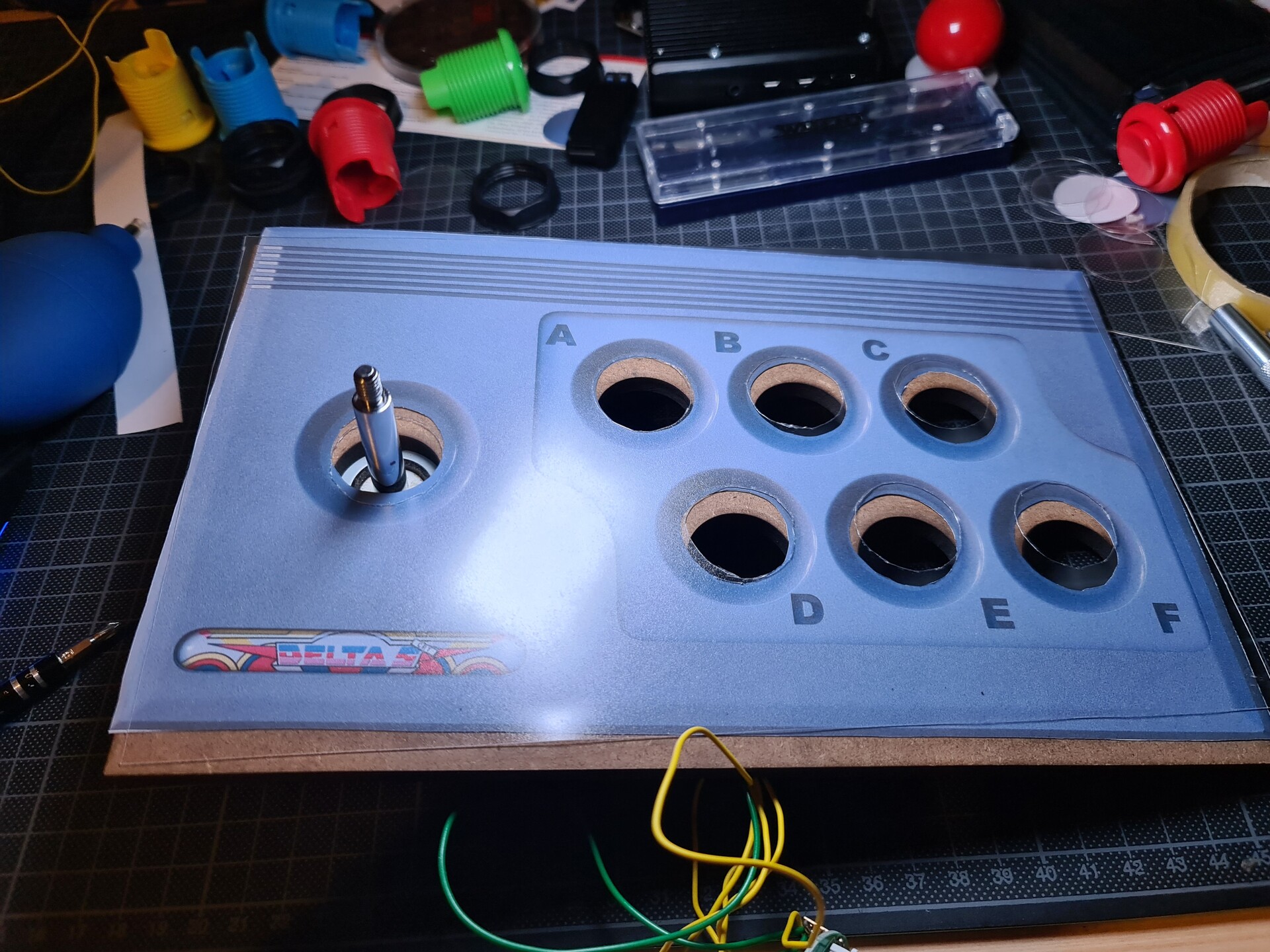
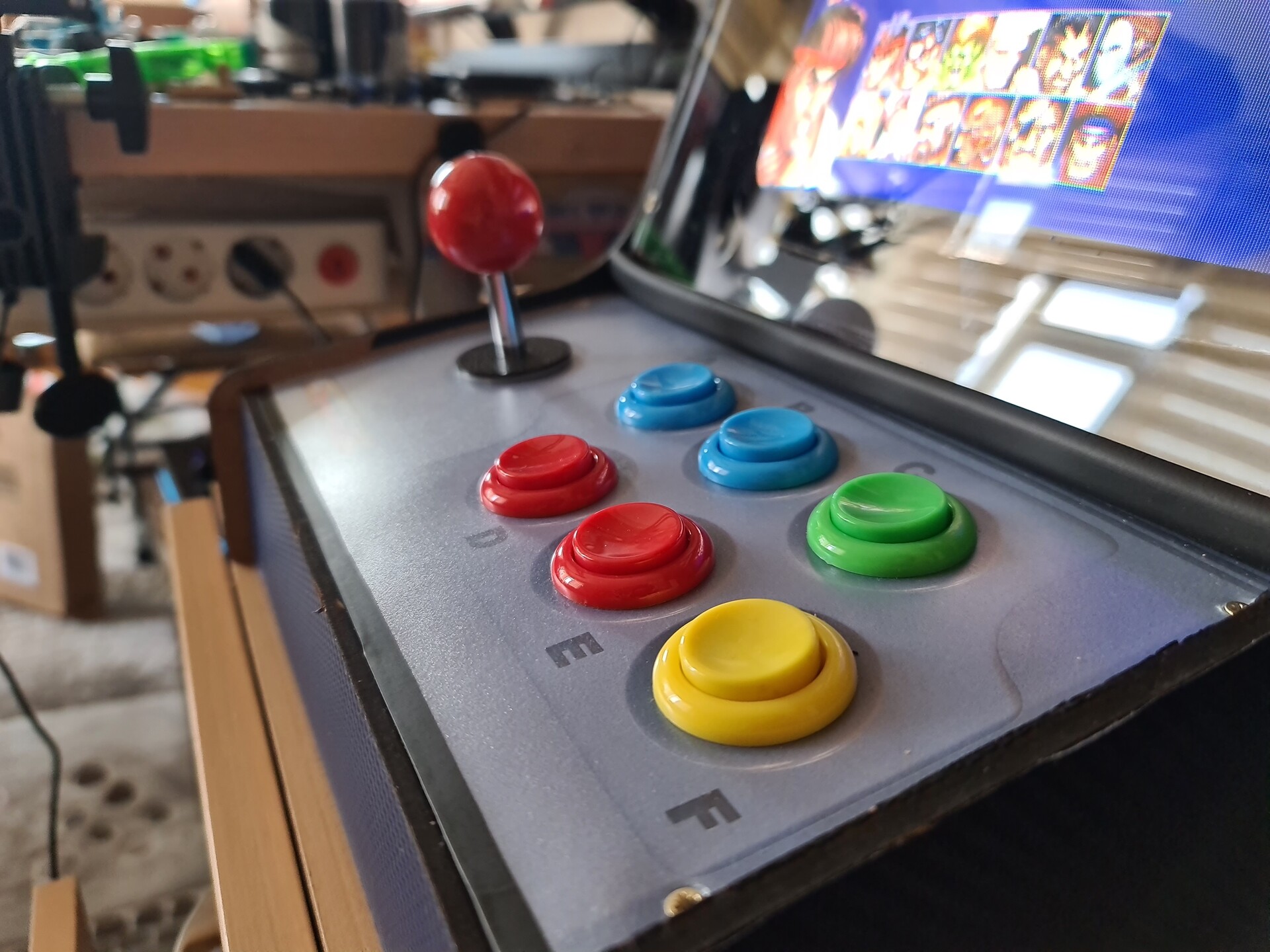
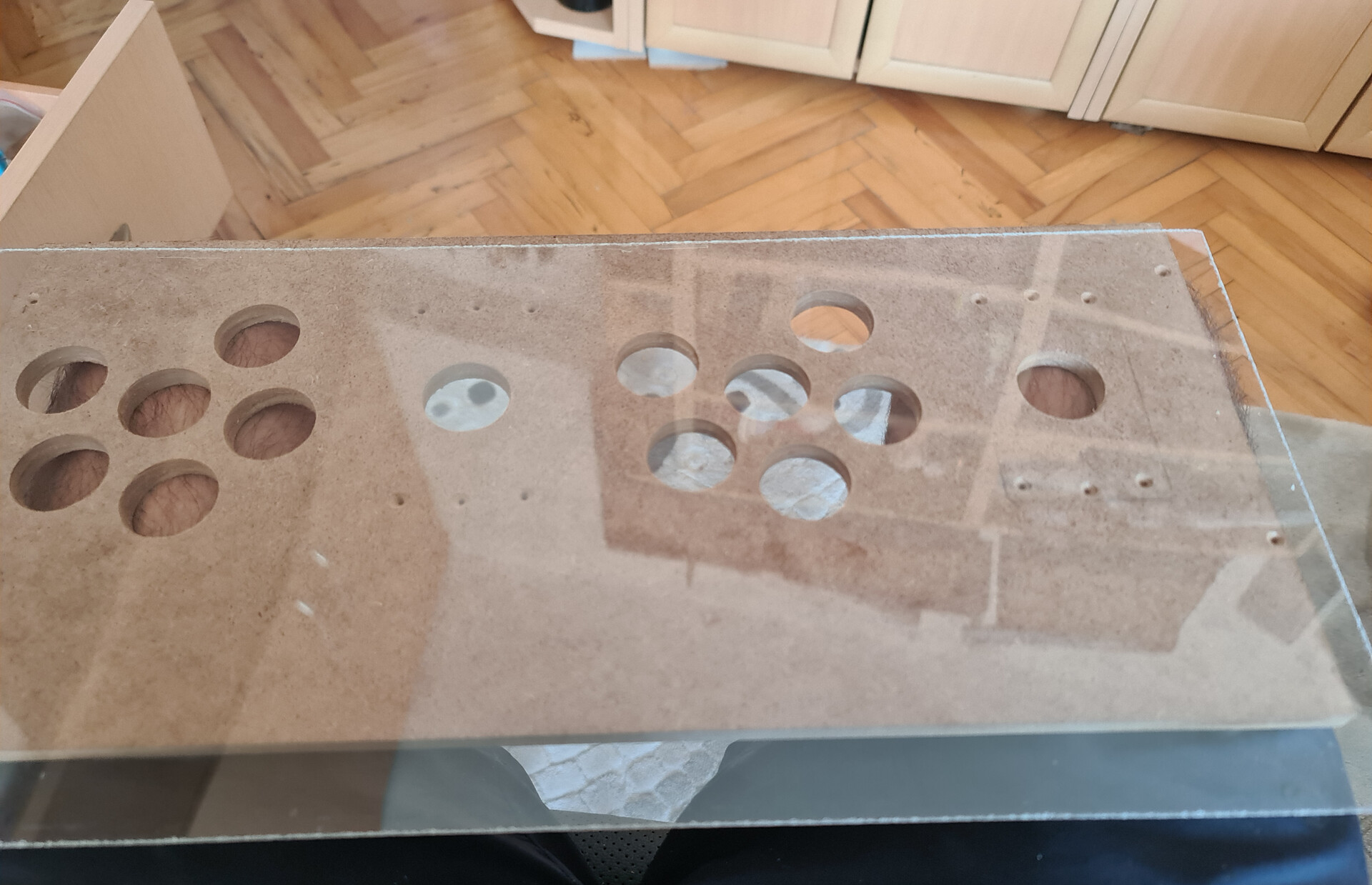
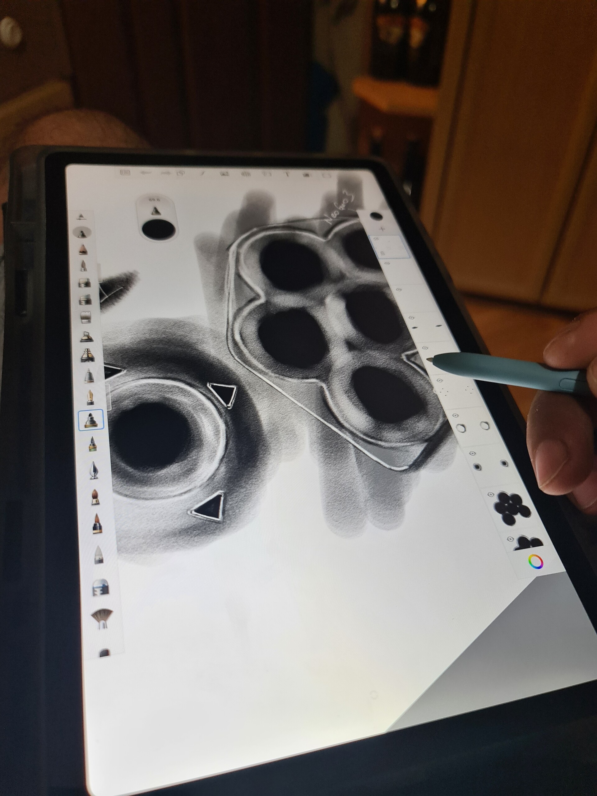
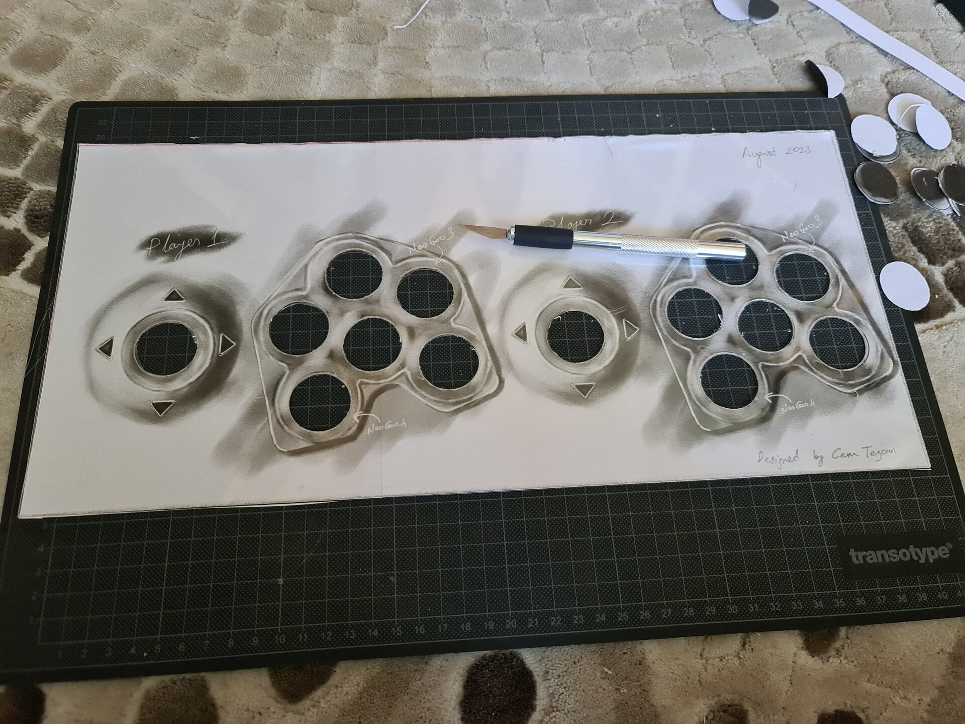
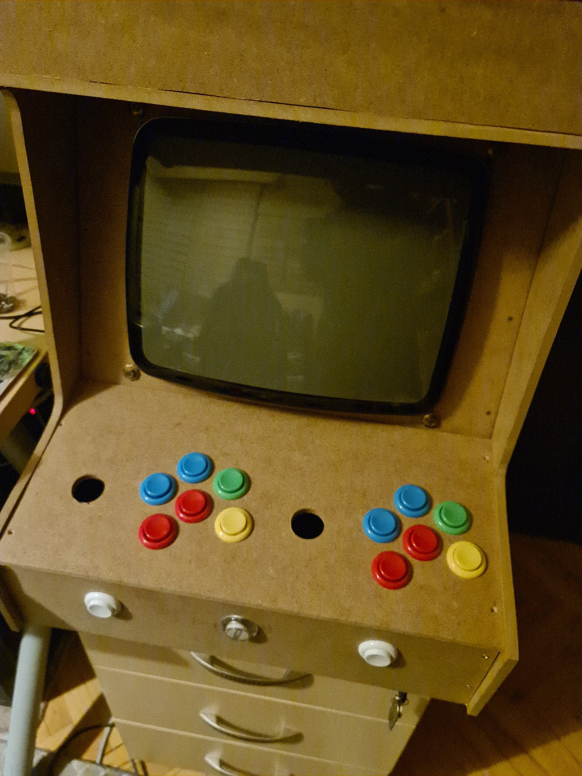
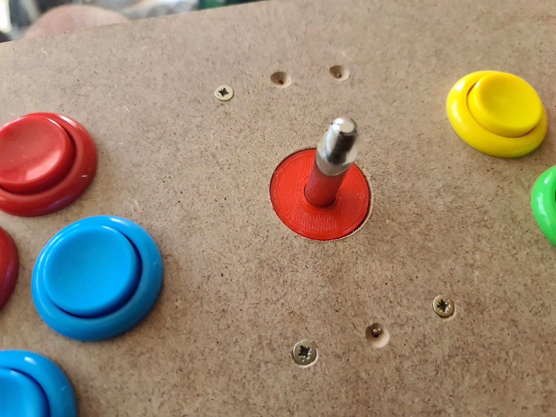
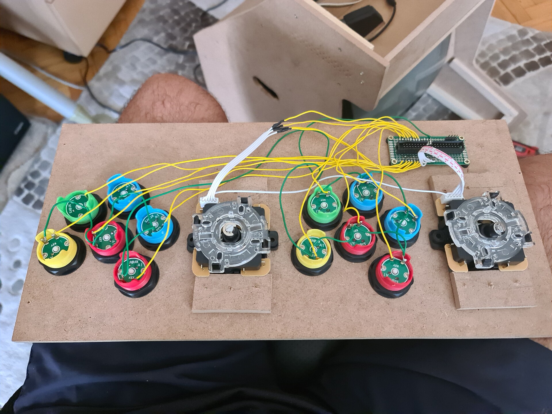
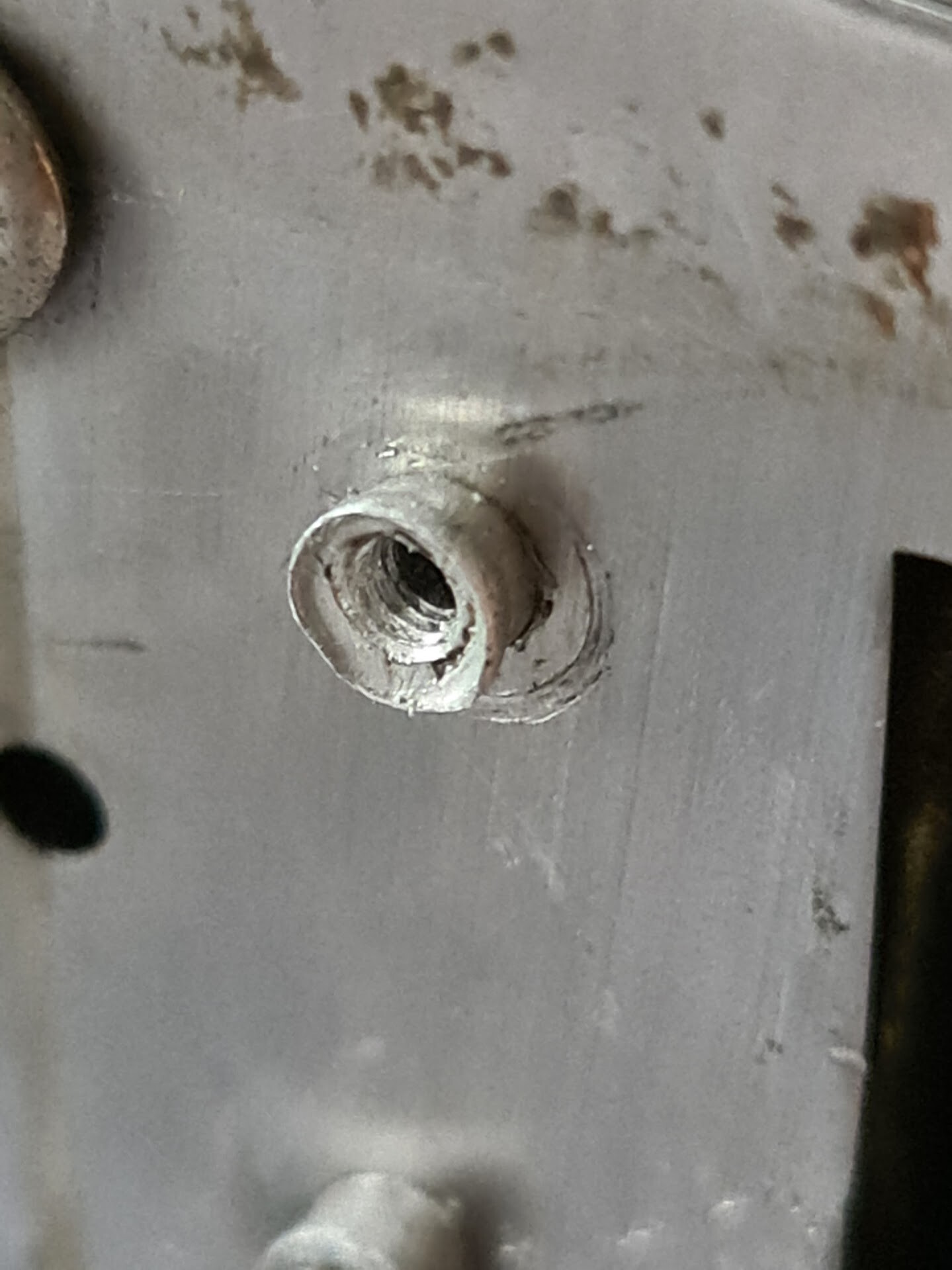
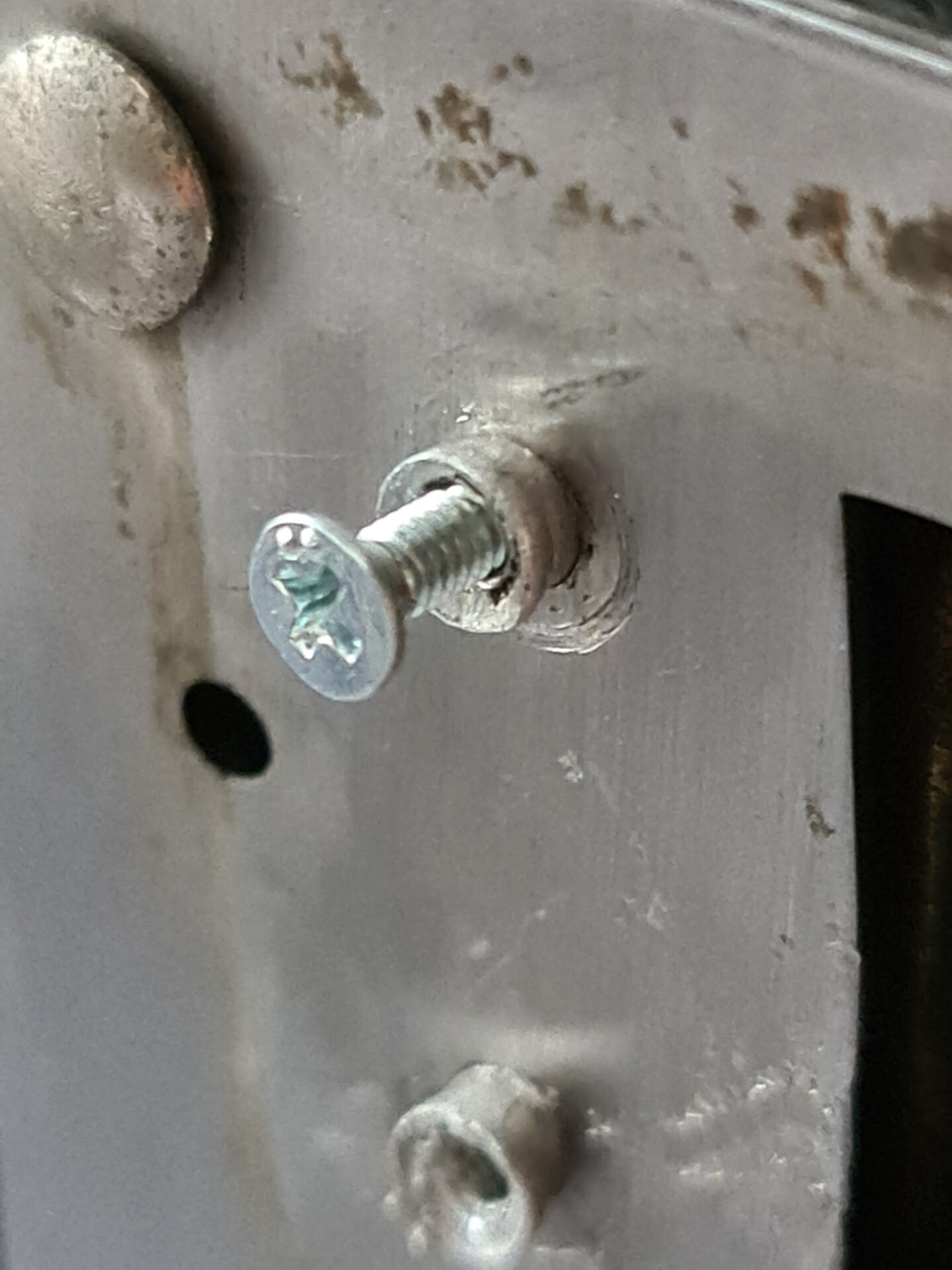
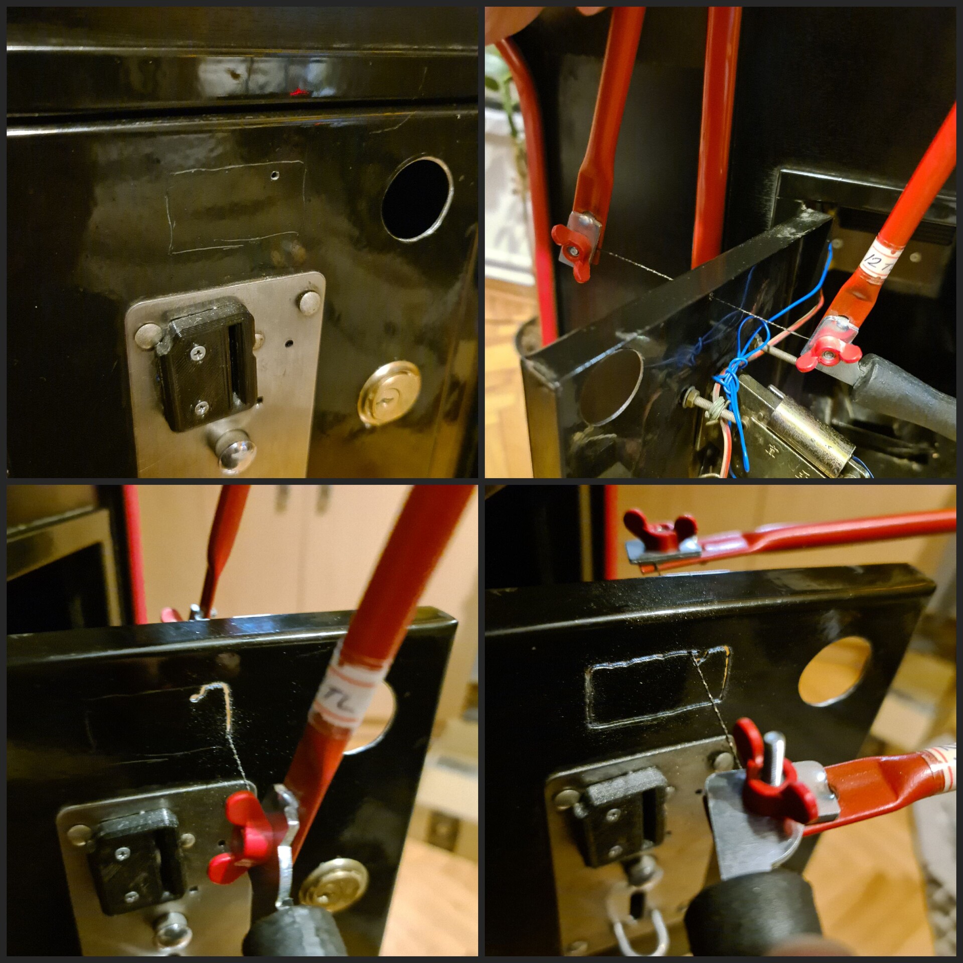
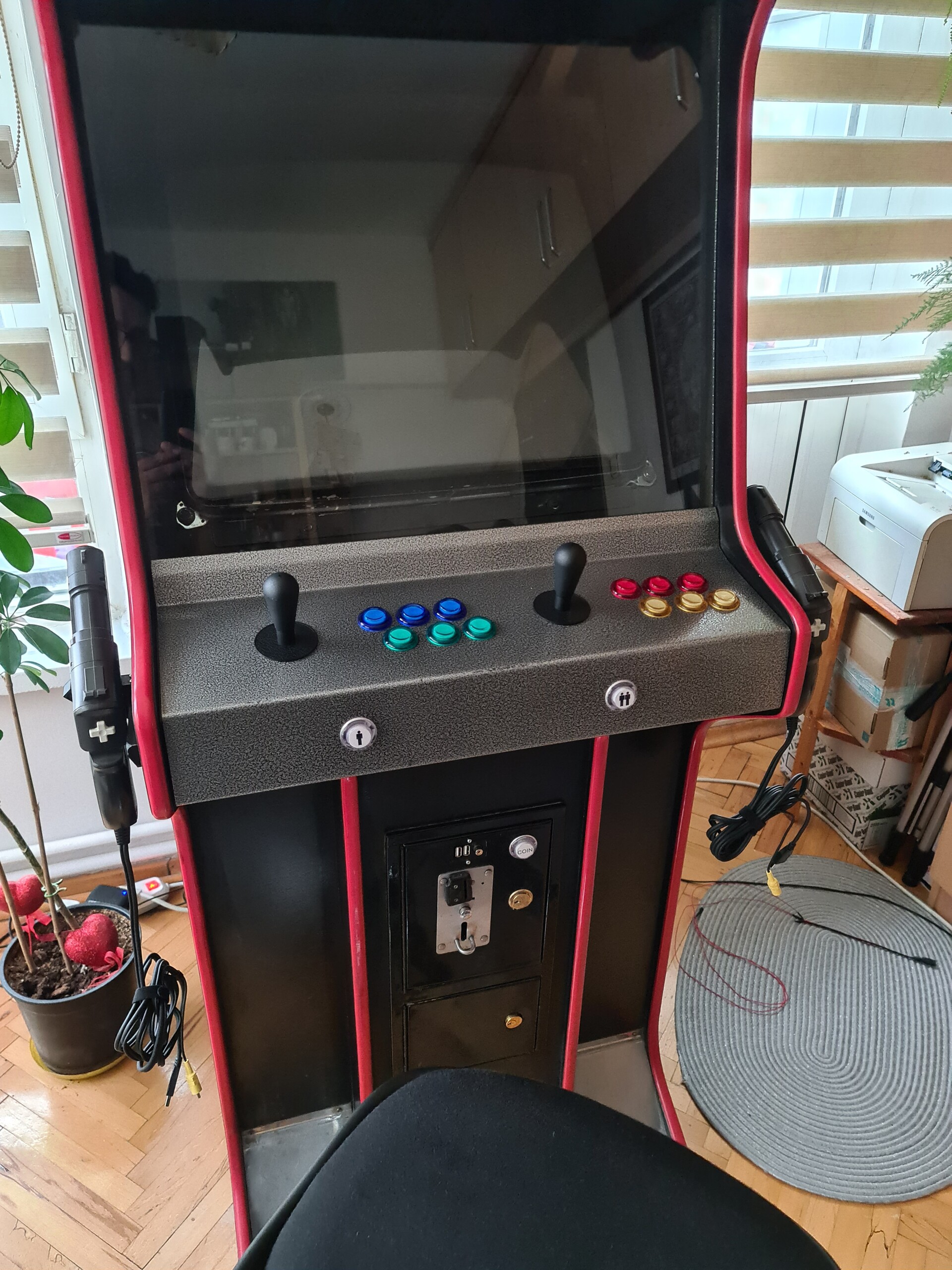
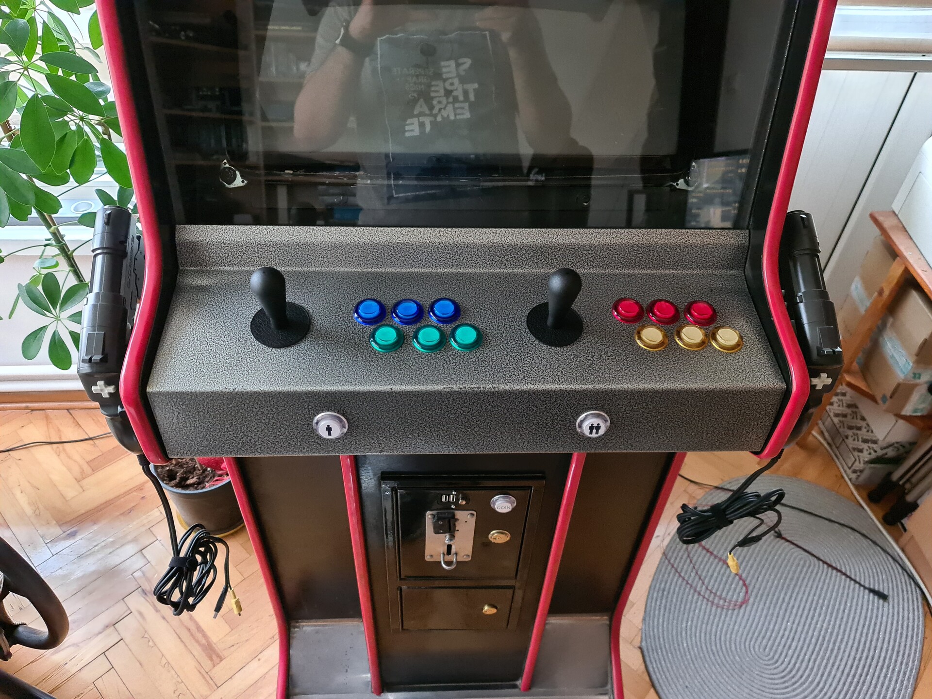
I printed the curve sketch of the holes for the controller board and I drilled the holes through it.

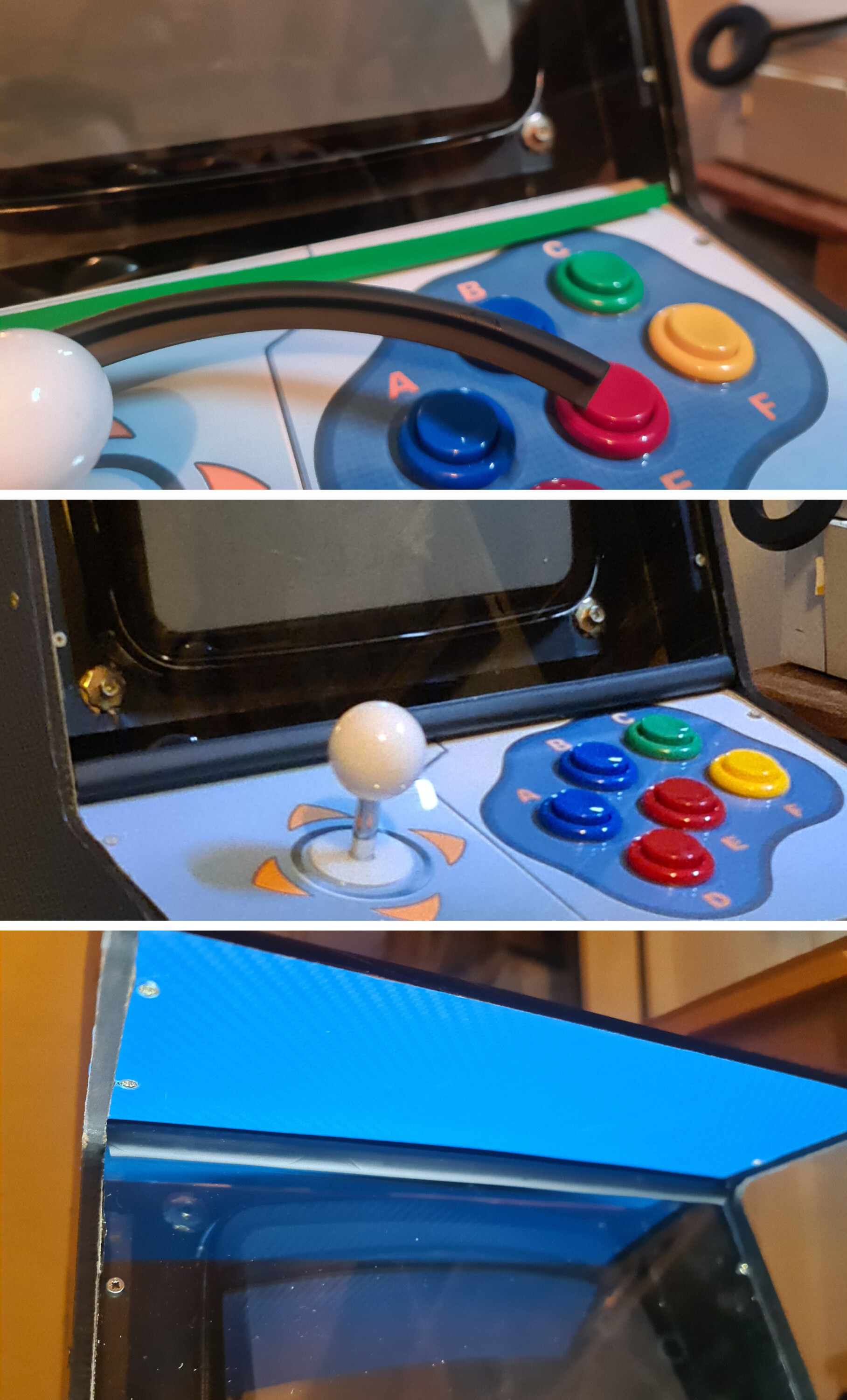
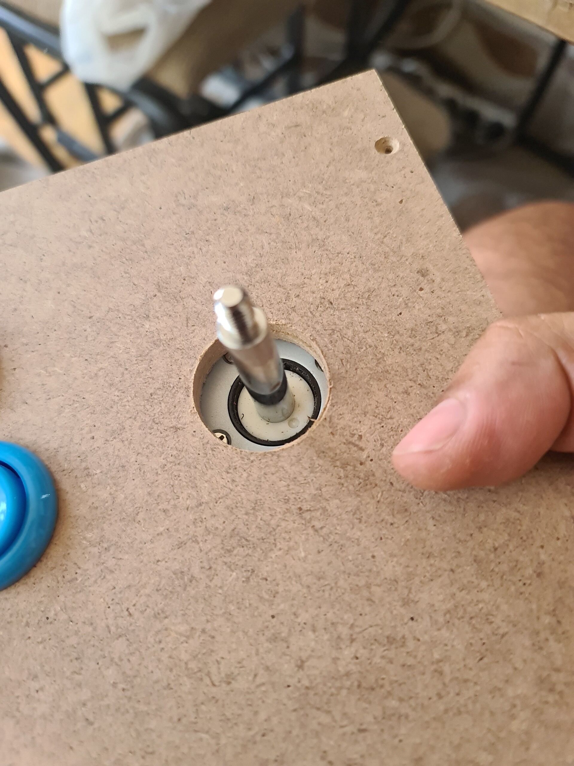
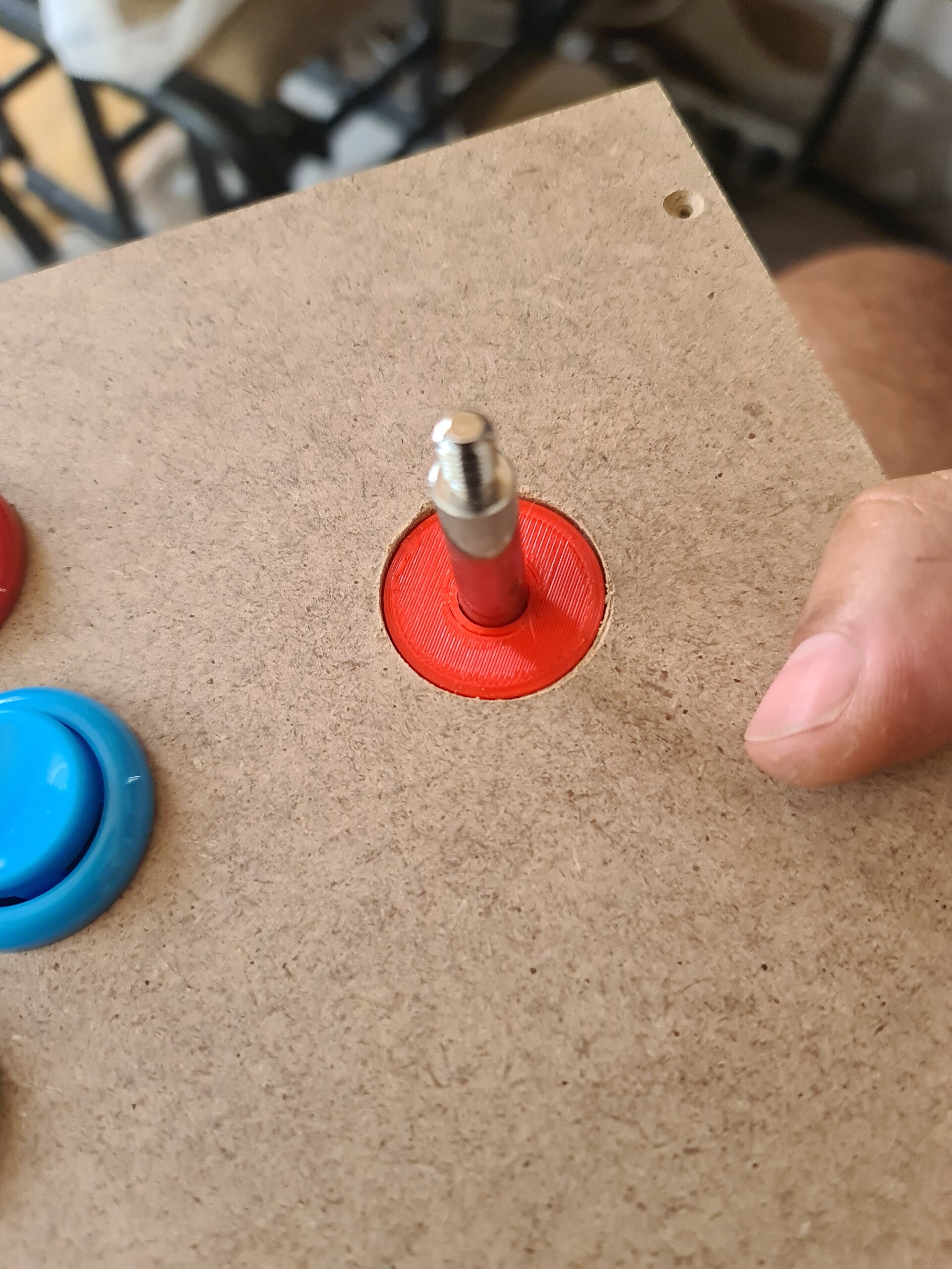
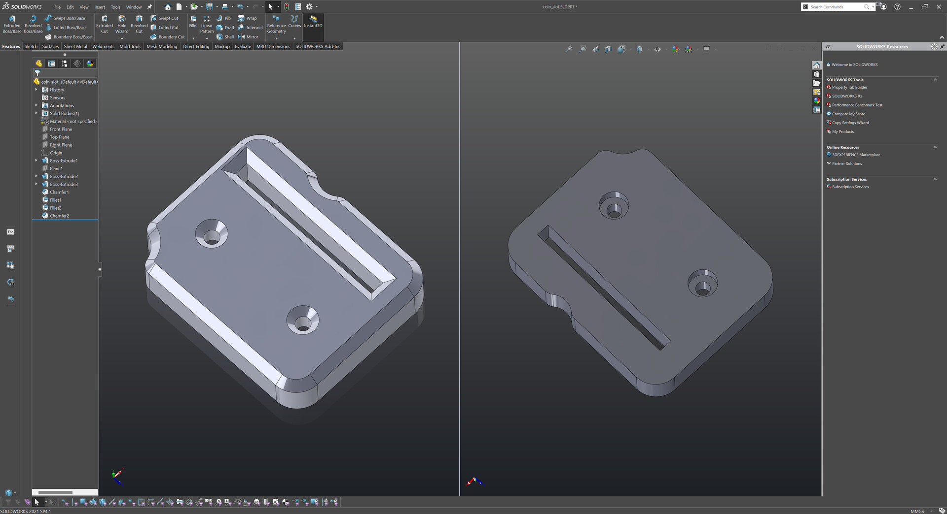
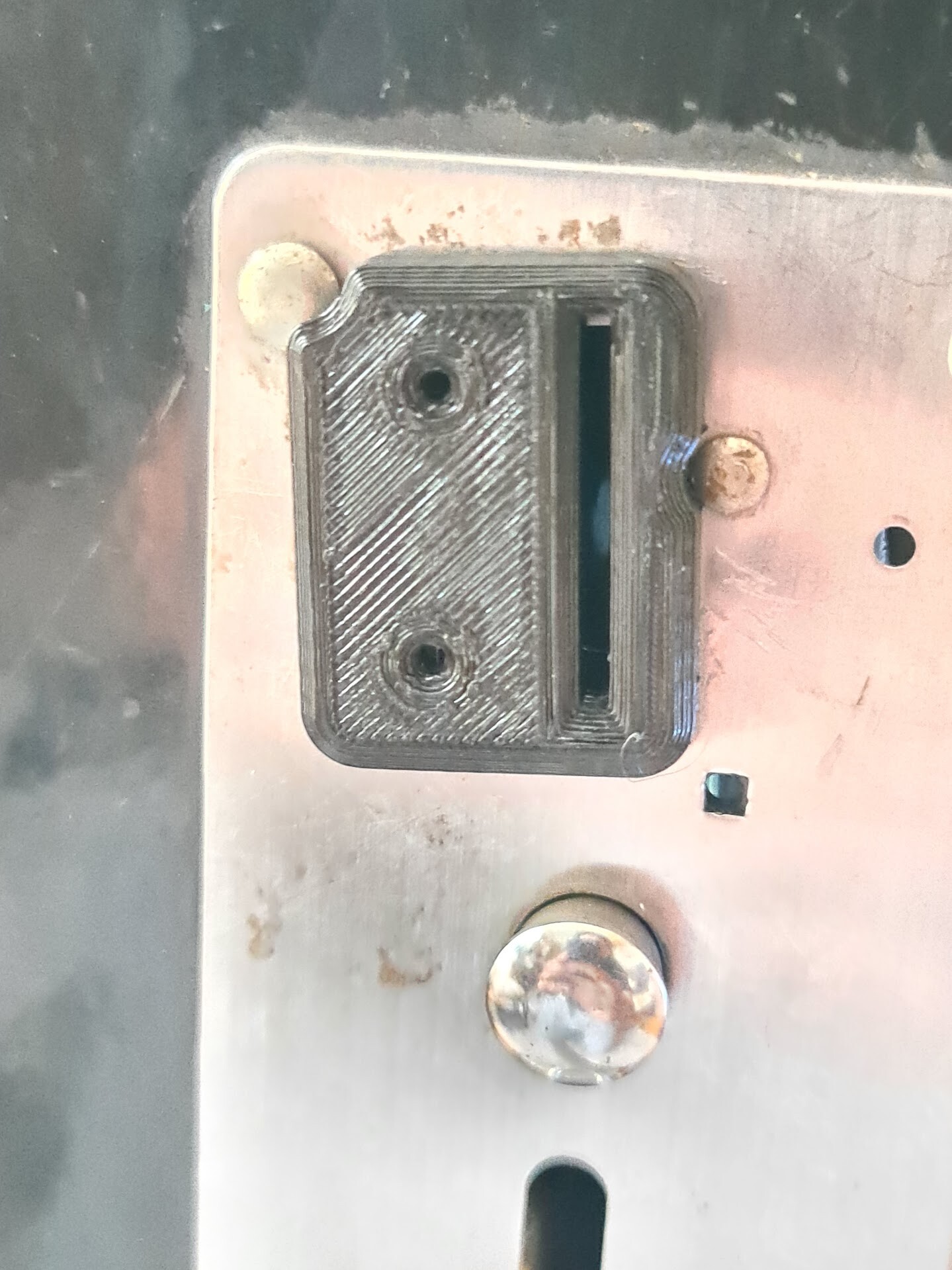
I screwed the controllers from the backside but before doing that, I 3d printed an alignment ring to locate the controller centered with the hole on the controller board.

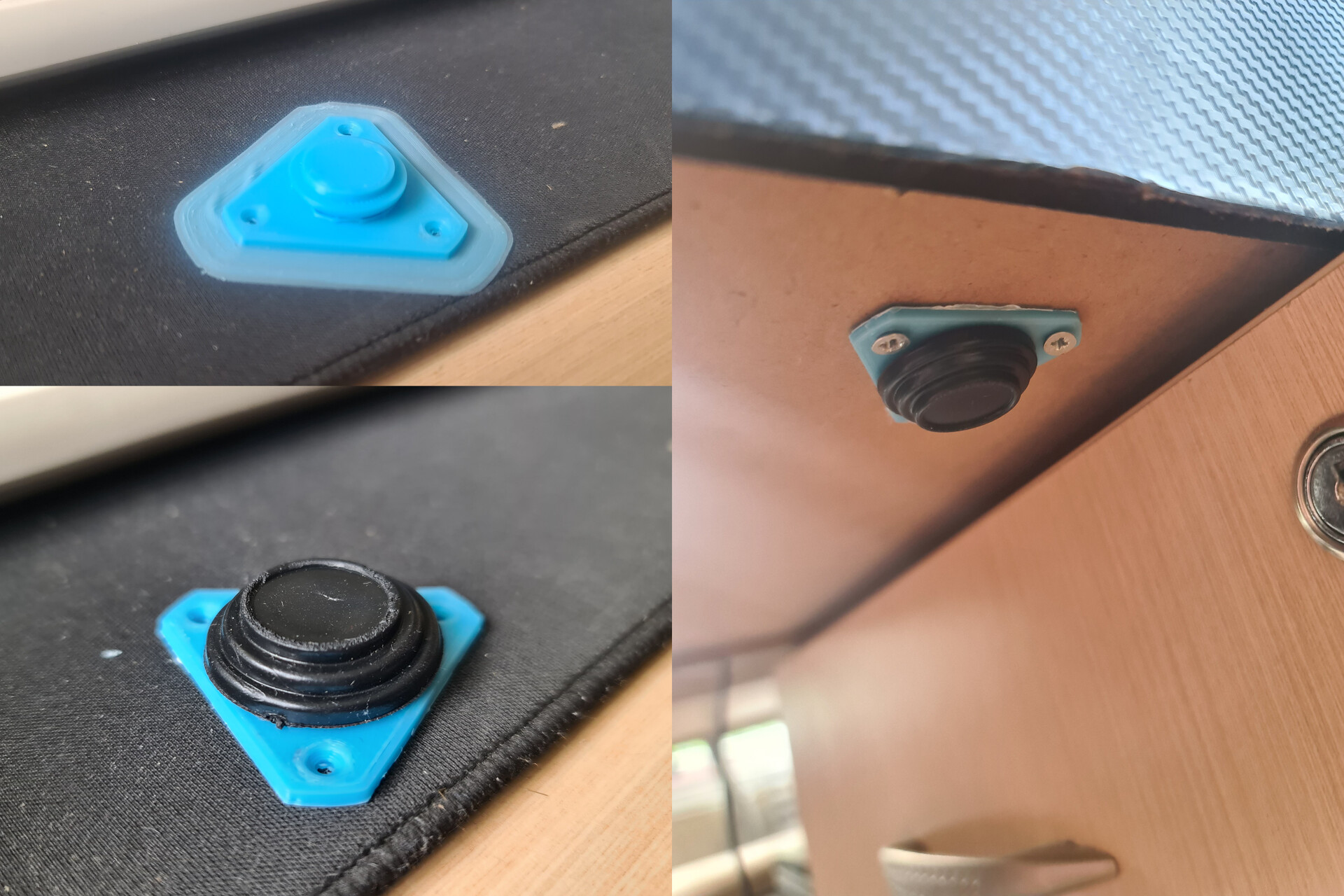
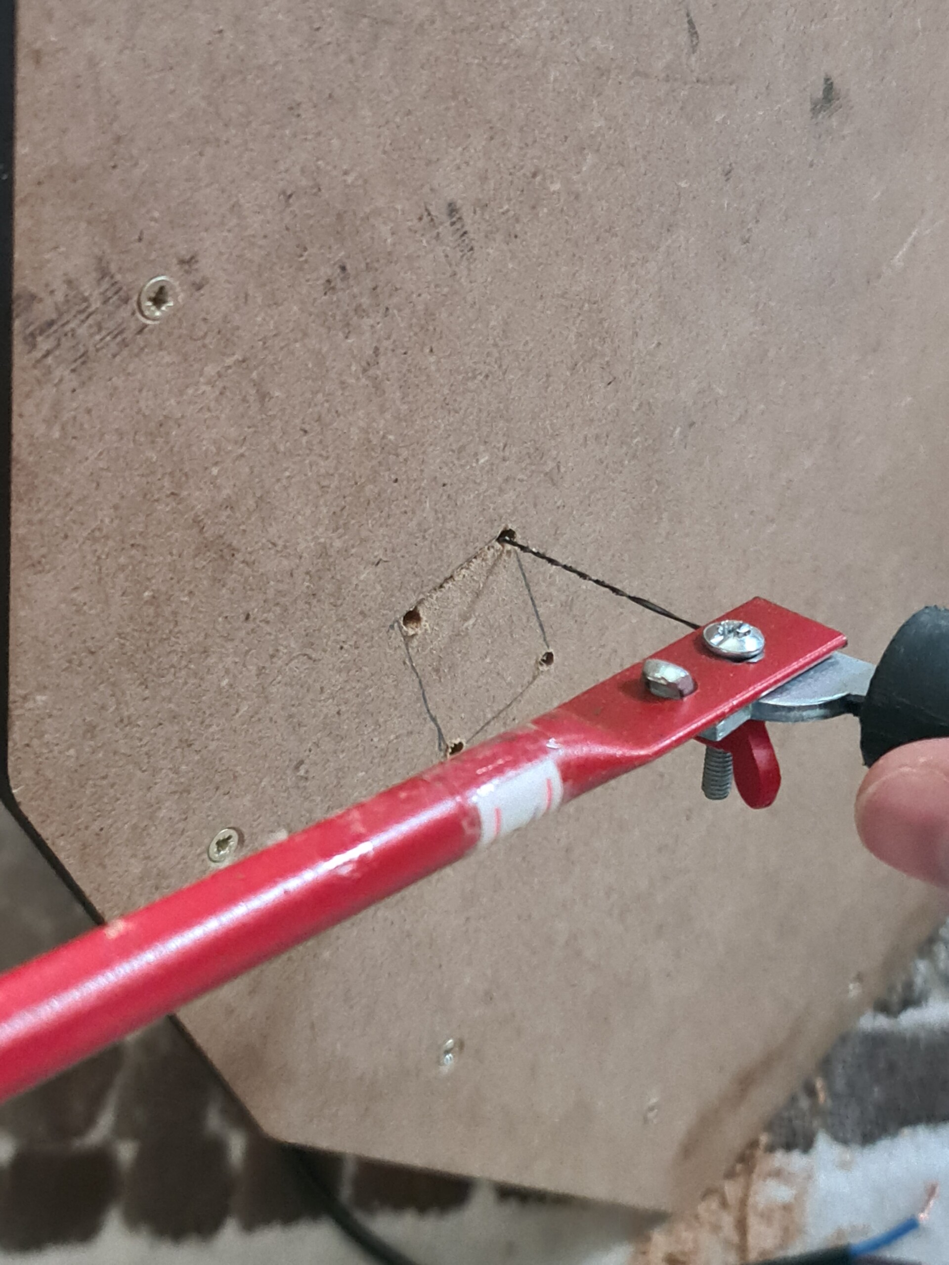
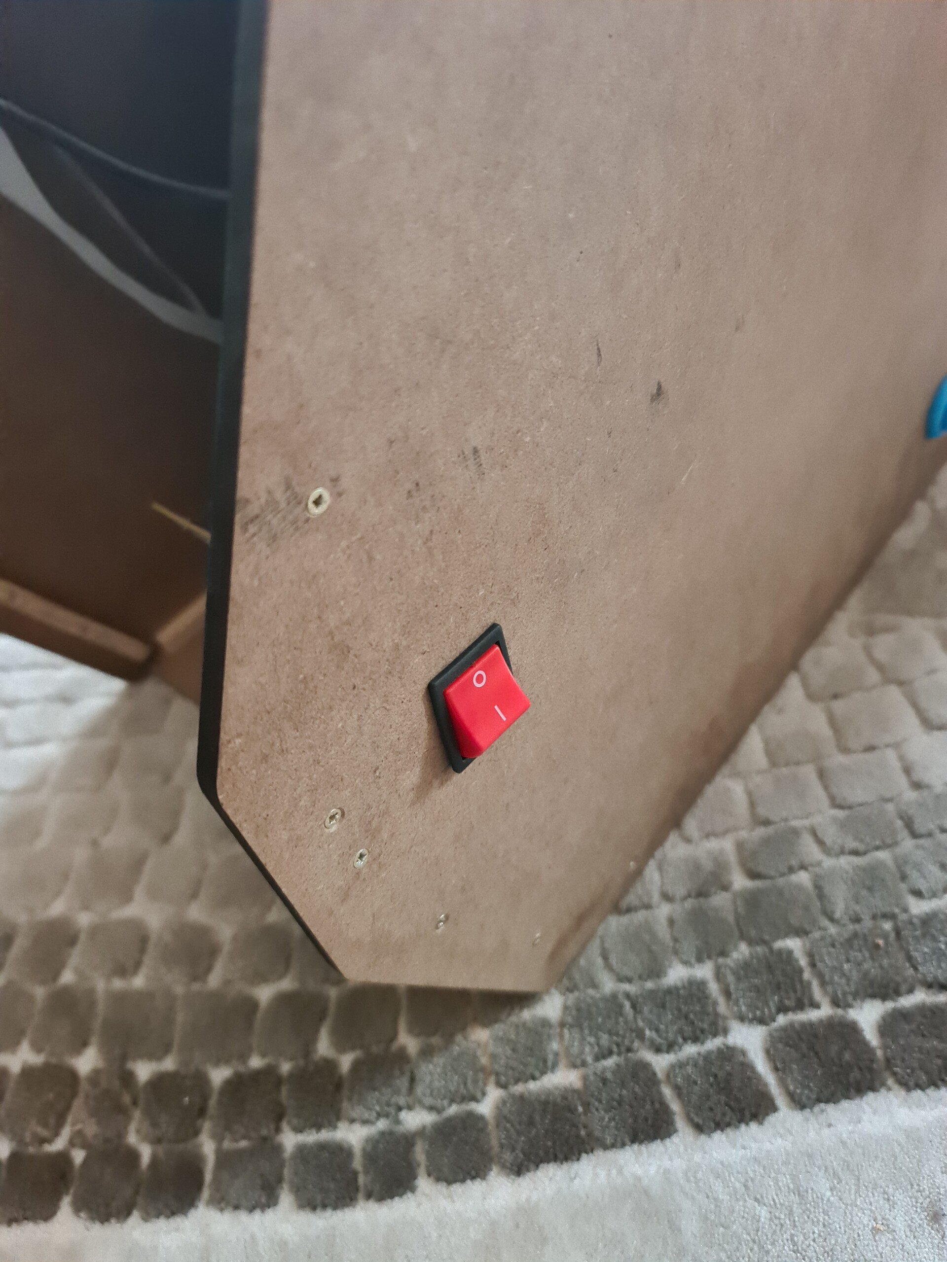
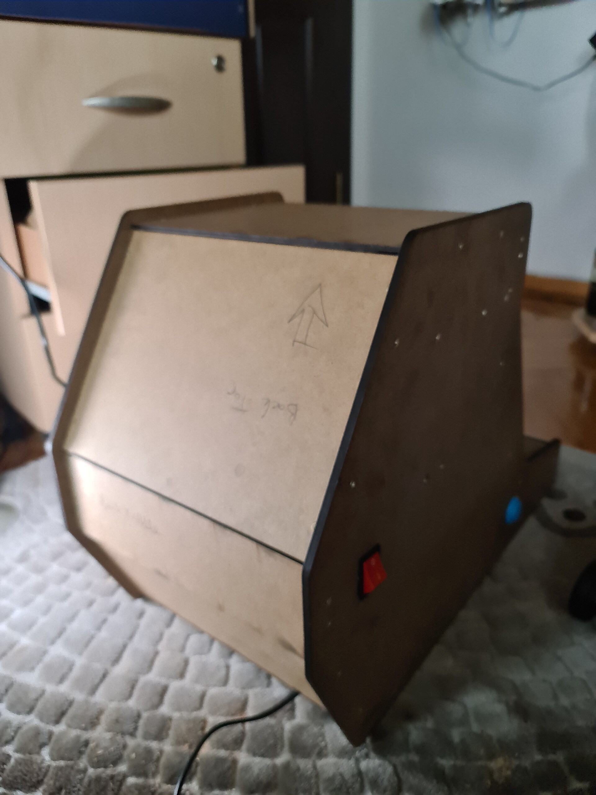
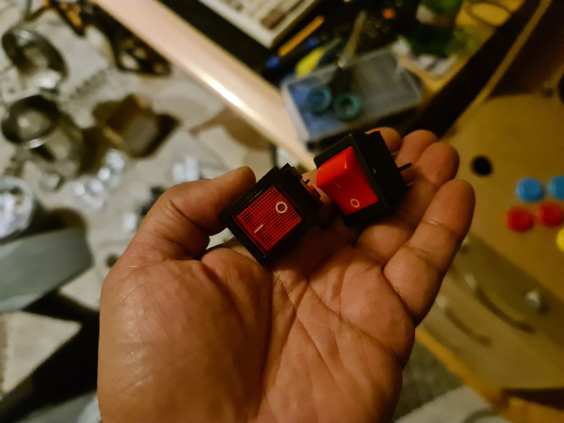
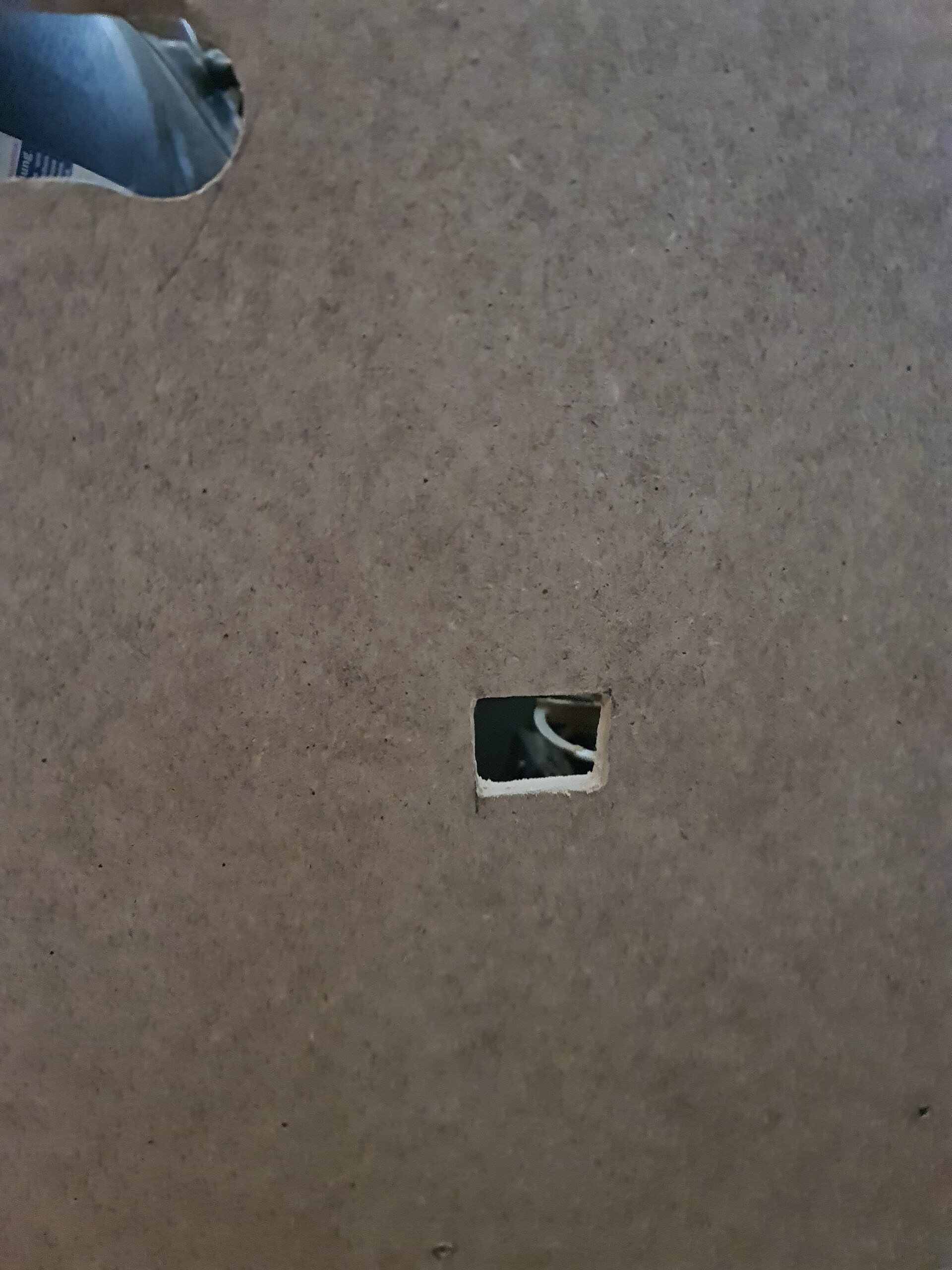
Next I connected and soldered a 220V on/off switch to the right side. 

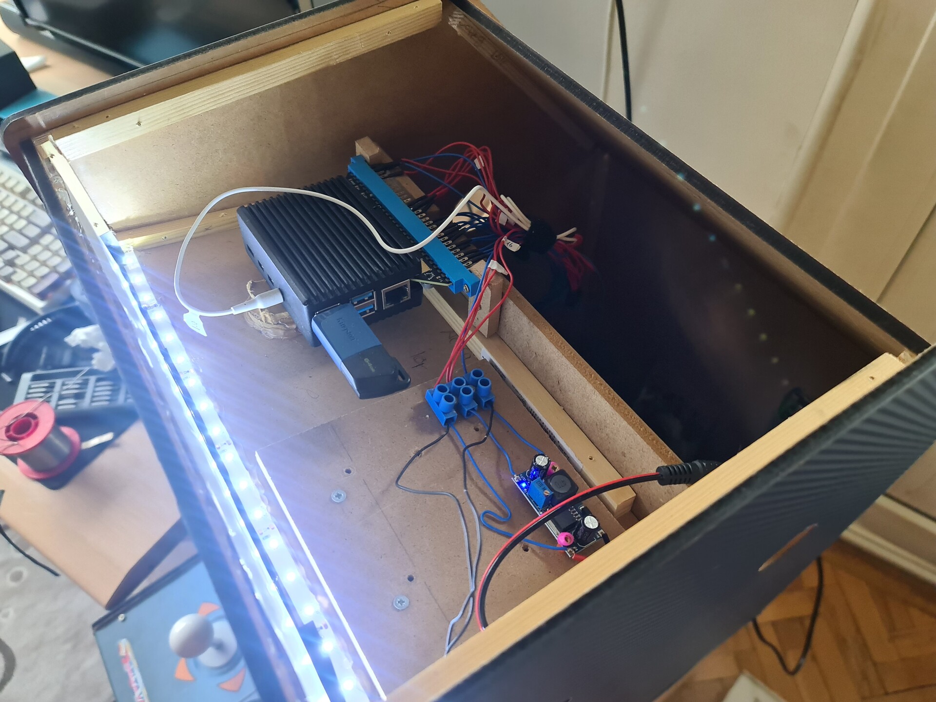
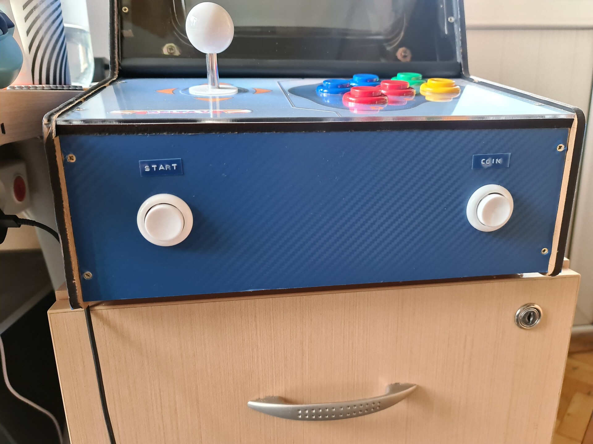
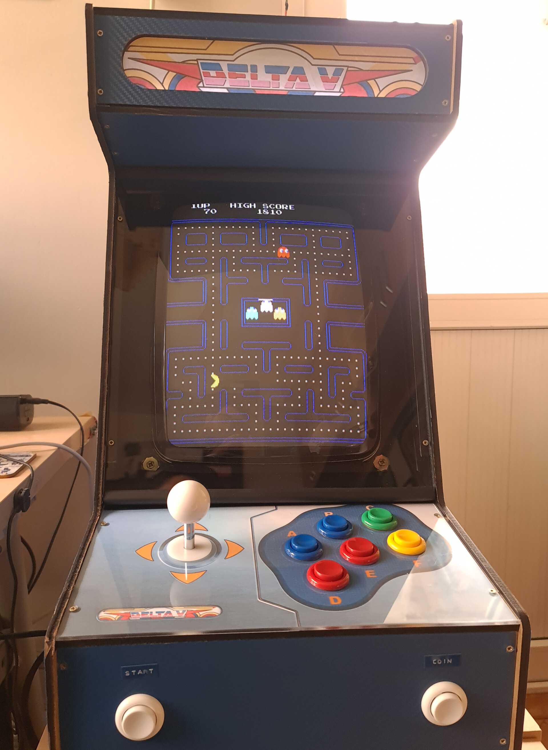
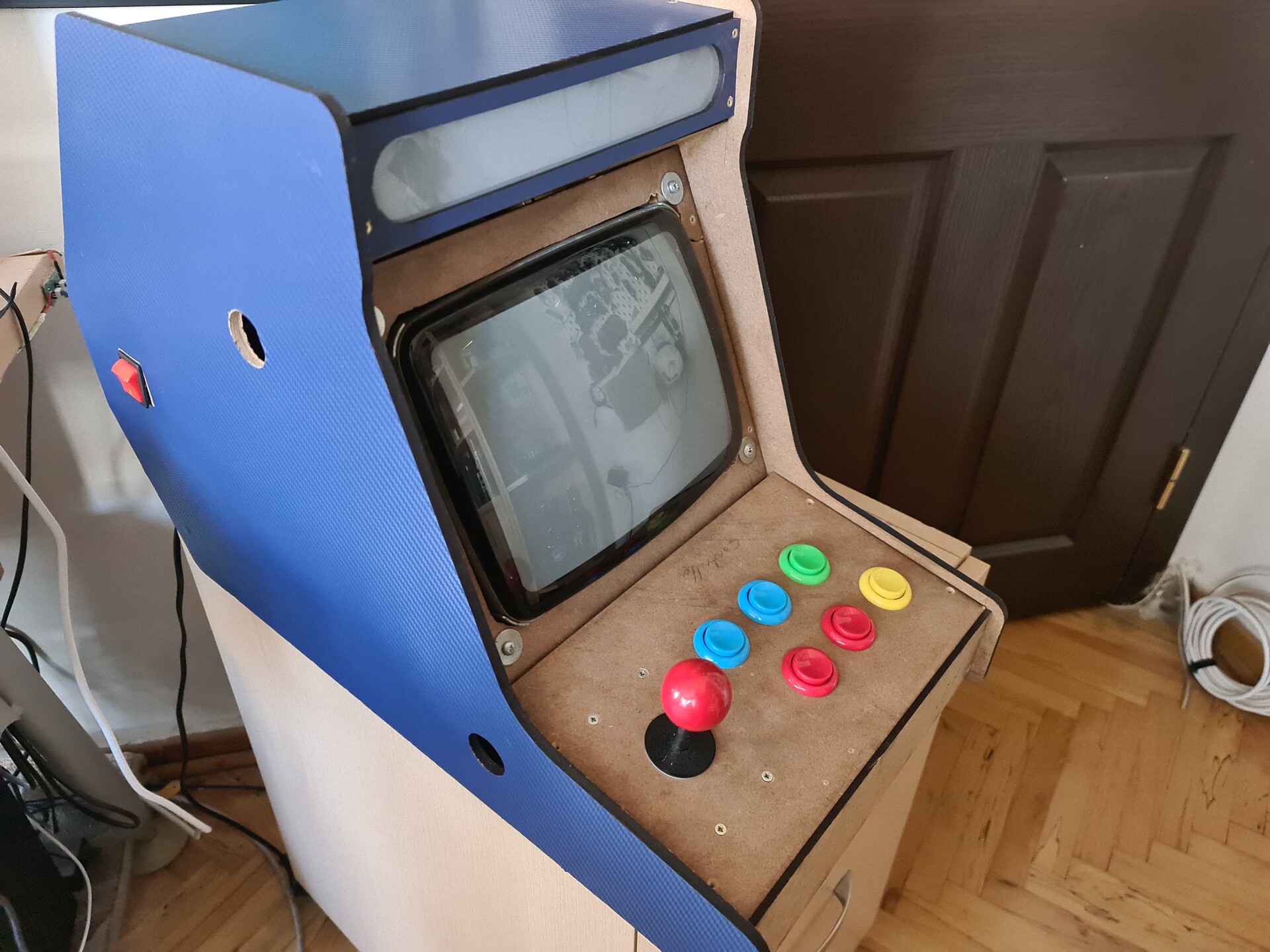
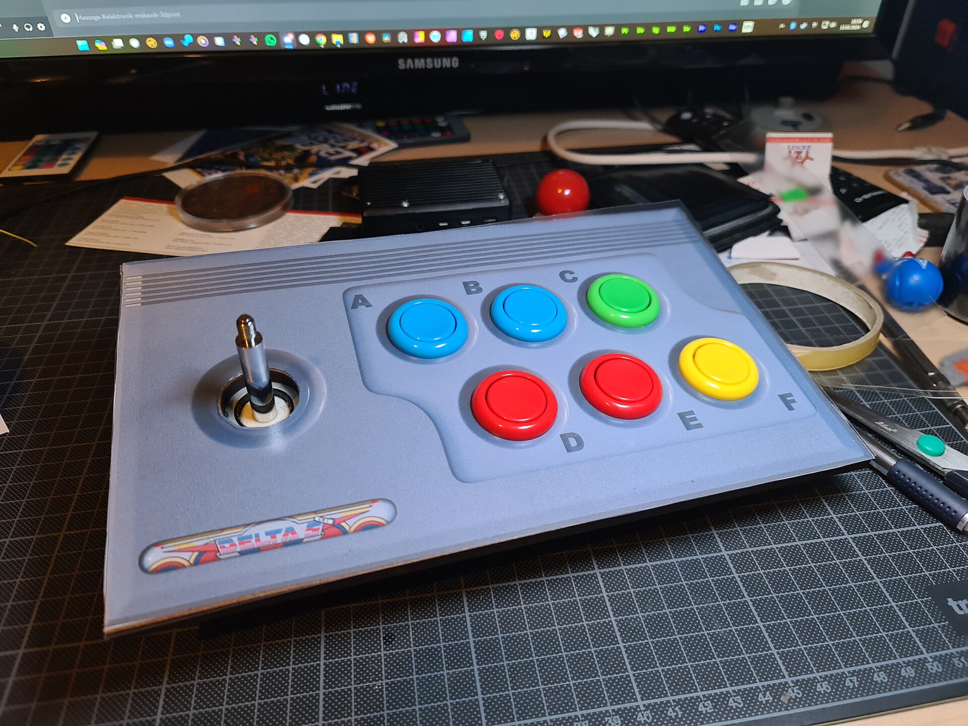
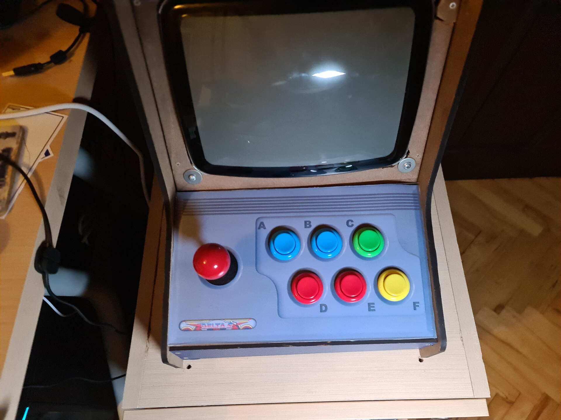
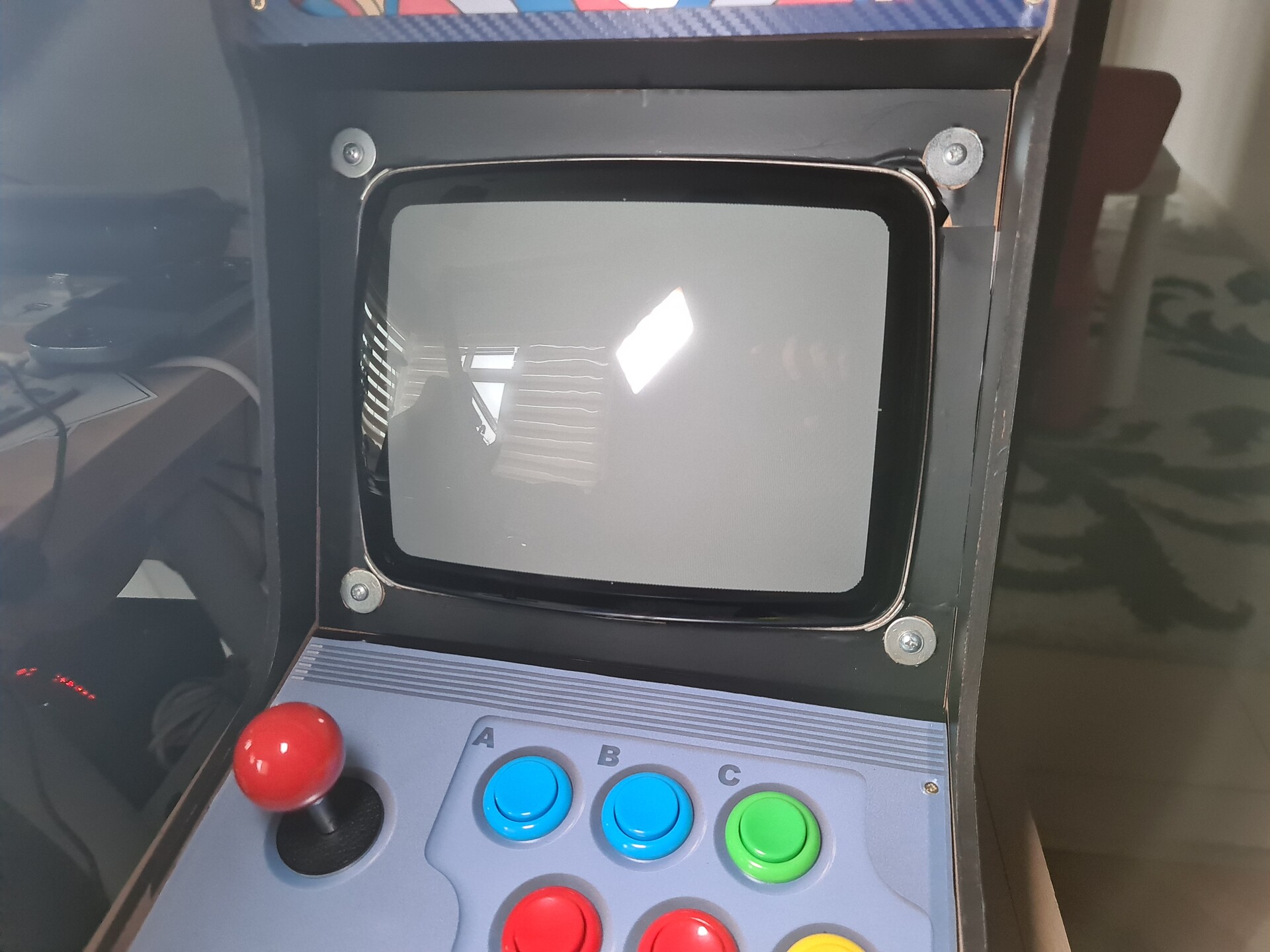
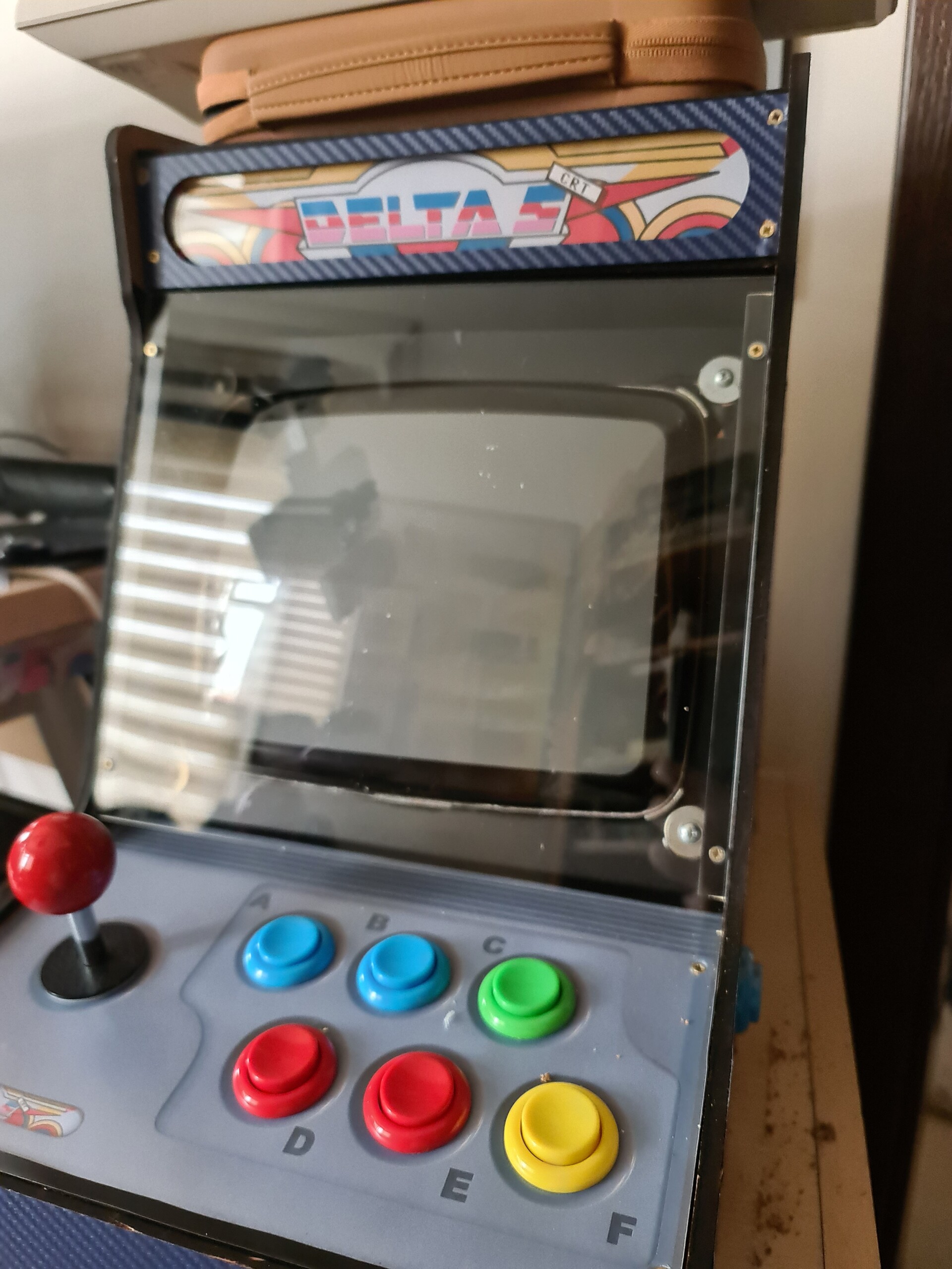
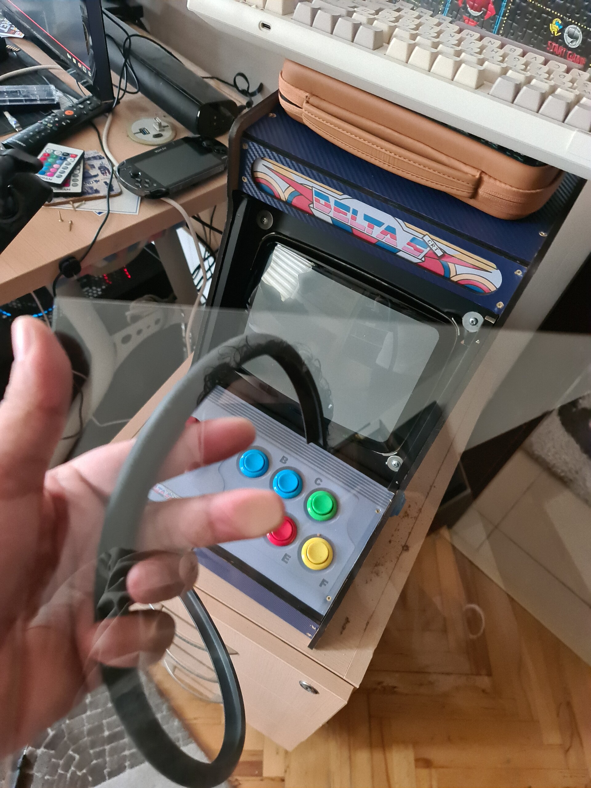
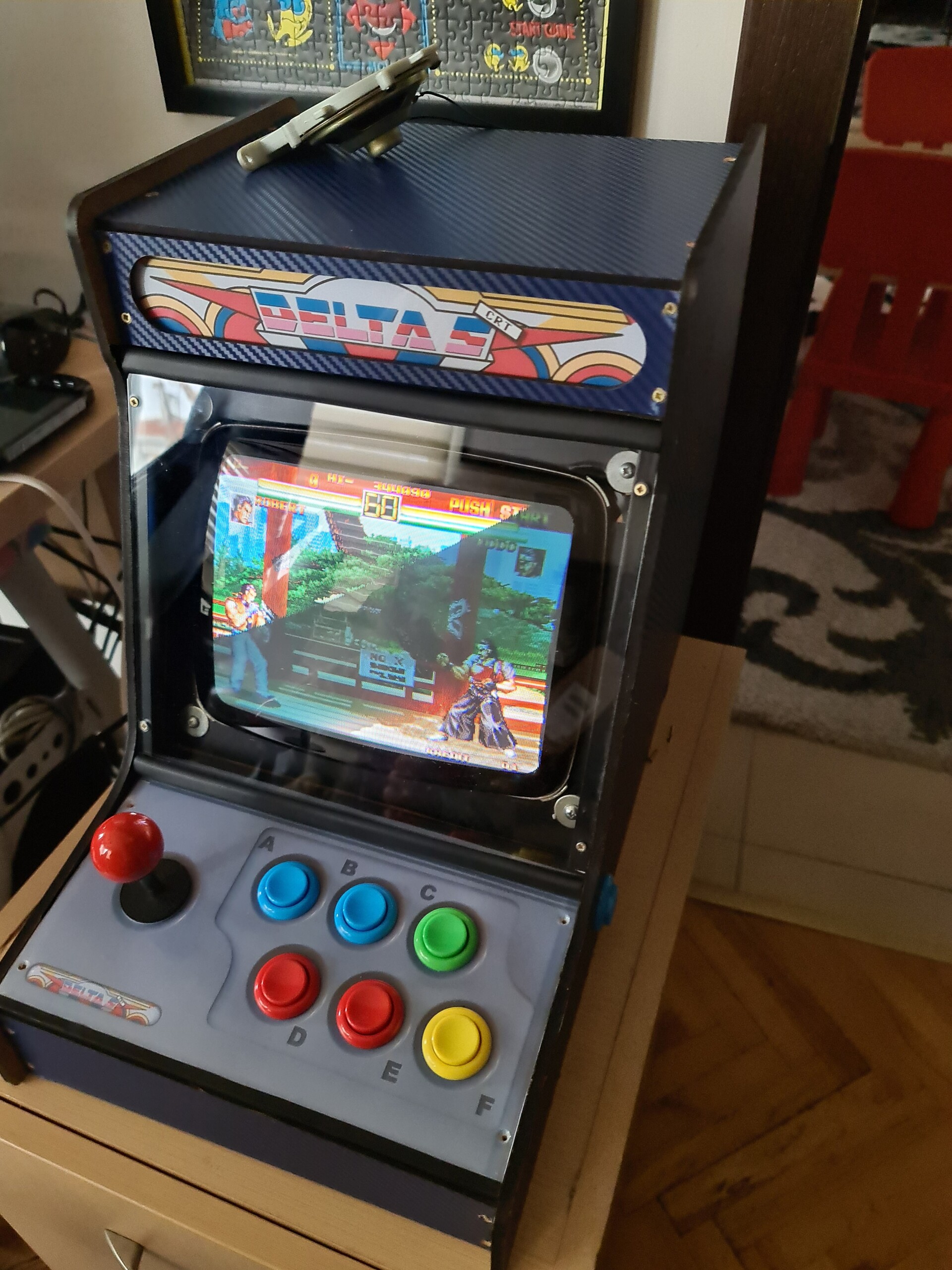
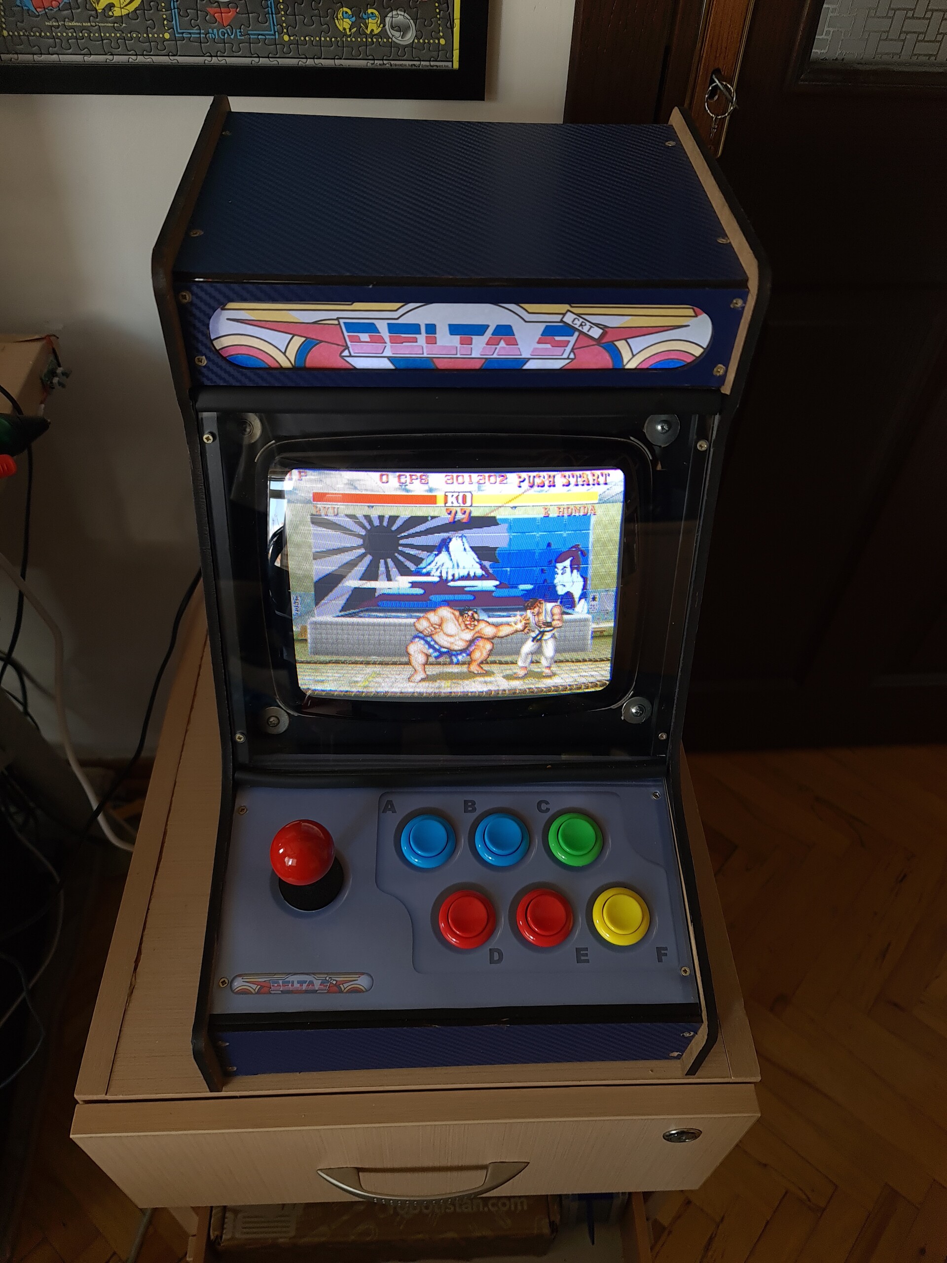
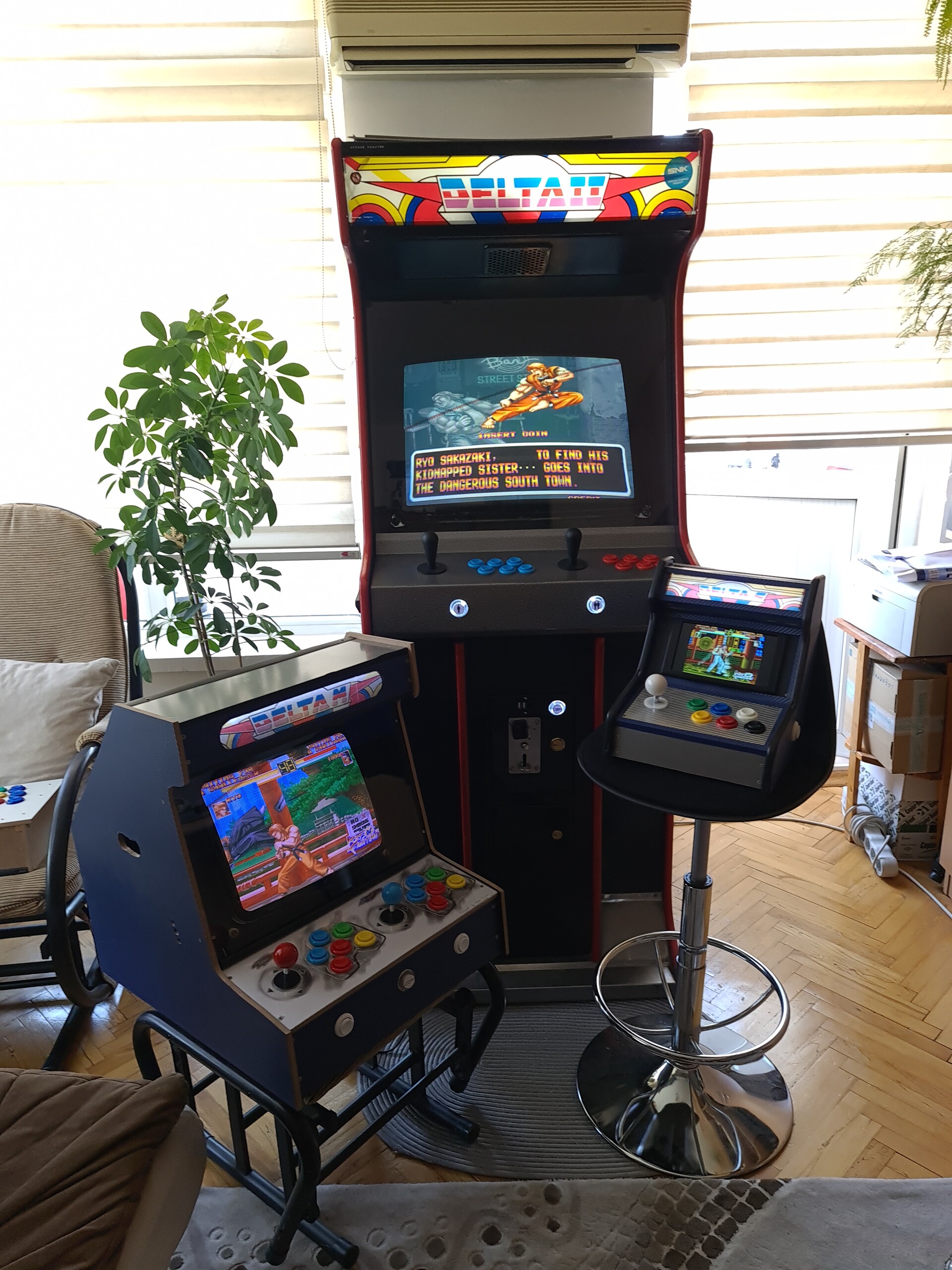
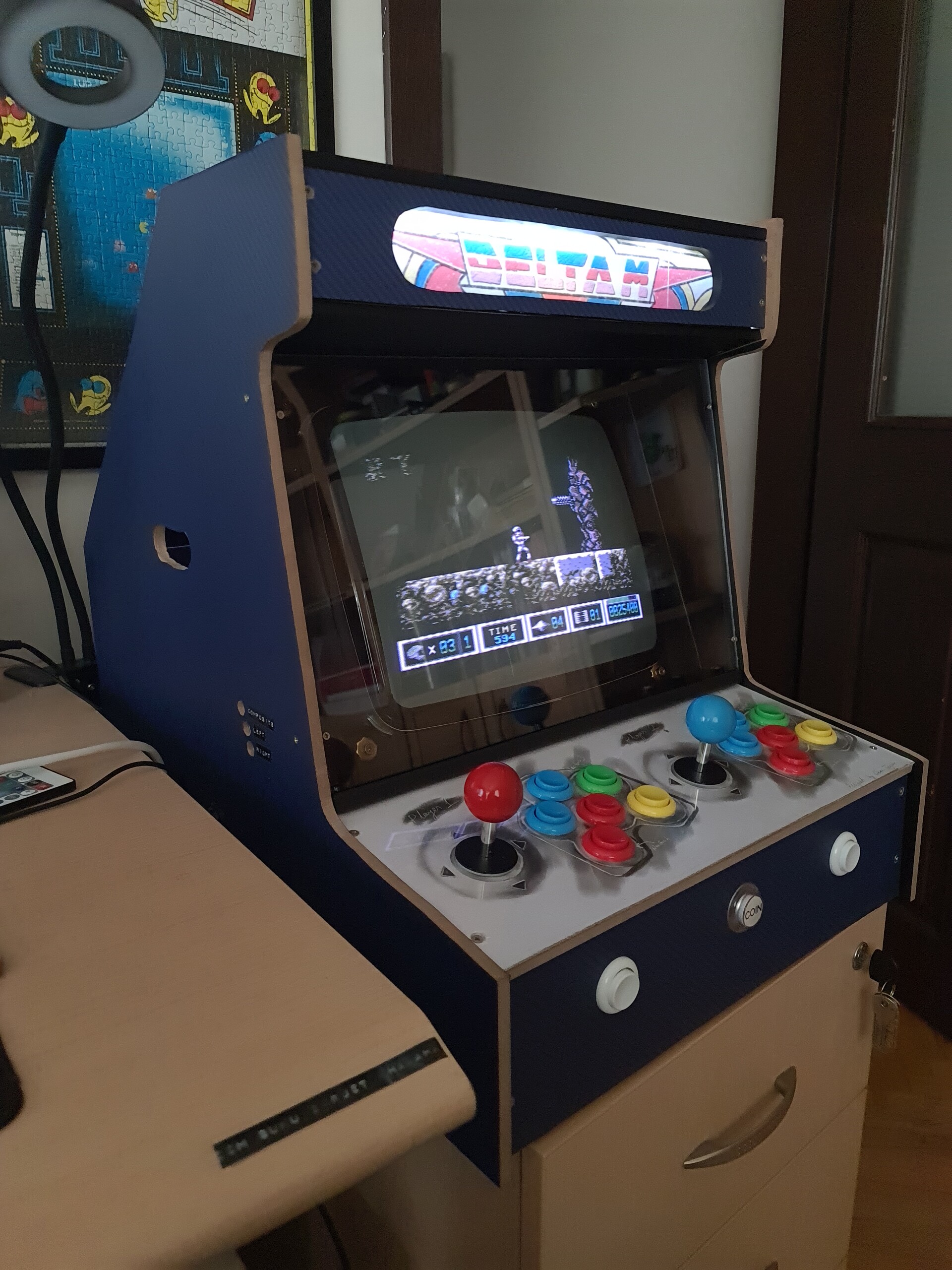
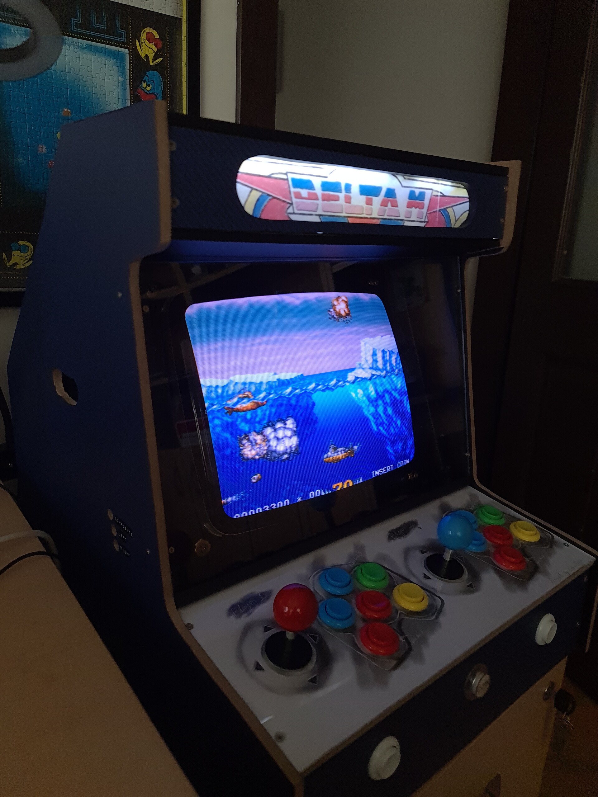
This is how the cabinet looks so far.

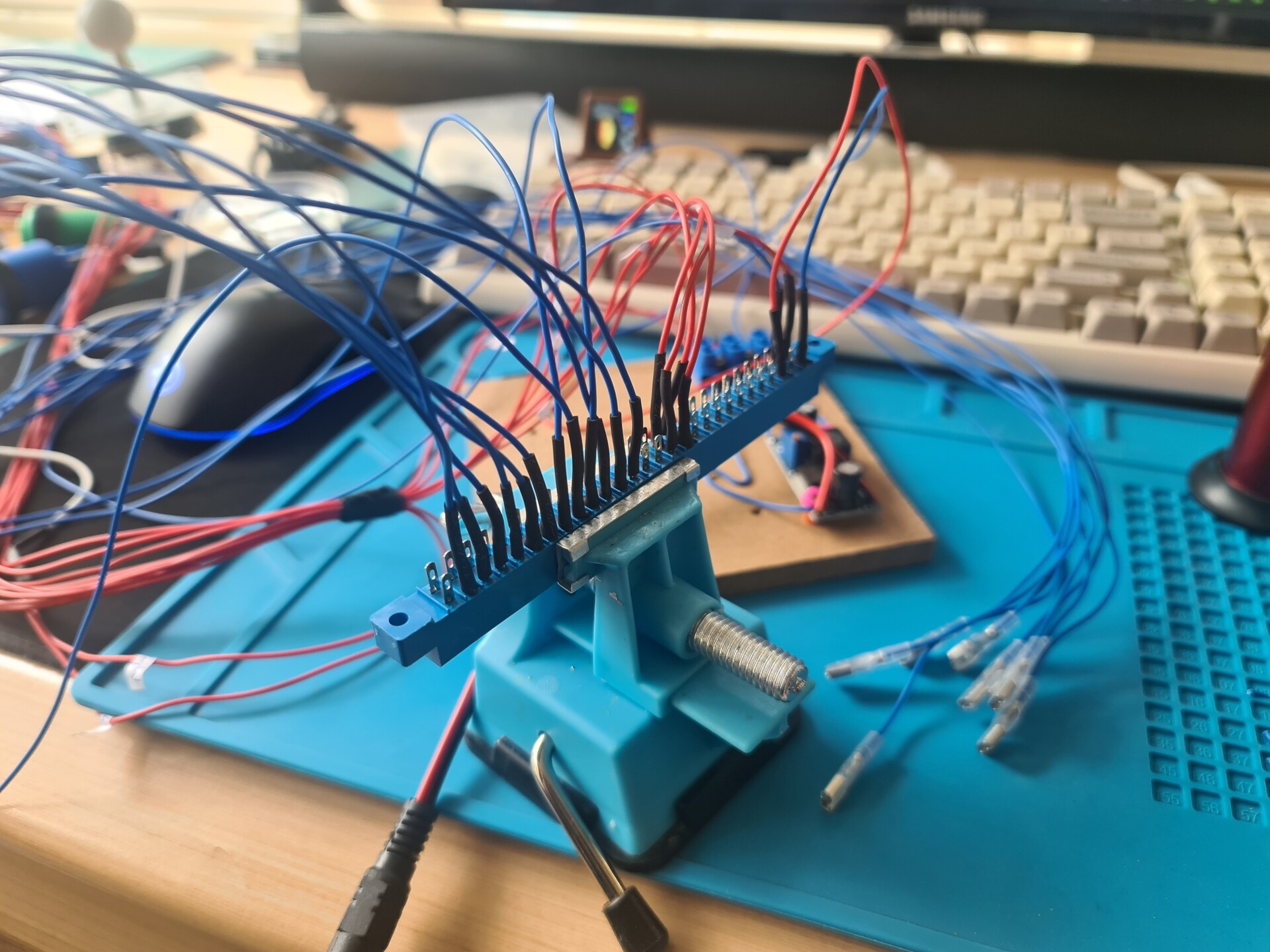
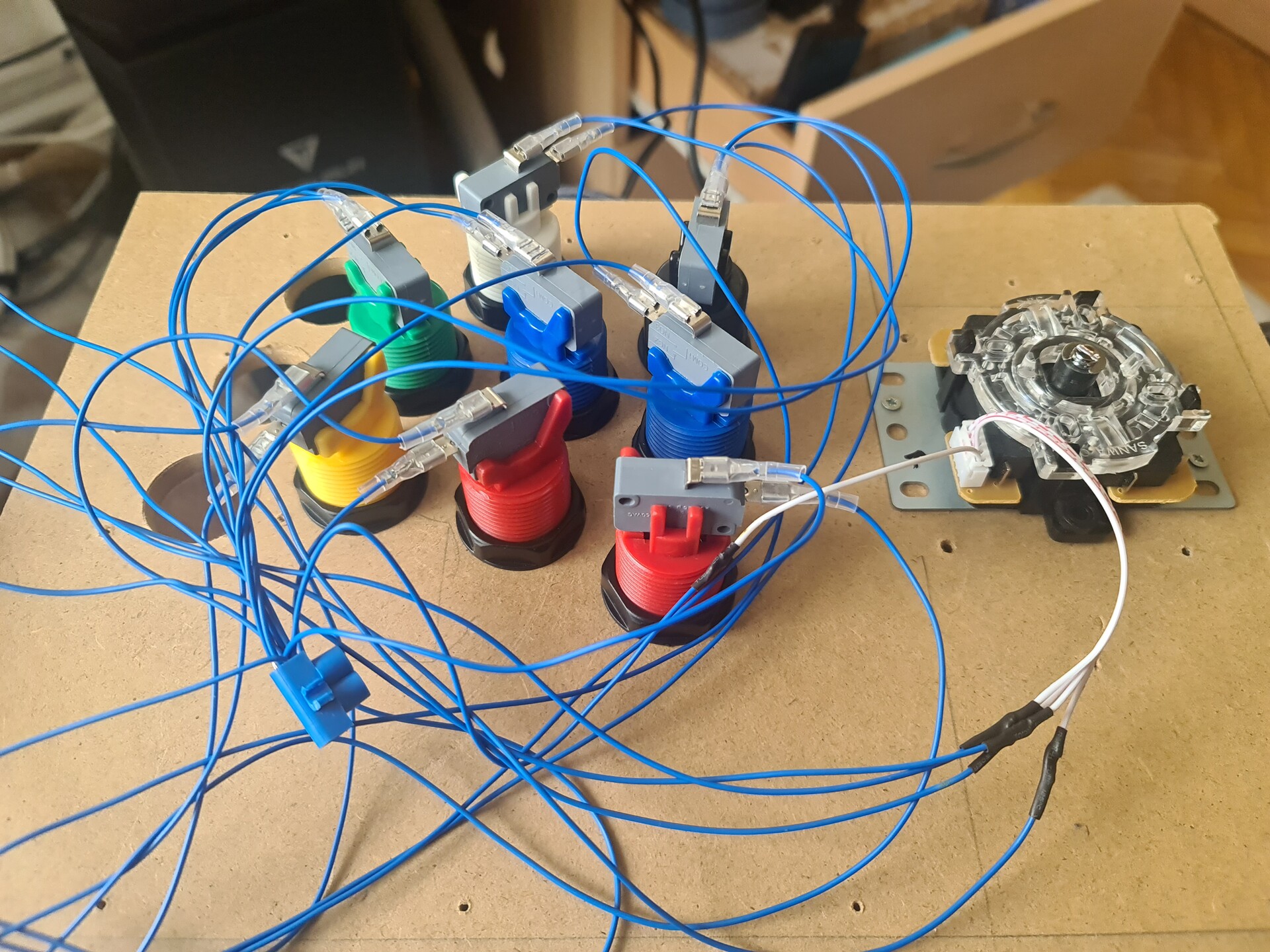
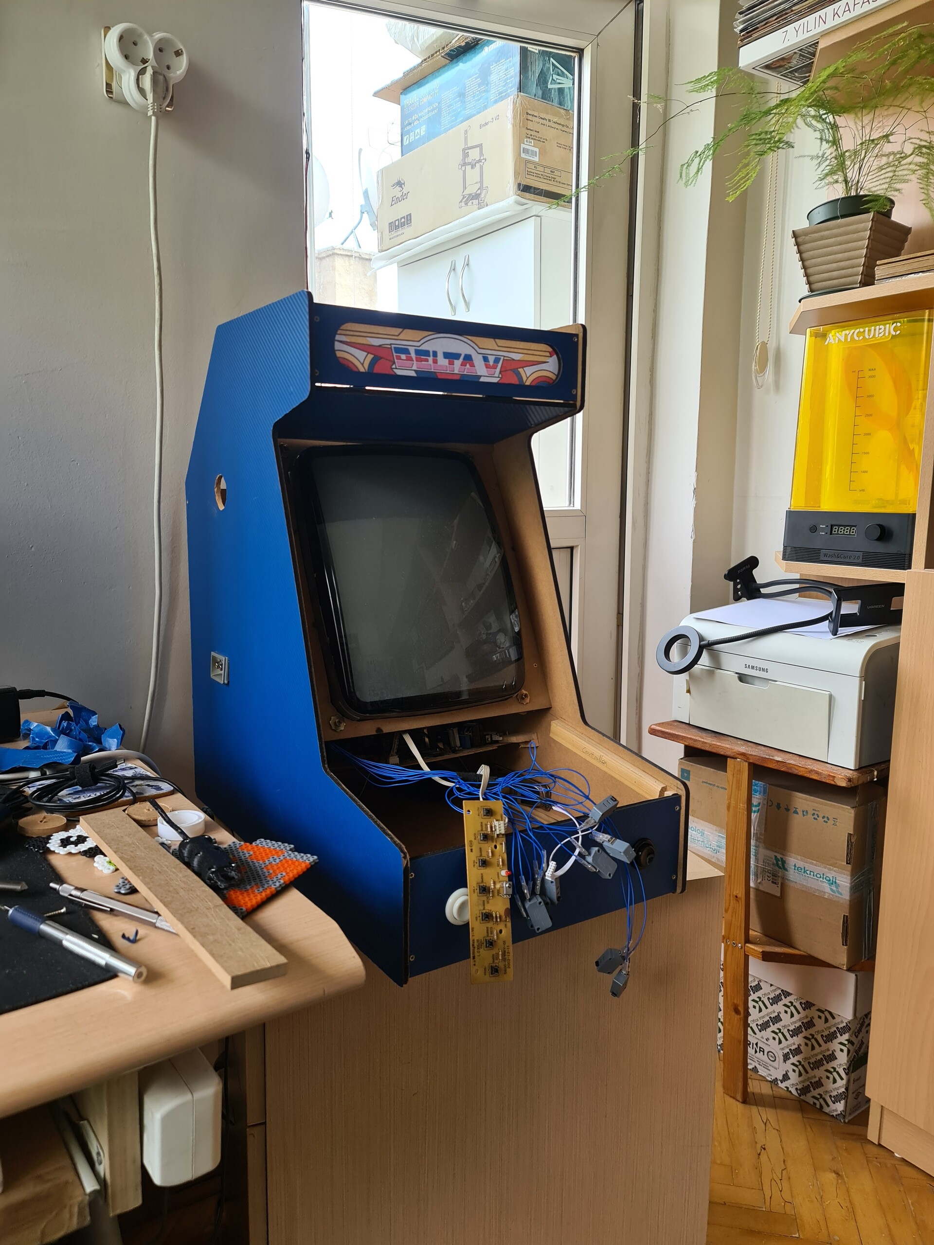
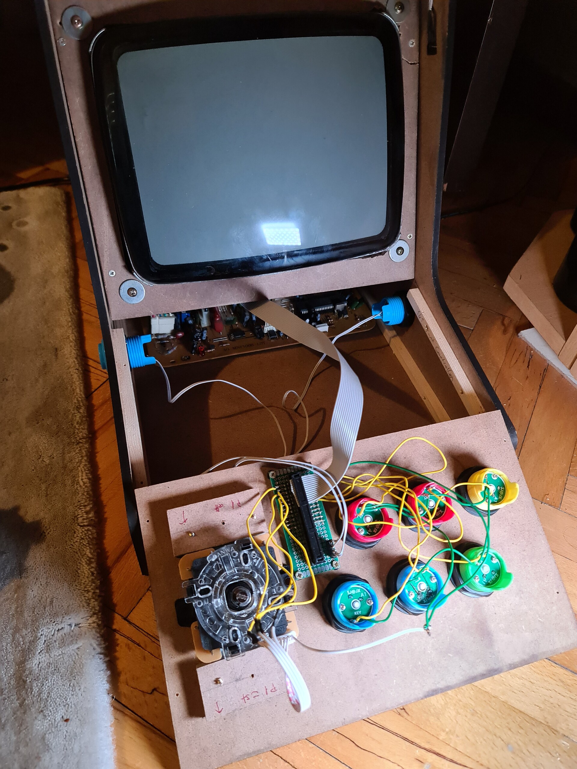
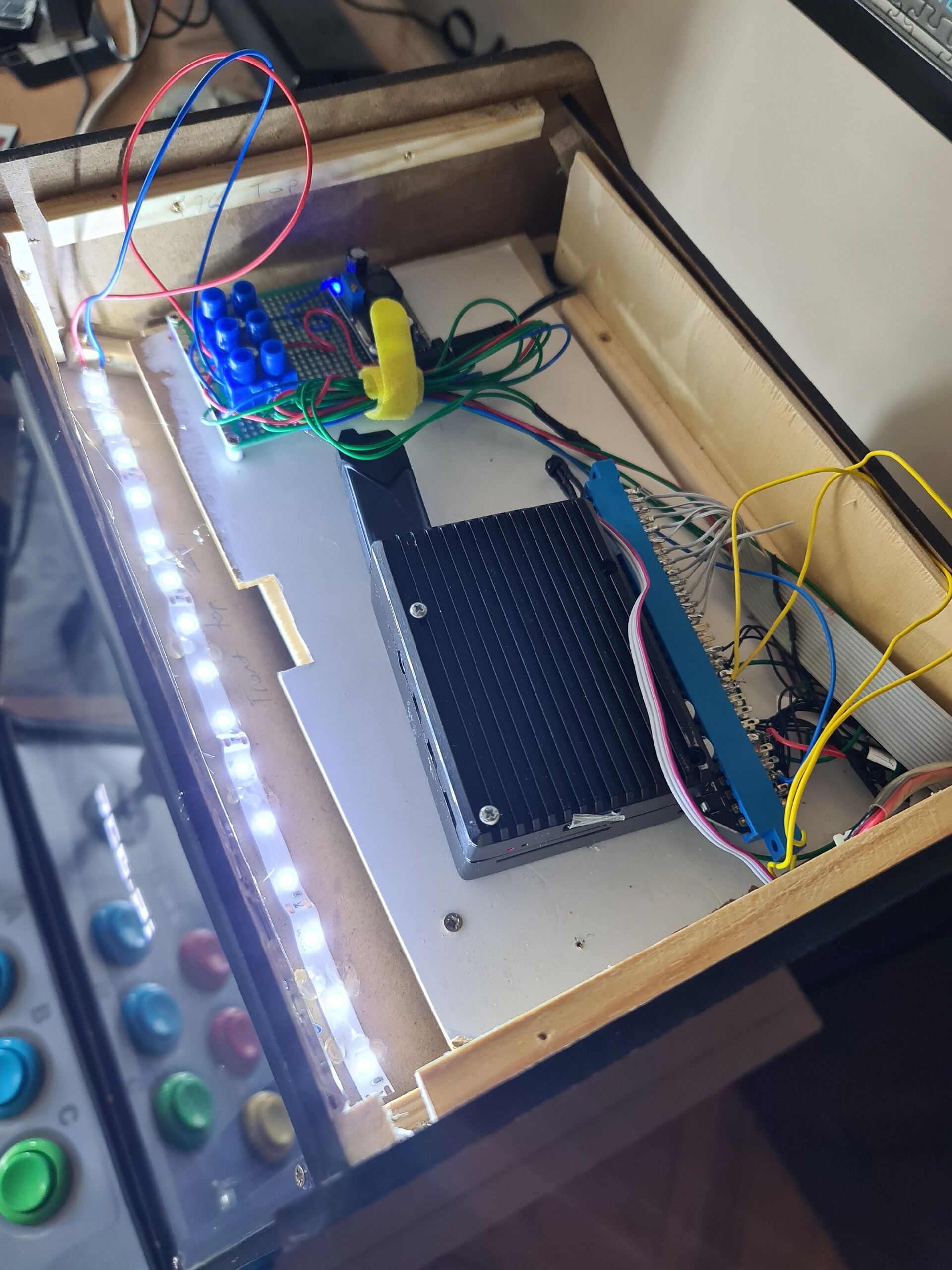
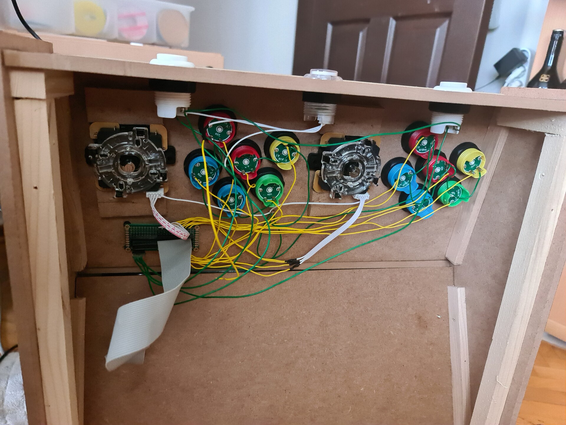
Since I mounted all the buttons and the joysticks, now it's time for cabling. I made the cabling by having the ability demount the control panel entirely. So I added connectors to the both cabinet side cables and control panel cables. I soldered a 40 pin connector to the controller board so I can connect the pins by a flex cable from controller panel to Raspberry Pi.

This is how it's mounted to the cabinet. I will connect the 40-pin flex cable to the jamma part.

Next I soldered cables to jamma for Player 1 and Player 2 controls, and I terminated these cables with another 40-pin connector.

I followed this diagram and applied it to jamma connector for the controller pinouts. Source: https://www.mortaca.com/rgb-pi/wiki/index.php?title=RGB-Pi_JAMMA_Installation/en


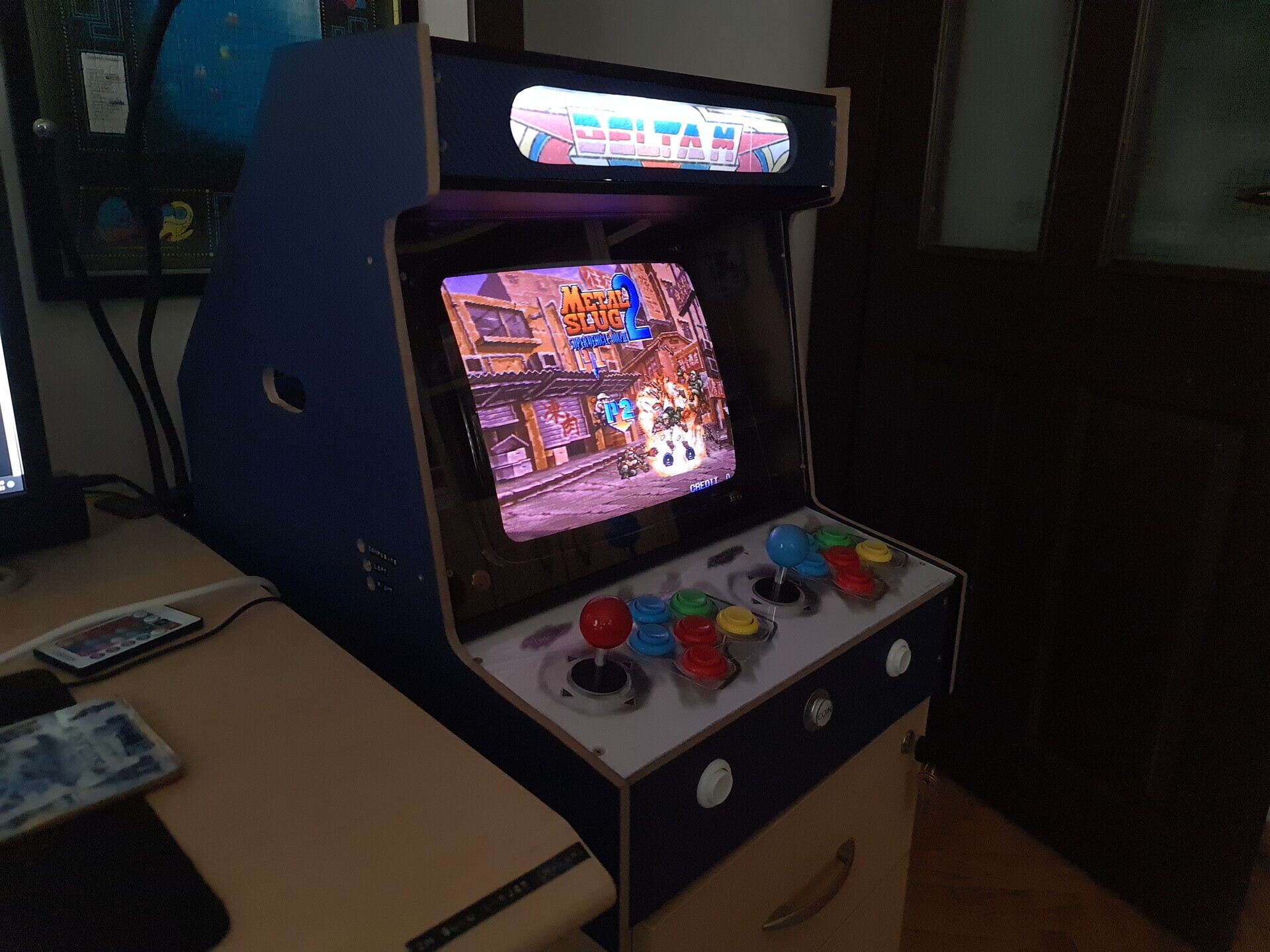
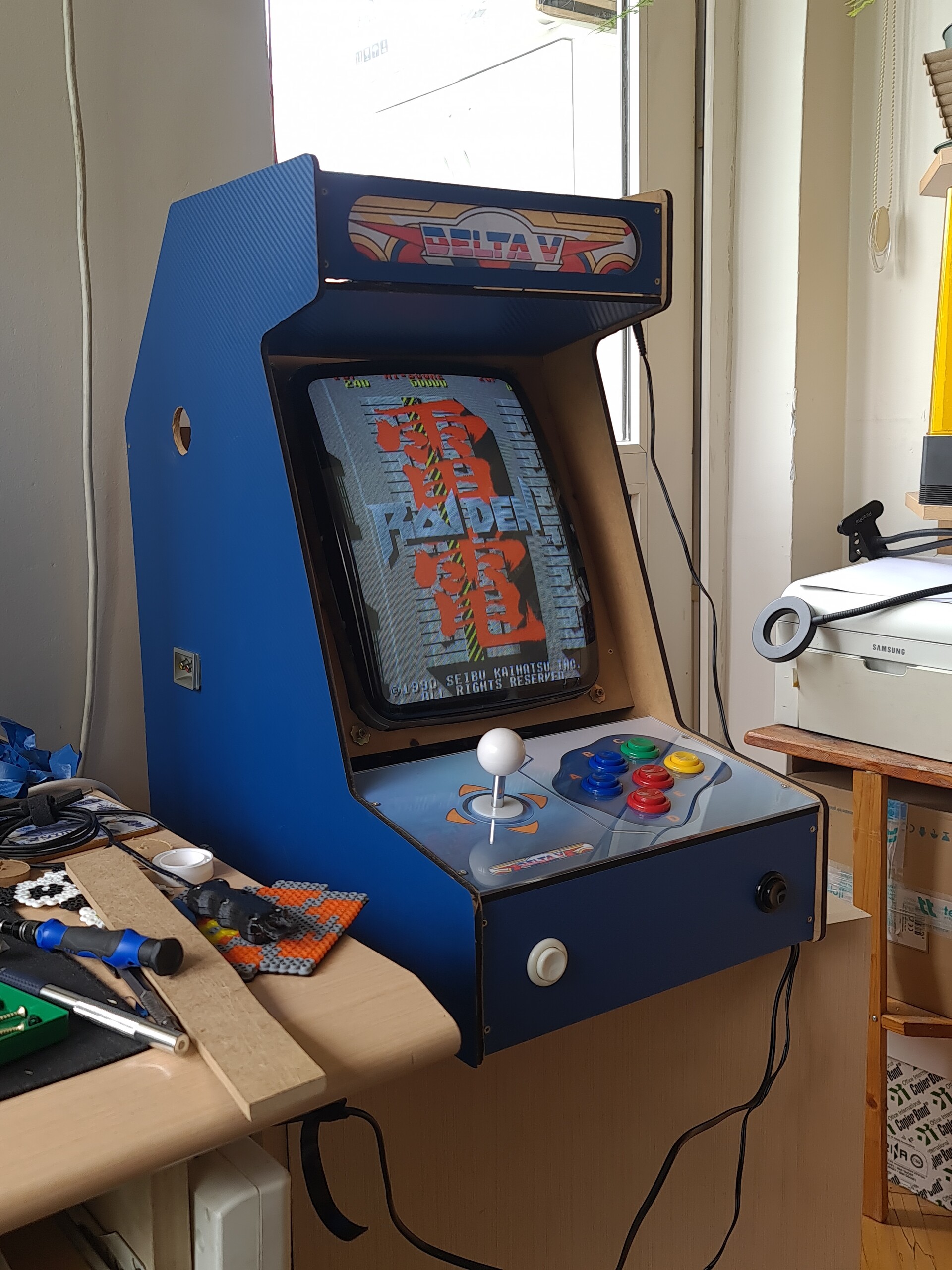
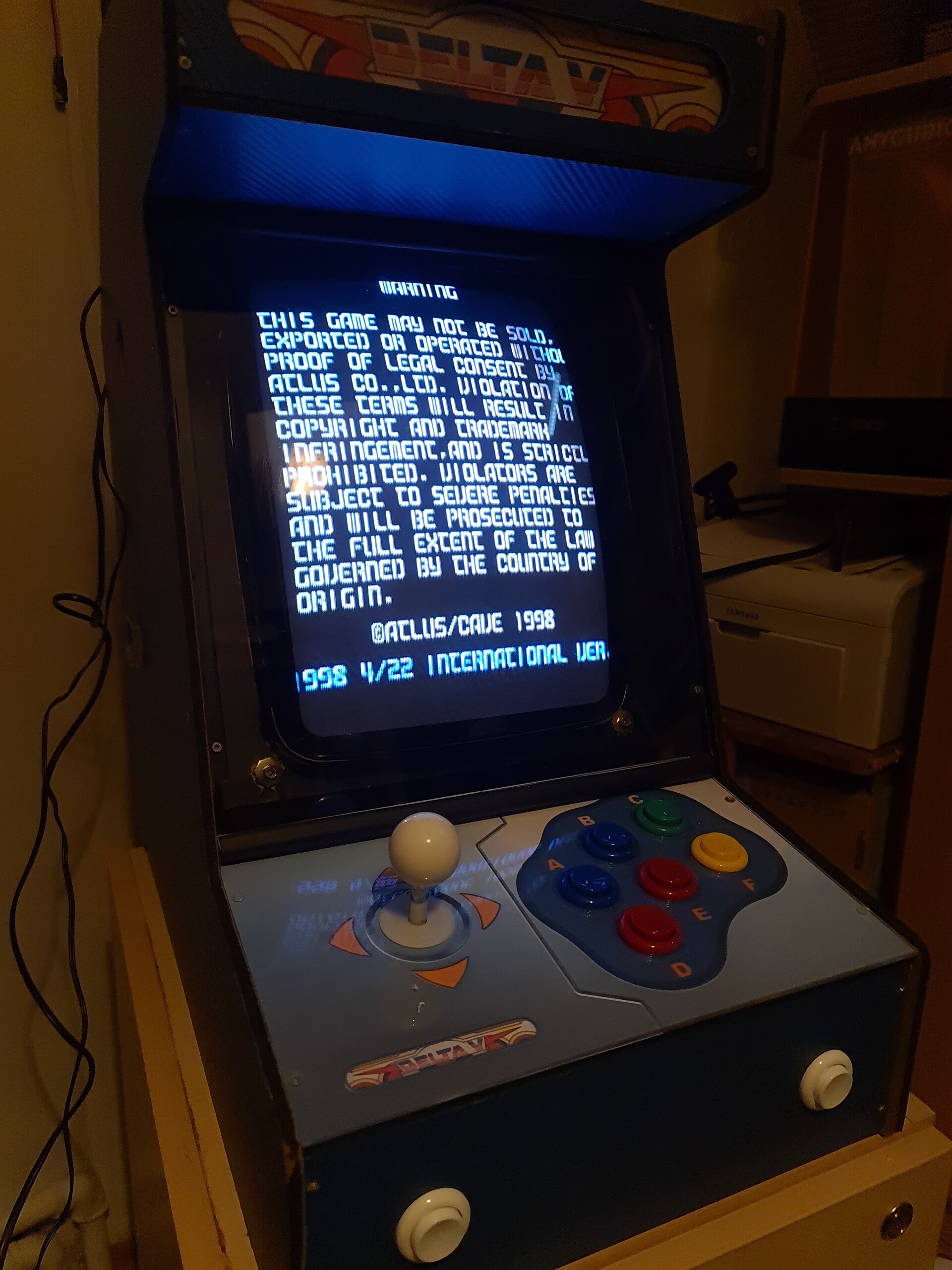
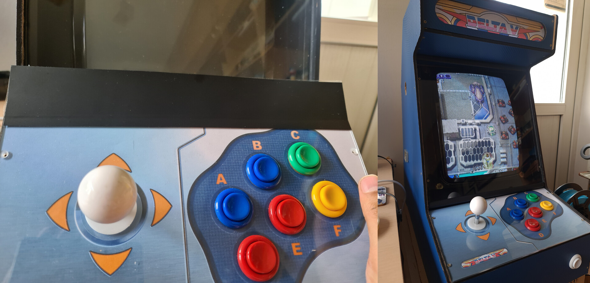
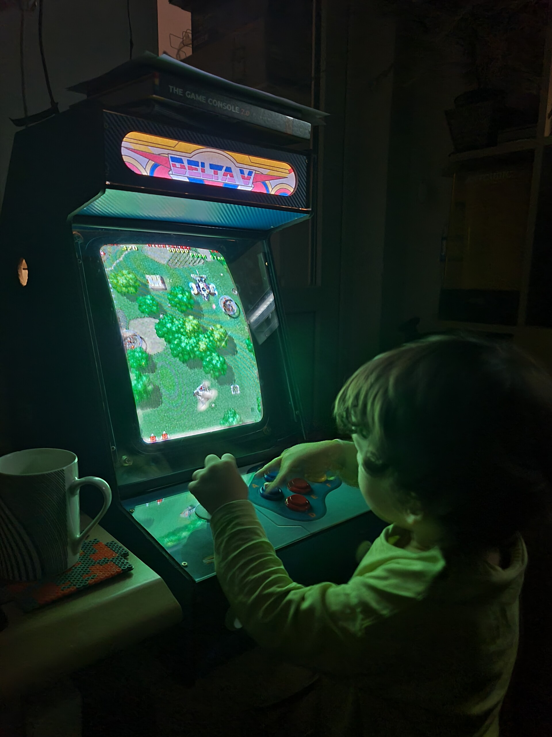
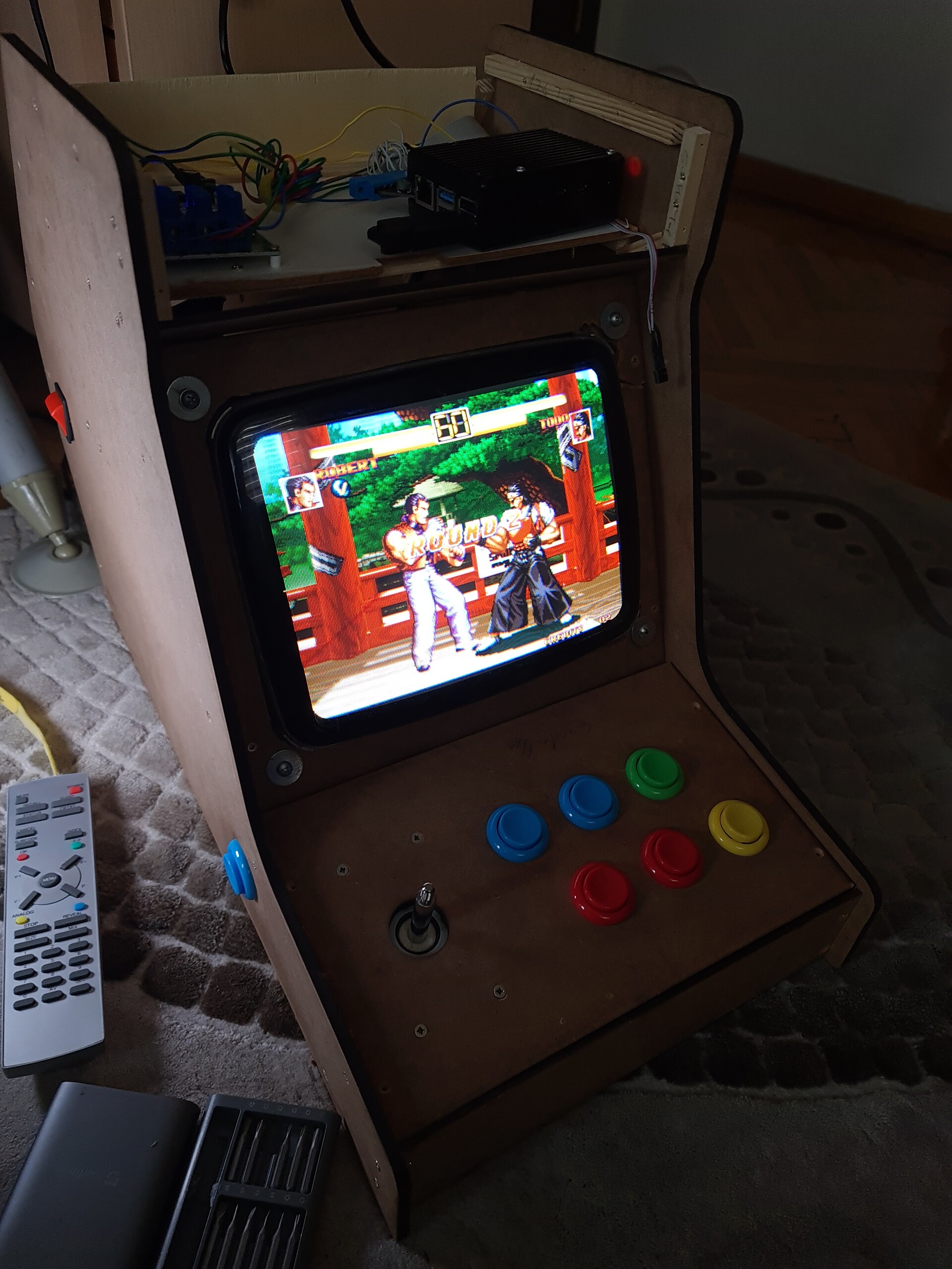
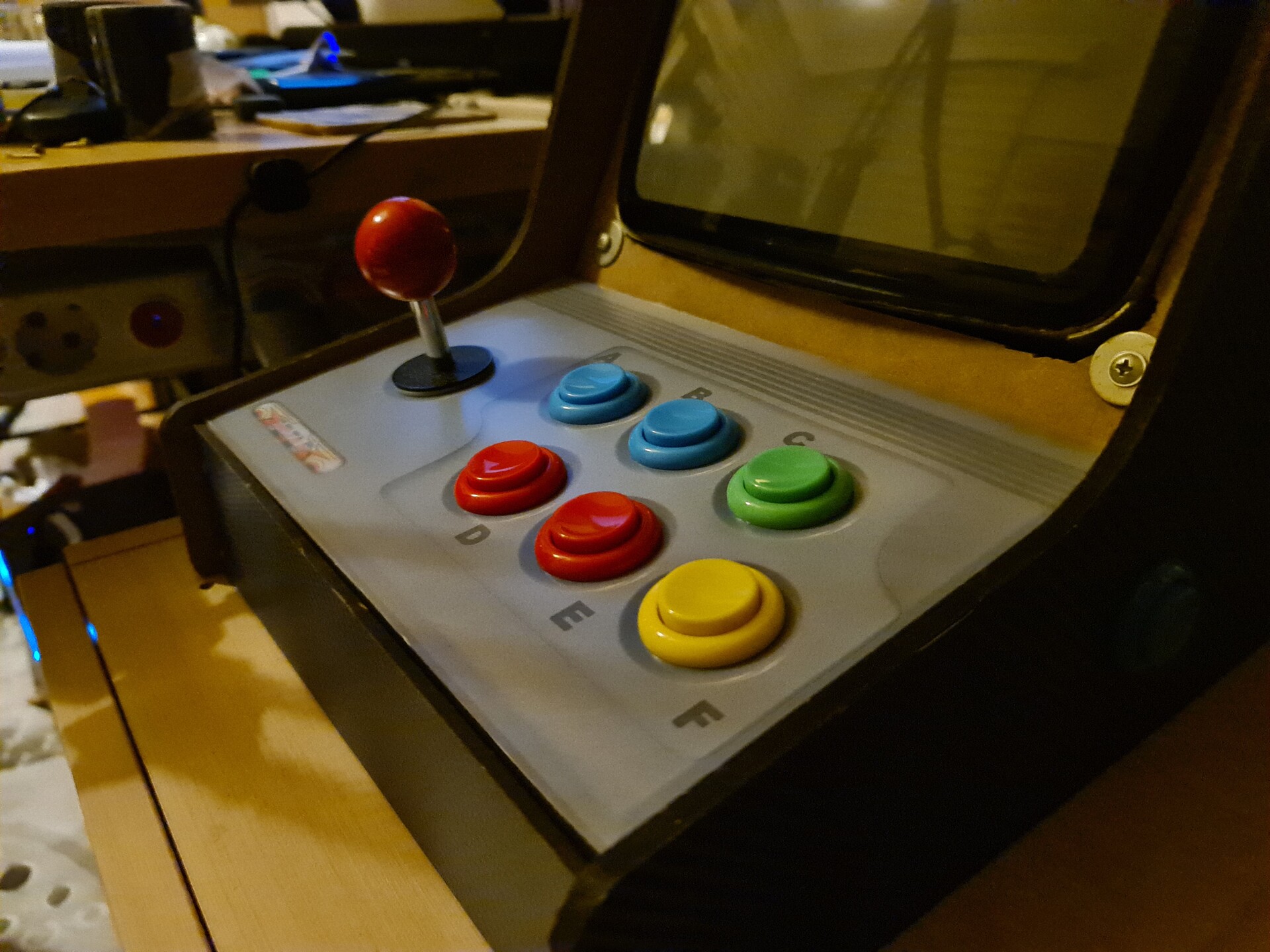
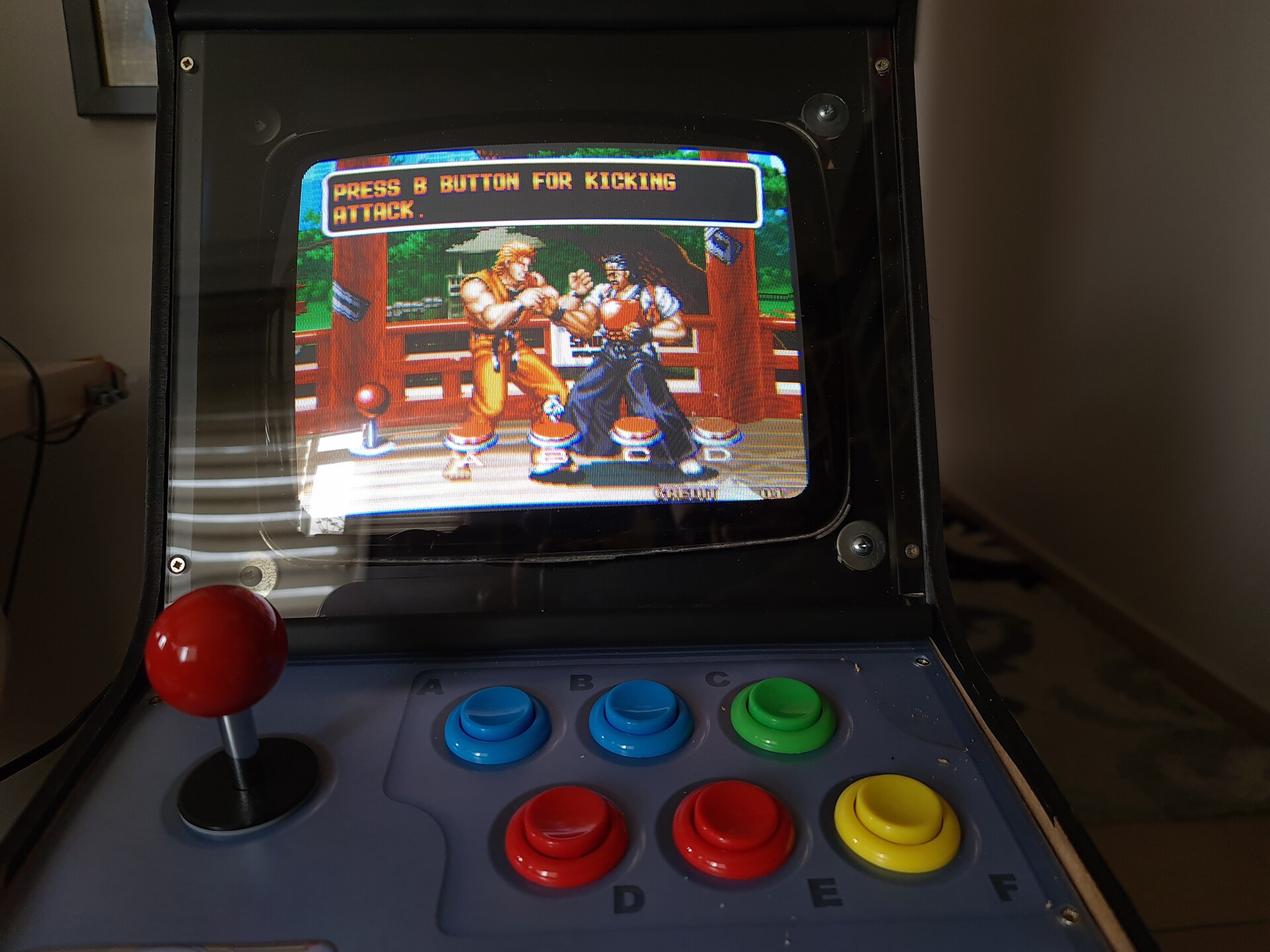
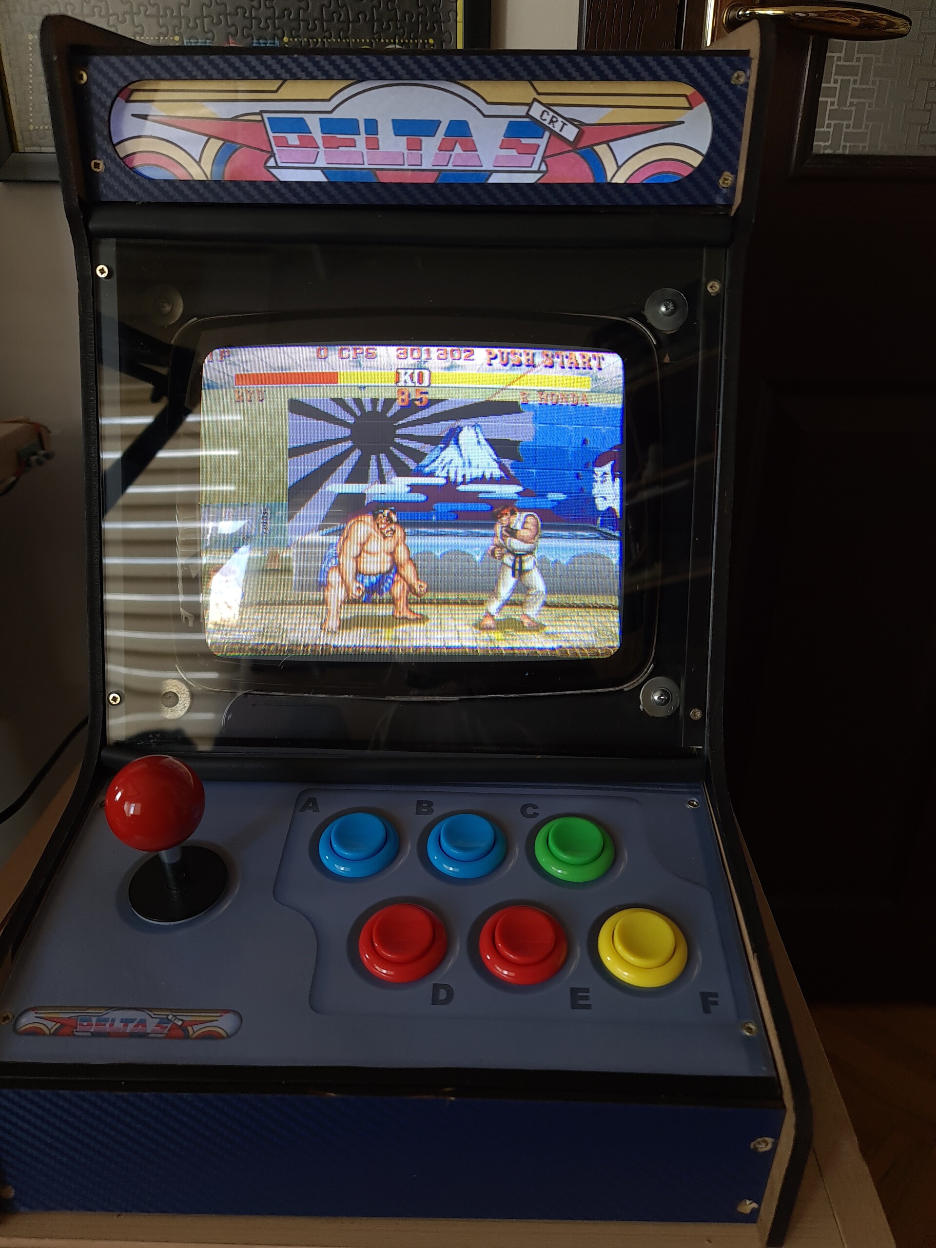
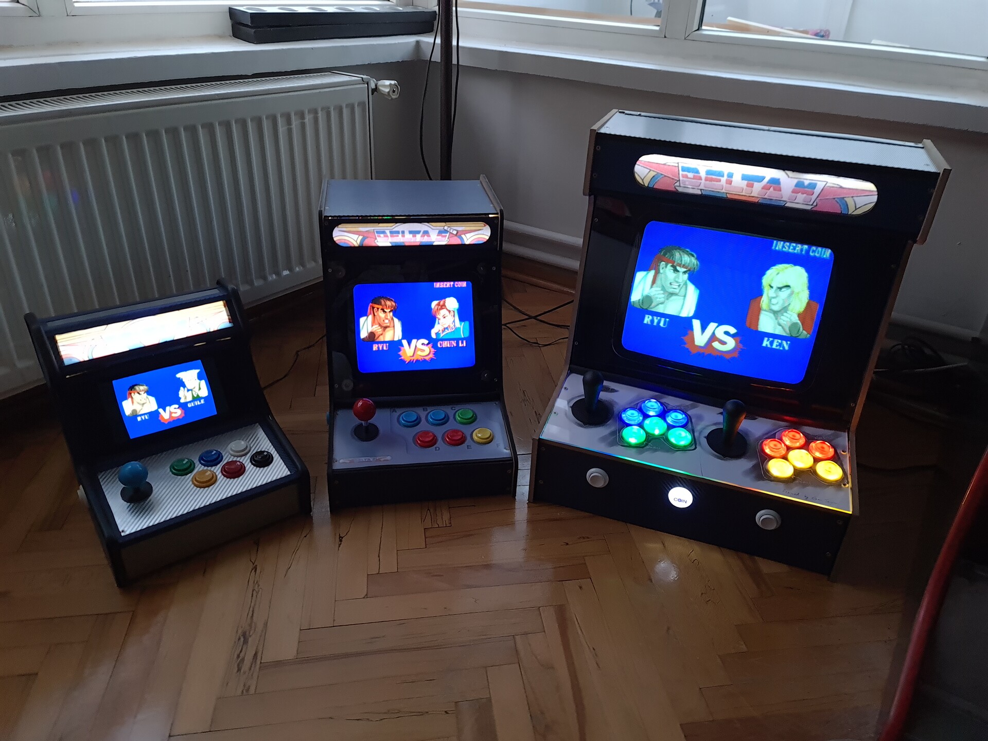
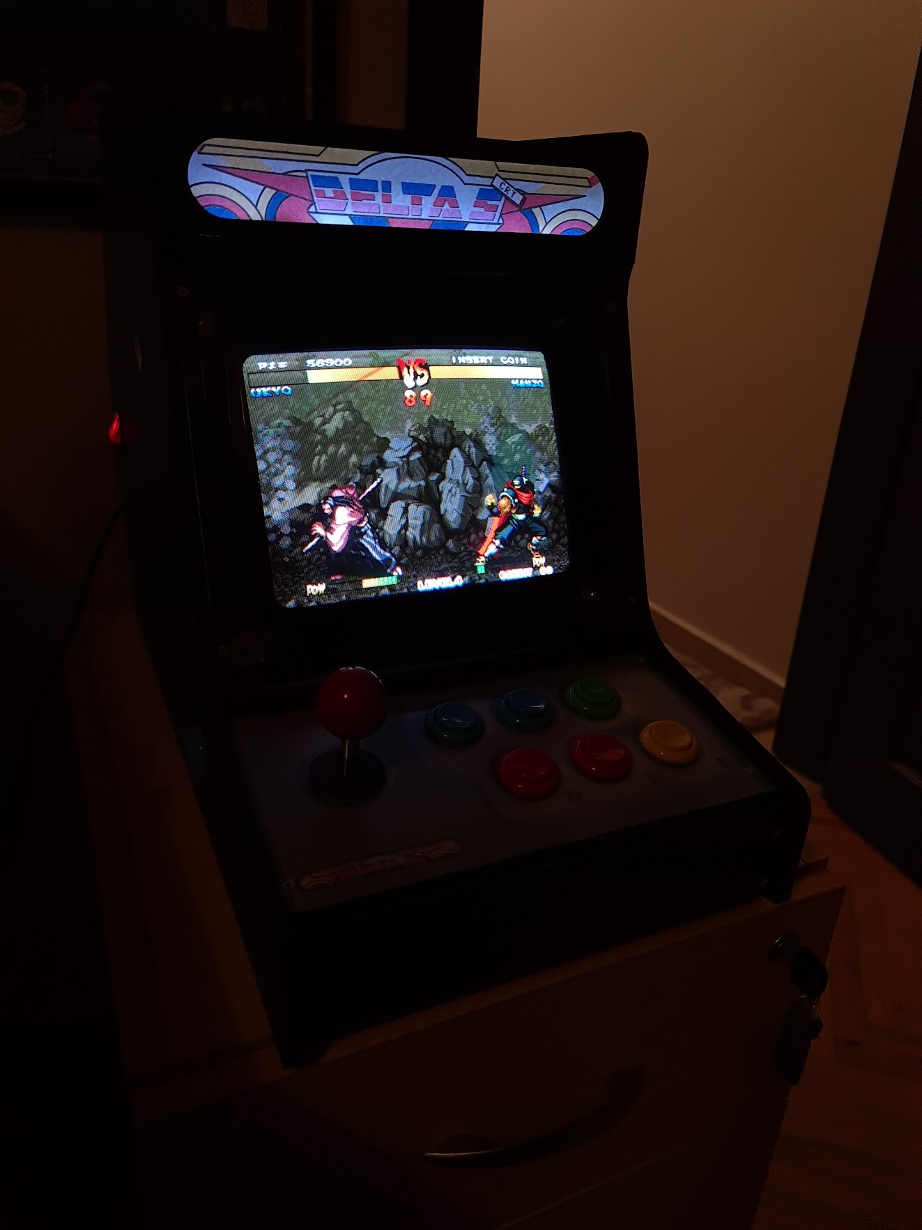
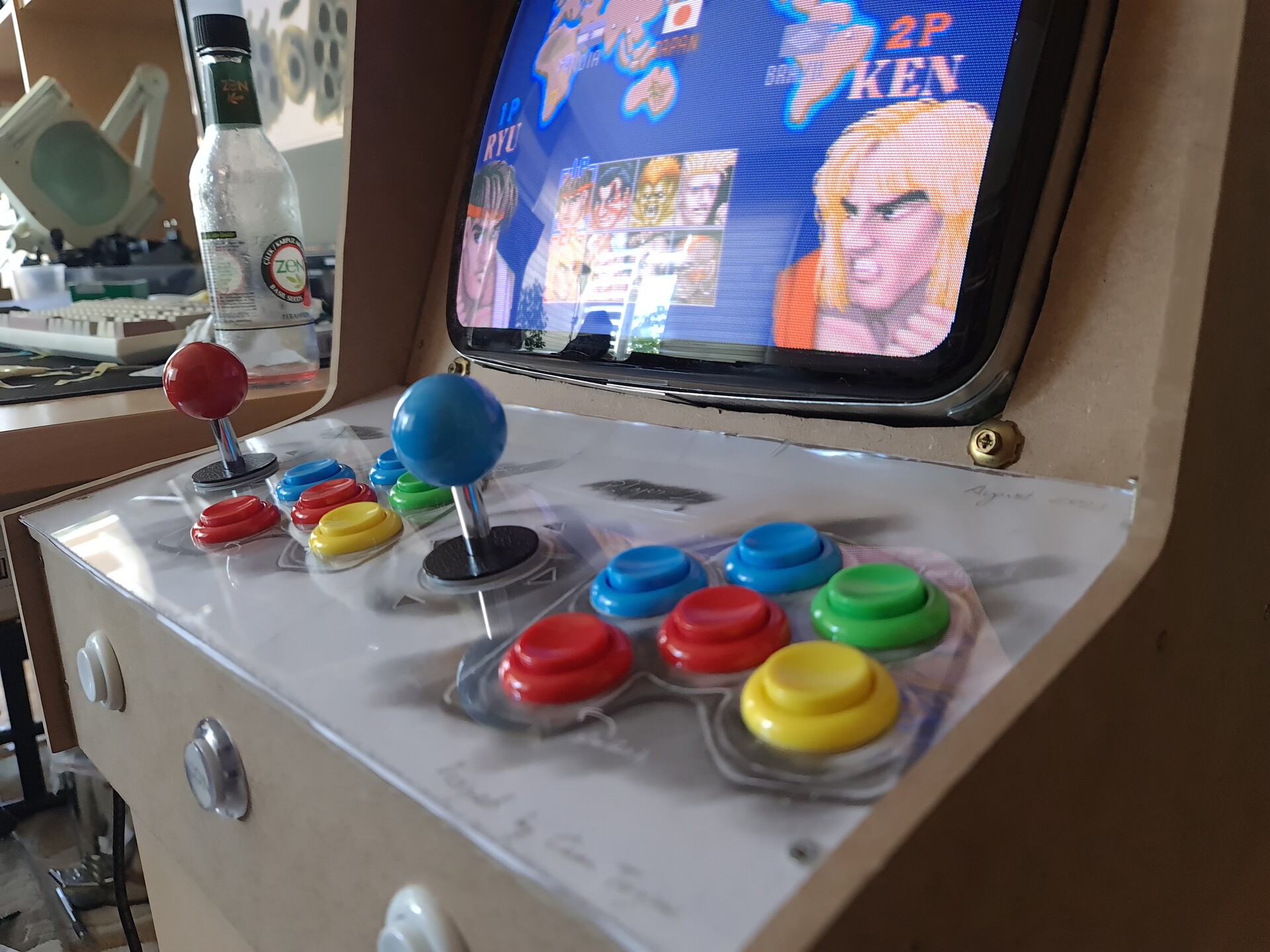
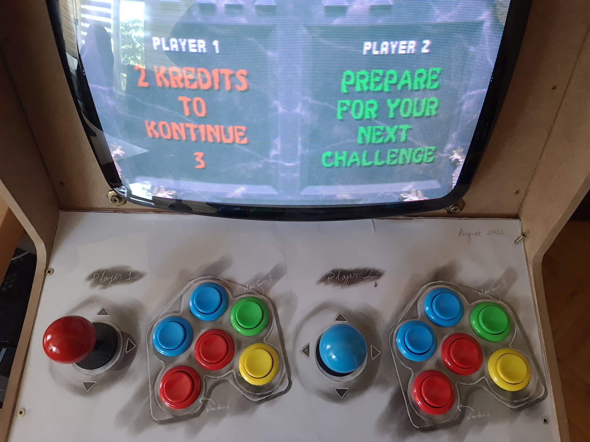
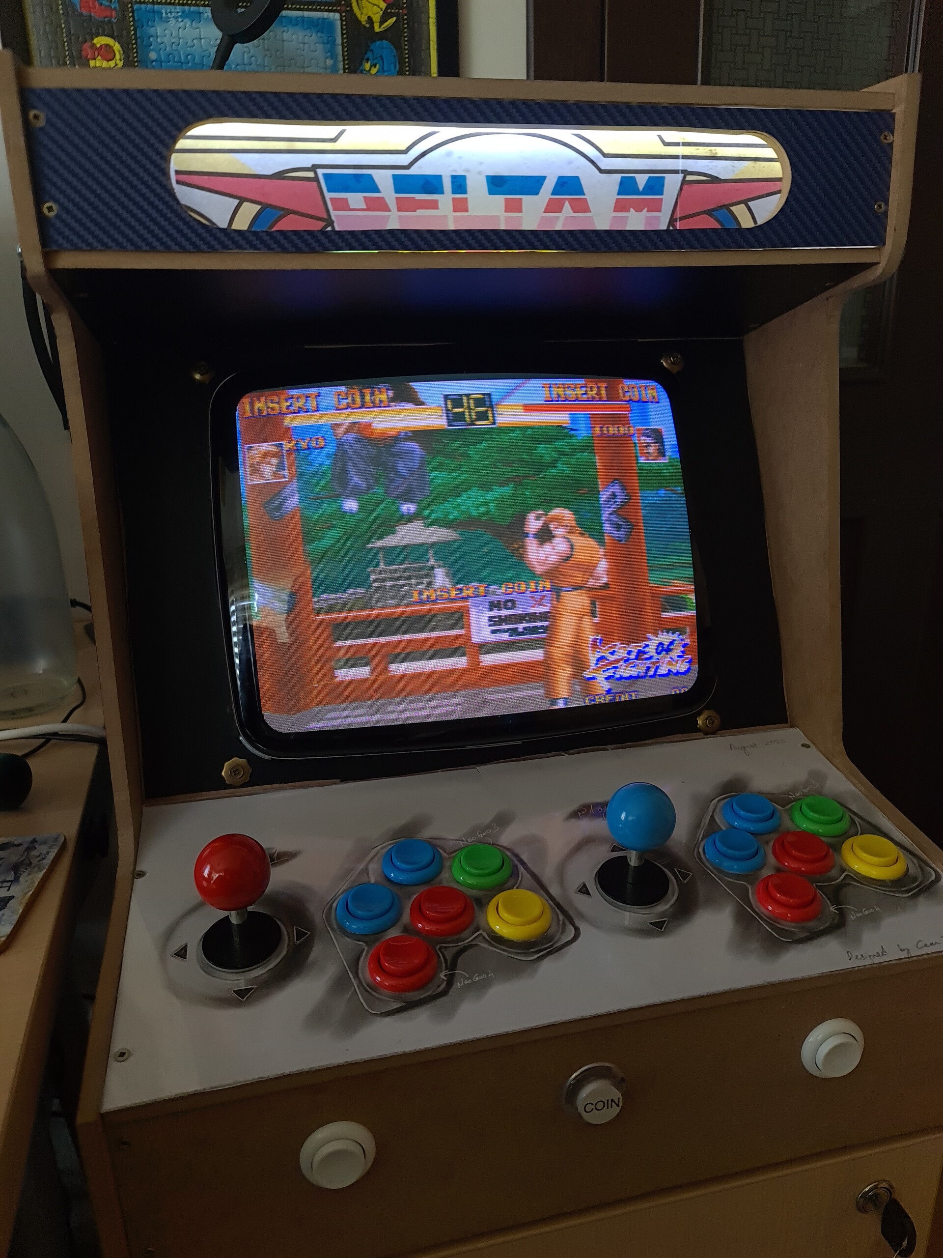
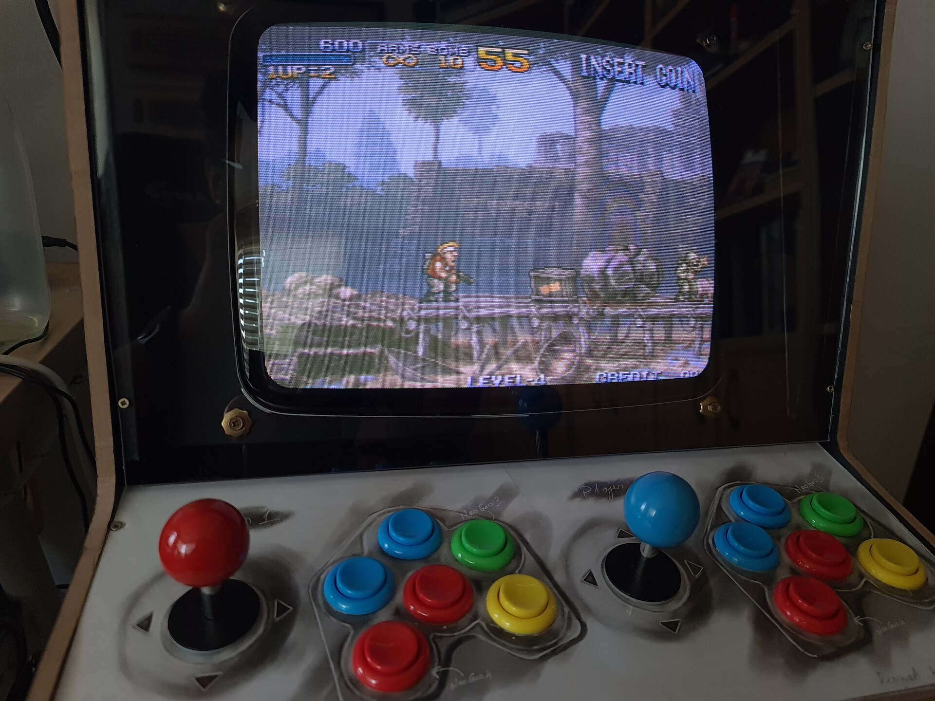
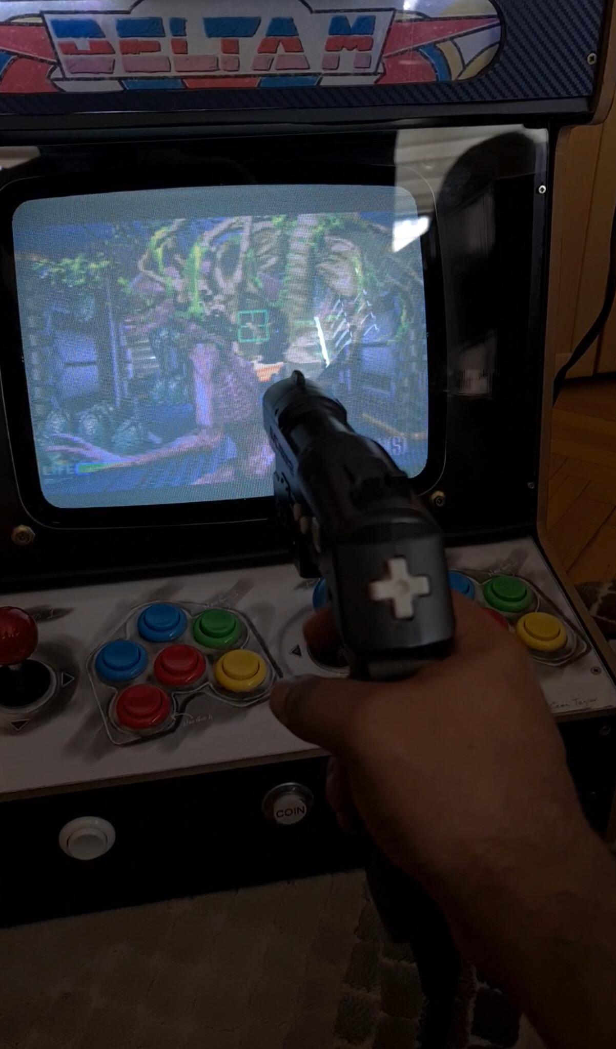
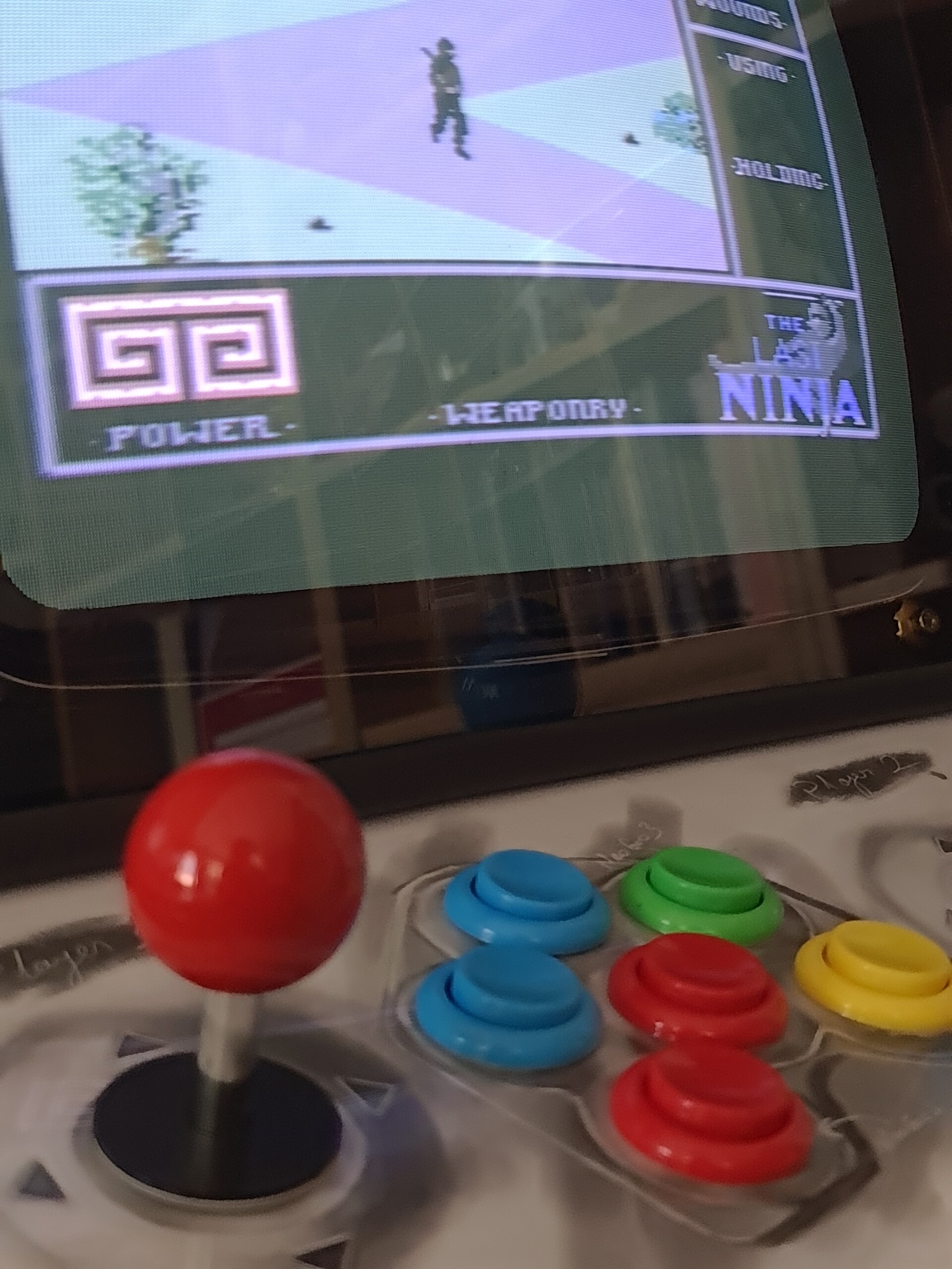
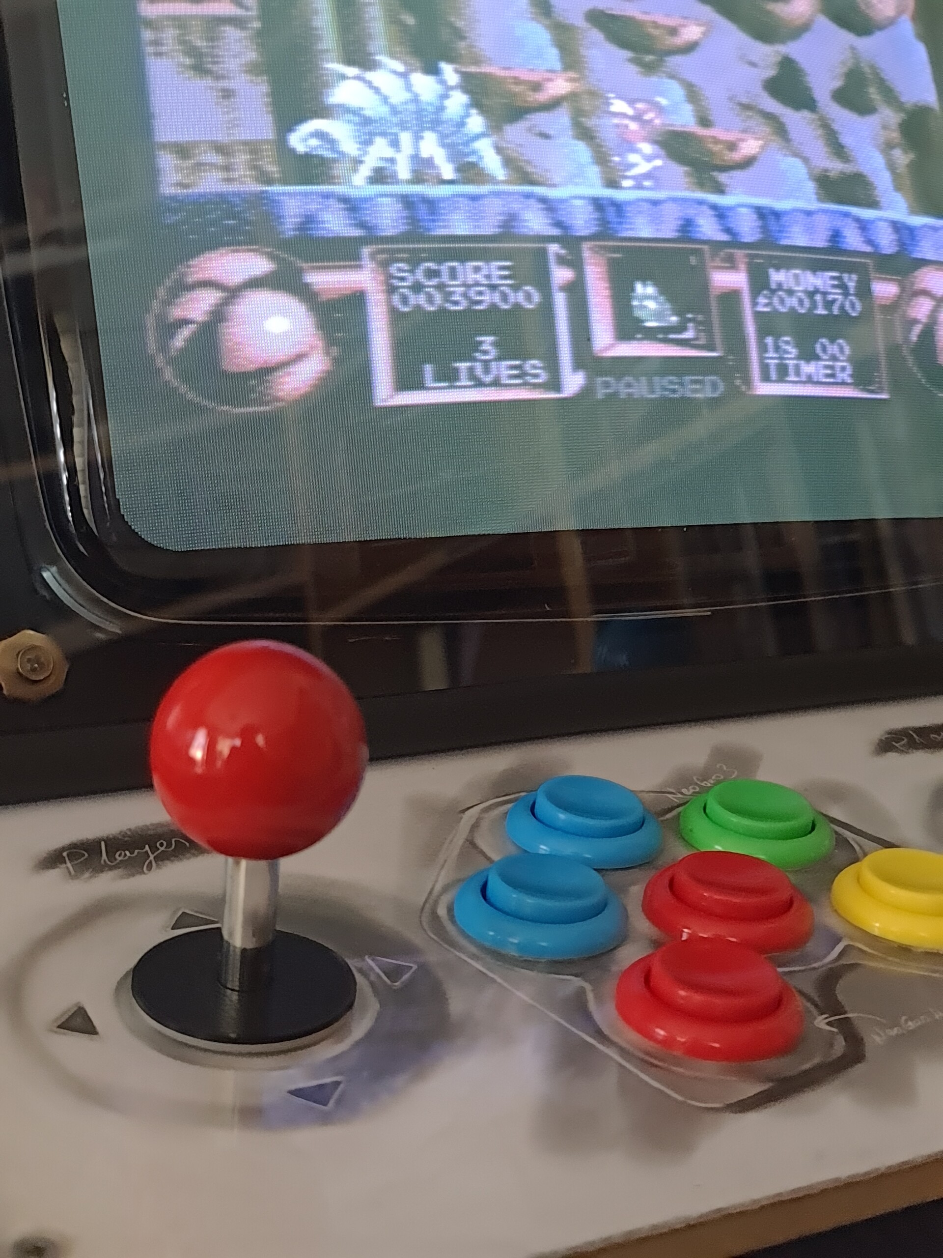
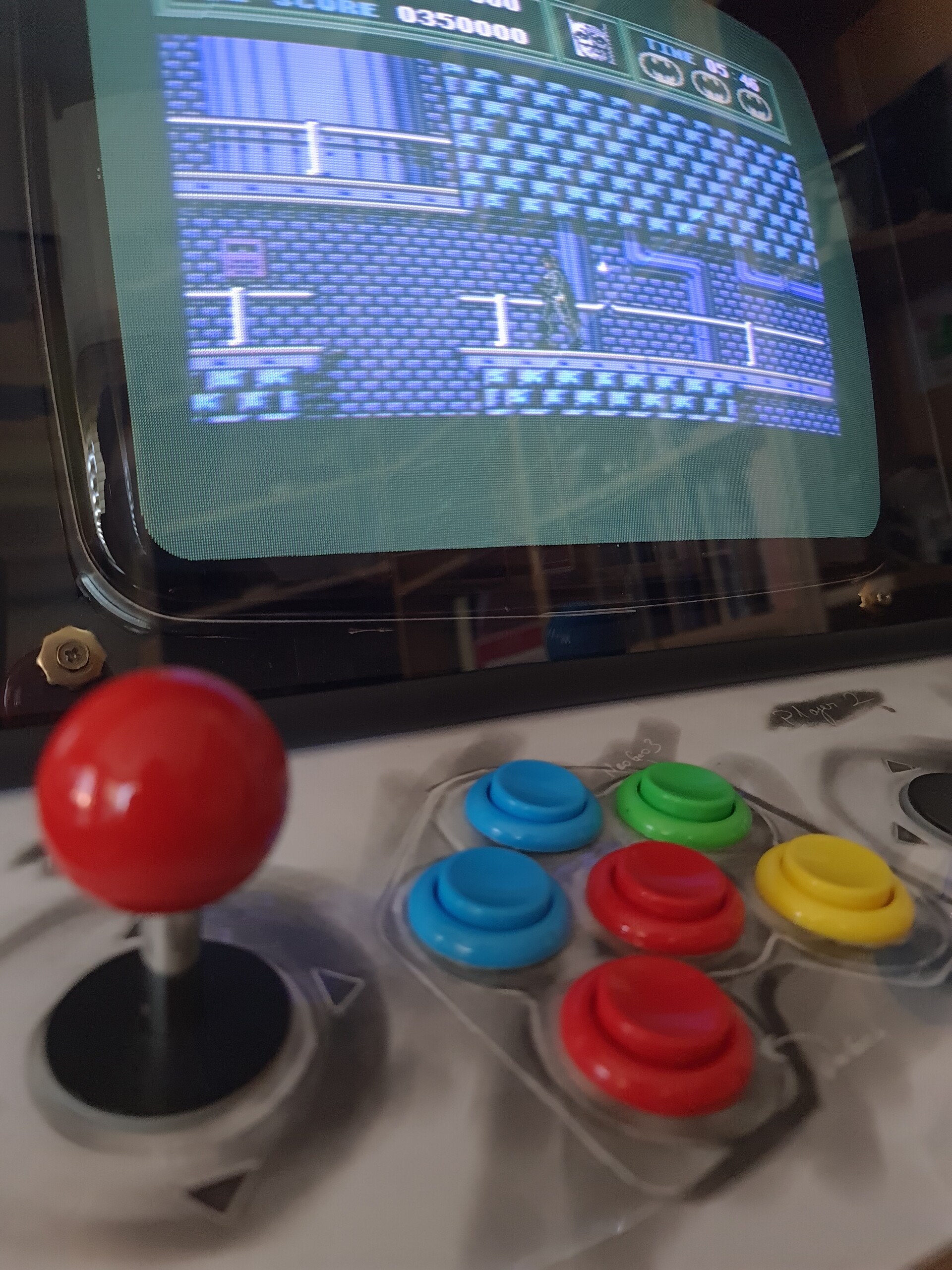
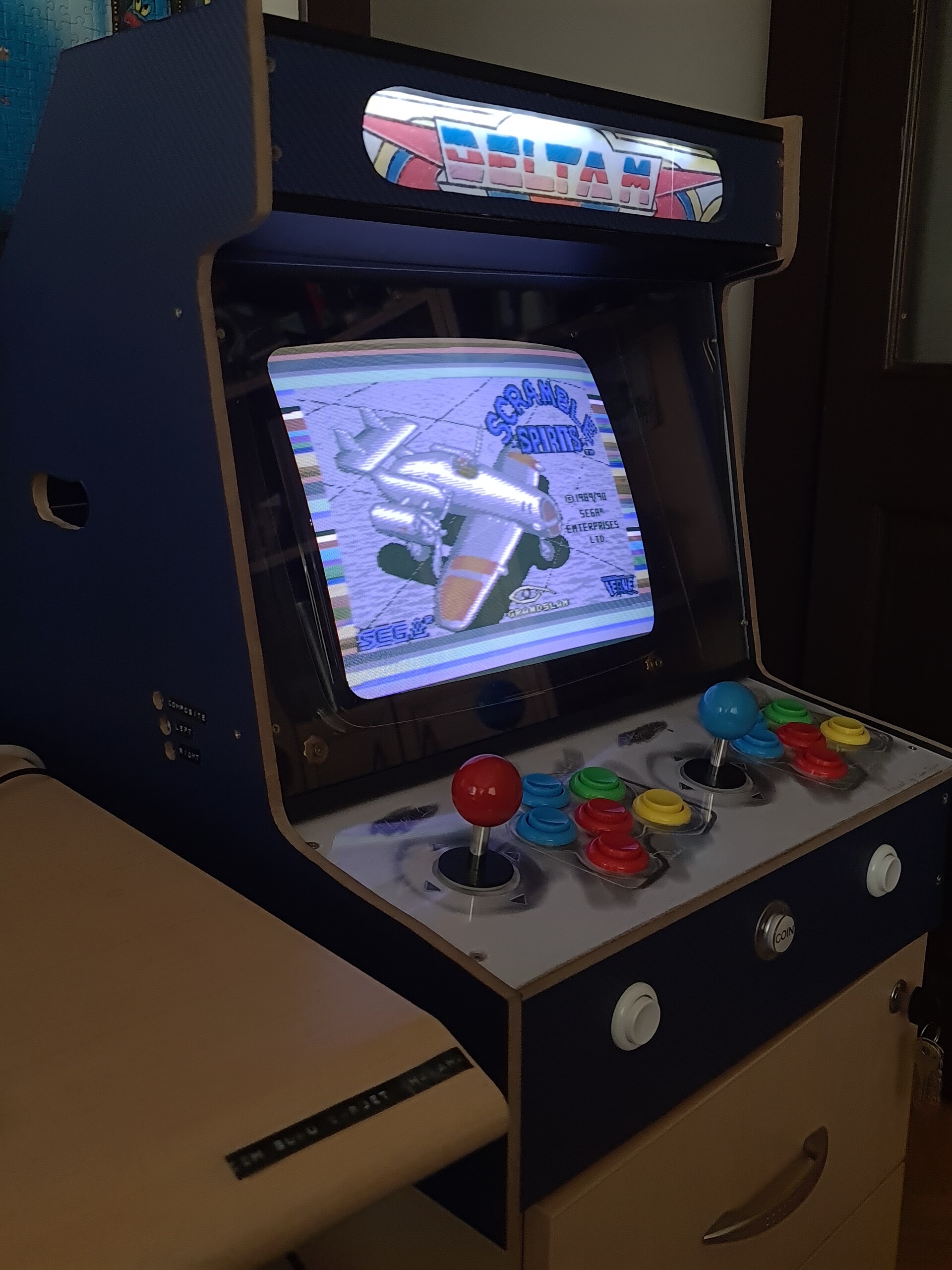
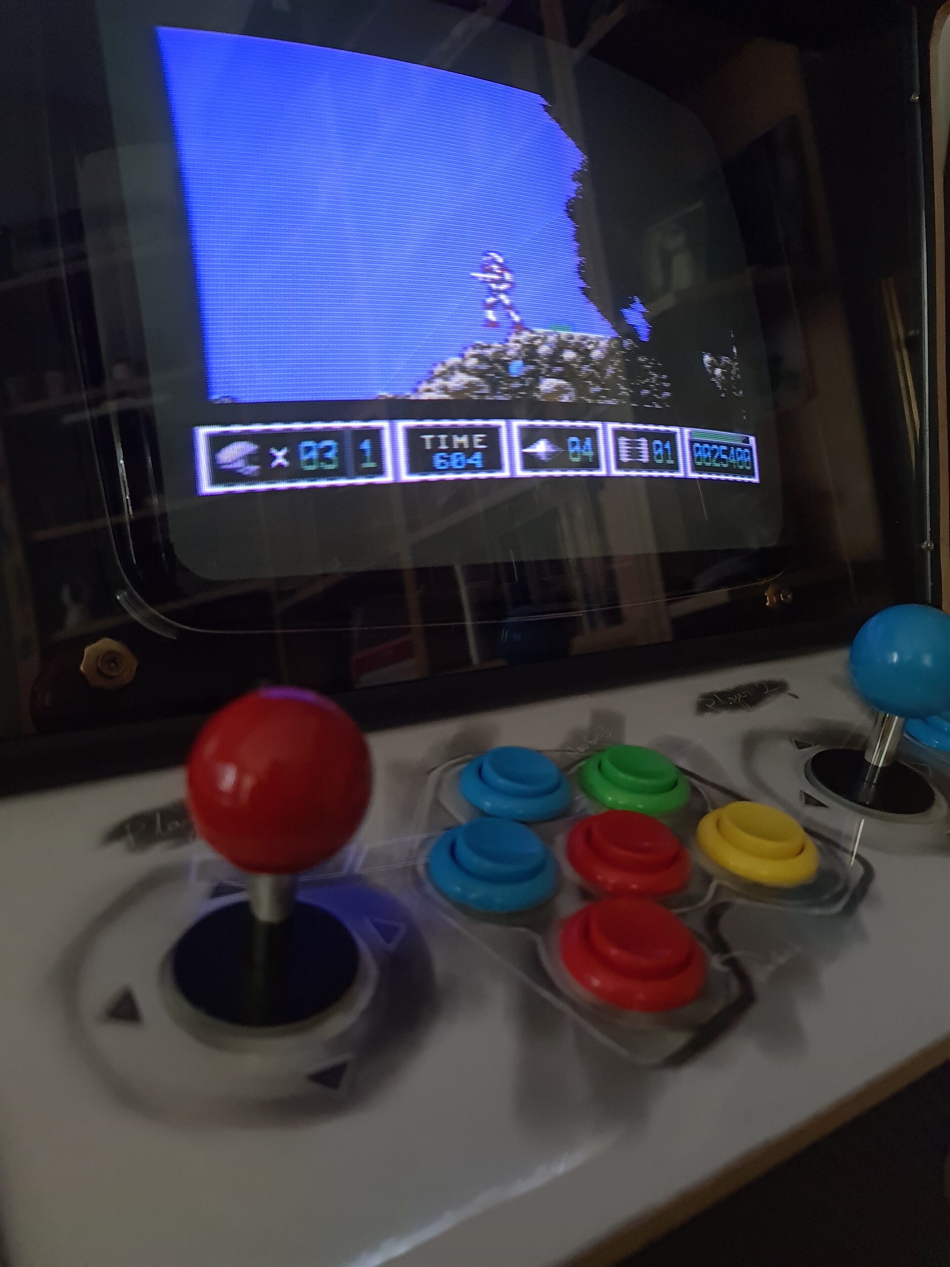
Now the controlers are ON!

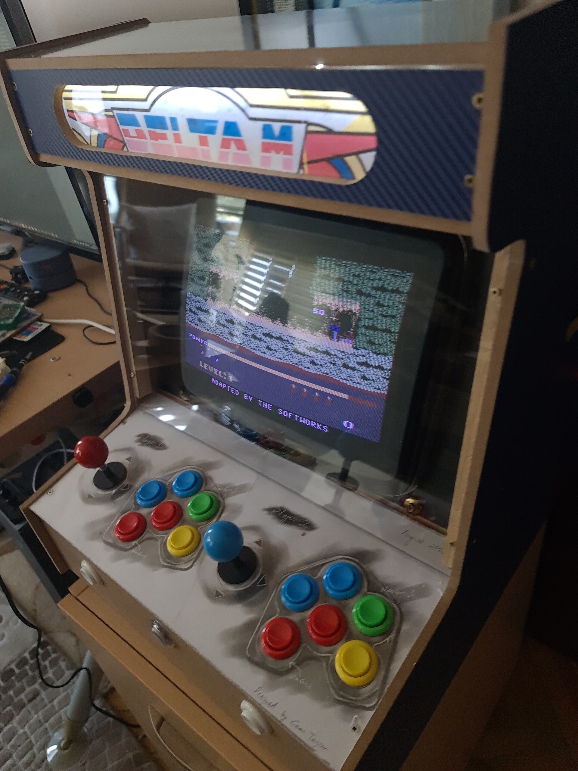
Let's play some Metal Slug!


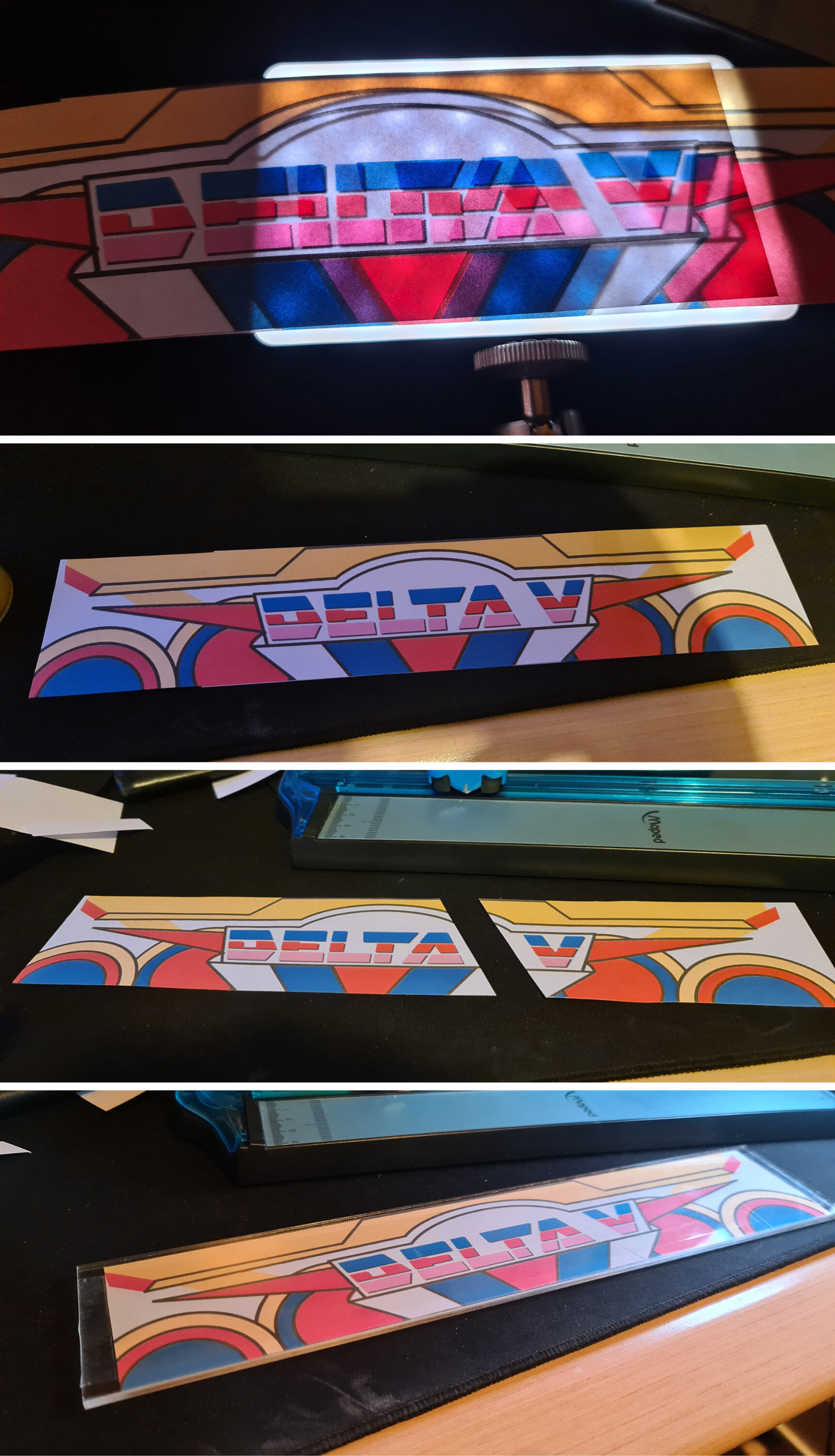
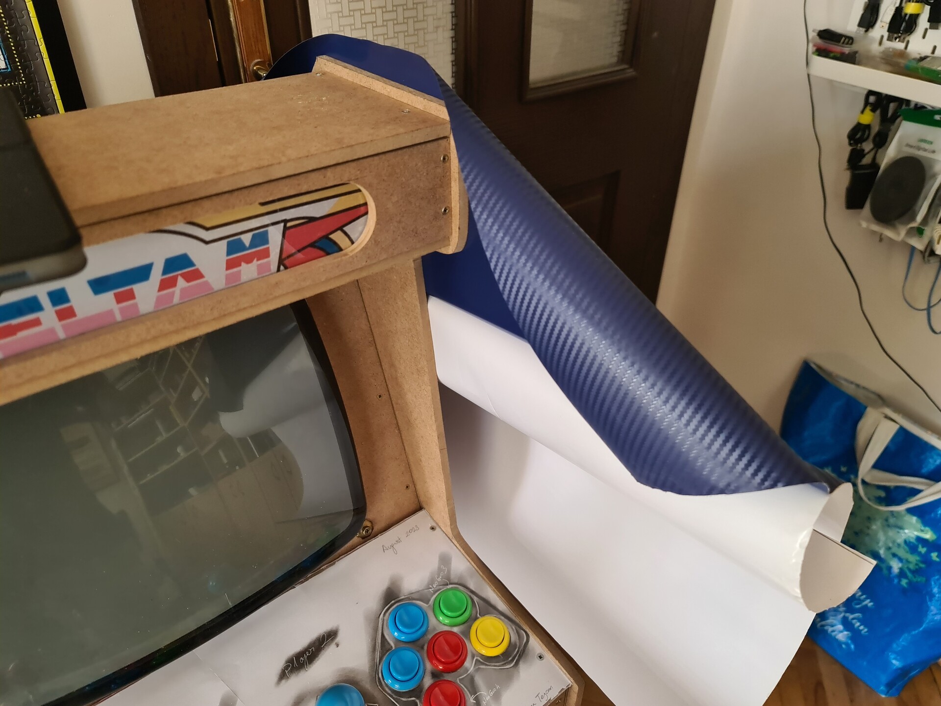
Now it's time for cosmetic details. See you on the next part.

P.S. This post was actually one piece. But Artstation gave some errors about the length of the blog post. You can check the 2nd part by this link:
https://www.artstation.com/blogs/blockmind/Y1gw/making-of-a-crt-tabletop-bartop-arcade-machine-part-22


My Arcade Cabinet Purchase and Modification Journey (Part 2)

Making Of / 22 August 2023

Hello! Previously I was modifying an arcade cabinet for the best way of using it according to my needs. Now this is the second part of the journey.

You can find the first part in my blog, and by this link: 
https://www.artstation.com/blogs/blockmind/wd1p/my-arcade-cabinet-purchase-and-modification-journey-part-1

1. Fixing the cosmetics on the Coin Slot

Coin slot has a removed plate on it. Possible that plate was having the shape of the section profile of the coins that used on that machine. That kind of coins were haing S shaped section profile.

Anyway, it was looking very bad, so I decided to make it look better. 

As a starter I used the existing blown rivets to hold the screws I'm going to add. I dirlled a hole through them with M2 drill by hand. 

Next I used M2.5 "Tap" to open threads on that hole.

You can see the threads inside.

And M2.5 countersunk screw driven very good.


I measured all the geometry around the slot to design a 3d printed frame on it. I used solidworks to model it.

I made some measurement mistake on the top left corner of the part but it's not so important for the mounting, so I keep it like that.

Screws didn't look good on the black part because they were very shiny. I made a partial "bluing" on the screws. That means I heated them and dropped into a cooking oil. That protects it from rusting and gives a black color which was the main purpose.

More info about bluing: https://youtu.be/5Sty5upsadY

And this is how it looks.

Insterting some coins.


2. Adding USB Extention Ports and Sync Port for Light Guns

Since there is also a Raspberry Pi inside the cabinet, adding USB ports outside the cabinet would be a nice touch to play 3-4 player games or, playing away from the cabinet with gamepads etc.

The other port that I wanted to add was the RCA port for the Sync signal of the CRT screen. This signal is important for the "light guns" that are used for playing gun games by tracking the coordinate of the screen where the gun is pointed. For that purpose I acquired 2 pieces of Namco Guncon 2 lightgun from Ebay.

These guns are connected by both USB plug and sync connector. Otherwise they don't work.

I used simple USB extenstion cables, but first, I needed to cut the front hatch of the cabinet. I drilled a hole, and used fret saw to cut the panel.

I designed a little part to hold the ports and 3D printed it.


This part is tightened by the help of the nuts at the back side.


And this is how it looks.

I also 3d-printed some hangers to put the guns on the cabinet. Later on I removed them but it was looking not bad :)

Now I'm able to play with the light guns but other important thing for that guns is they need high brightness on the screen. But that high brightness is not good for other games because this way screen lacks of good contrast and saturation. So, I needed a potentiometer to control the screen brightness easily without accessing the back door of the cabinet each time.  

So I soldered a paralled connection to the existing potentiometer of the screen controller board inside the cabinet and soldered a potentiometer to that cable. And fixed the new potentiometer to the back of the cabinet for easy access.

This is not a good looking installation but it's backstage. So I can live with that :D

And this is how it's played :)


Well, this is the end of my arcade cabinet adventure, at least limited with this cabinet... Thanks for reading, and see you soon!