Making of a 10" CRT Bartop Arcade Machine

Making Of / 17 February 2024

Hi everyone. A while ago I bought a second hand 10 inch CRT TV from a seller. Considering the size of it, it was looking great to make a CRT arcade cabinet with that one. 

  1. My Previous Cabinet Projects

Previously I made a cabinet with an 8" LCD screen. That was a portable, small, 1 player good cabinet. Only downside of that one was it has LCD screen, not a CRT. 

https://www.artstation.com/blogs/blockmind/PvdE/making-of-a-tabletop-arcade-machine

Next I acquired a 13" CRT TV and made a cabinet with that screen for 2 players.

https://www.artstation.com/blogs/blockmind/EgoA/making-of-a-crt-tabletop-bartop-arcade-machine-part-1-2
https://www.artstation.com/blogs/blockmind/Y1gw/making-of-a-crt-tabletop-bartop-arcade-machine-part-22

The new one is the middle one on this render:

2. 10" TV and the Idea

The TV a got is a 10" Schaub Lorenz with a SCART input. I heard the name for the first time.

The most important feature of this TV is that it is a multy-sync TV that supports refresh rates  from 50 hz to 60 hz. This is important since many arcade games have variated screen refresh rates like 54hz, 57hz etc.

Since it has a small size, the phospor pattern is so visible but as a good news, scanlines are less recognizable. 

3. Making of the Case

Before getting into wood panels (actually I use MDF panels) I disassemblied the TV and quickly measured the outer dimensions of the CRT tube. This way I made a quick design with Solidworks to fetch a cut list.

And I exported the DWG files for the panels and ordered a laser cut service from a local advertisement company.

Once I received the cut panels, I realized that TV mainboard can't fit under the tube, so I placed the motherboard to the top on my 3d design (which was a unnecessary doubt since I see that it can fit, later).  

4. Constructing the Cabinet with Panels

I bought some screws and laths to connect the boards. Laths are the best mounting aid for the MDF panels. I measured and cut the laths and placed them on the side panel first.

I used my hand drilling machine to drill holes and tighten the screws.

So after fixing the fisrt set of laths, I placed the panels and hoped that I didn't made a mistake on my quick design :)

Since I needed to fix the laths on the both side panels, I needed to fix them on the exact opposite position. Quadrant is a useful too for matching the angles on both sides. I drew lines for the positions of the laths.

After fixing all the laths, I drilled and screwed the panels one by one.

Since I couldn't be able to draw the hole for the tube hole, I needed to cut it by hand using a jigsaw. I made a terrible job but I was confident that I can cover the problematic gaps with sticker vinyl.

Finally I managed to fix the tube to the frame.

Next, I made a platform for to place the raspberry pi and jamma connector.

5. Electronic Touches and Finalization

Since I'm using a TV, I need to user the remote control of the TV to adjust image etc. It's needed to place the IR sensor of the remote control, because the mainboard of the TV will be placed at the bottom back side of the cabinet. So I desoldered the sensor and soldered a cable to place the sensor at the top of the cabinet.

After moving the sensor, I soldered cables for the connector part. I used a 40 pin connector to detach the controller panel anyhtime in future for maintenance purposes.


I used a DC voltage stepdown module for reducing 12V DC voltage to 5 volts. This way I can use both 12V and 5V DC for jamma to operate raspberry pi and the speaker amp circuit.

I use RGB-Pi Jamma circuit (https://www.rgb-pi.com/) for emulating games. RGB-Pi is the perfect device with its own software which allows me to play the games at their original refresh rates. It works great with multisync CRT screen so this way TV shows the smooth scroll gaming on specific refresh rates. Classic arcade emulators run at fixed 60hz / 60fps. This way games that designed less than 60hz runs faster than their original way or you get screen tearing, frame skipping or other issues on emulation.

I placed the power switch to the left side of the cabinet by cutting a hole for it. I connected the 220 AC input the that switch and distributed that voltage to a 12v DC adapter and the TV itself.

Works fine! So I closed the back panels and moved on with the covering the panels with vinyl folio.

I got some spare sticker folio from the last project so I applied it to the side and front panels.

I used the previous design that I made for the LCD cabinet and put a CRT label to the top. Printed and applied to the plexiglass I have for the marquee area.

For the controller area, I used Substance Designer to make a procedural panel design and applied a shading for it with PBR render node within the software.


I fixed the plexiglass to the marquee window with hot glue. And then I used double sided tape to fix the printed out paper over it.

I cut the holes with the knife on the controller print-out. I cut the same holes over the PVC plate so the paper won't be affected by the hand sweat or dirt in time of usage.

This is how it looks so far.

There is a screen glass I ordered for cutting and it will be placed over the actual screen. But before fixing it over the CRT screen, I needed to cover the area around the screen with black sticker vinyl.

Since I badly cut the frame around the screen, I applied some pvc sheet over the gaps between the screen and the frame by double sided tape.


After that, I covered a lath with the same black vinyl and fixed it to the plexiglass with screws. And then I drilled and screwed the laths that attached with the plexiglass to the cabinet side boards.

I had some rubber corner protection stripes that sold for protecting children to get injured by the sharp corners of the home furniture. I fixed that stripes to the screen glass edges.

Looks better!


A quick tesy by my son.


Meanwhile the study room is devastated.


As some final touches, I added an LED strip for the Marquee lighting.

For the sound system, I had a spare speakers that I had by my old broken hometheater system. I used center speaker set of it and fixed the speakers to the back board.

And the cabinet is ready to use. I put all 3 pieces I made so far side by side.

Hope you like the result, and as always, thanks for tuning in.


Making of a CRT Tabletop / Bartop Arcade Machine - Part 2/2

Making Of / 24 August 2023

Let's continue from the previous part. you can find the first part by this link:
https://www.artstation.com/blogs/blockmind/EgoA/making-of-a-crt-tabletop-bartop-arcade-machine-part-12


6. Texturing the Cabinet

Before getting into cosmetic details, it was urgent to add another layer over the controller panel, because hand sweat was not good for MDF. I decided to use a translucent plexiglass I had over a while, so I drilled the same holes on it, to use it as an overlay.

Since I was using a translucent plate, I decided to add a personal touch to print and apply it between the MDF and the Plexiglass. I exported this sketch and made a drawing with my good old Samsung Tablet.

I printed out the sketch top two A4 paper and align them. Next I cut the holes and then mounted the controls back.


Now we got a nice shiny look.

Next, I cut a slot hole on the marquee board and mounted another translucent plexiglass behind it.

I printed out another visual. I revised the "Delta" brand and called this Bartop Cabinet as "Delta M" which stands for medium size :) I also added LED lights to lit the marquee part.

I revised the same design with a hand sketch look with my tablet as well.

Now I used spare foils that I had from the previous cabinet and applied to the cabinet starting from side surfaces.

After covering the side surfaces, I moved on by covering the frame of the CRT screen with black foil.


Now it's time for applying the glass in front of the screen. I used another plexiglass for that. I added 2 wooden slats to the sides. Also I drilled holes on plexiglass and fixed it with screws.

Looks shiny!

Now it's time for making everything black inside the outer glass. I started by using black sticker foils on the slats, and then the inside surfaces.

The difference is remarkable!

And I added a rubber edge corner to the screen glass to make a better intersection with plexiglass of the controller glass. 

7. Peripherals Add-On

As a final touch, I decided to add the following:

  • 2 ports USB extension
  • Video Sync port for Guncon Lightguns
  • On/Off Switch for the Marquee Lighting
  • On/Off Switch for the 12V adapter, so it cuts off the jamma connection (This is needed for using composite input, otherwise TV can't process both signals from composite input and the jamma,/scart)

For that purpose I used USB extension cables and a female RCA port and 2 pieces of switches. I also 3d modeled and 3d printed a part to hold these switches and ports. 


Because of a minor design mistake, I used a 3d print finishing tool (it's more like a soldering gun with a flat tip) I melted part to comply with the cables.

Finally I mounted the part to the back board of the cabinet. And used my labeling machine to stamp some labels.

With this add on I can connect Guncon 2 lightguns to play gun games, like this:

You can check this Youtube Short: https://youtube.com/shorts/yp4mpSSyPnc

I'm also attaching some family photos of Delta series. Delta II, Delta S and the new member: Delta M.


8. Conclusion

It was a great experience to build this cabinet. What I love with this cabinet is like these:

  • Screen size and the overal size is really good/compact. 
  • It has CRT, which is the best experience with the "pixels."
  • Smooth scrolling emulation with RGB-Pi in precise on frame rate specific for any game or gaming system is amazing. This makes you perfectionist :)
  • System also can emulate other 8-bit and 16-bit systems like Megadrive, Commodore 64, Snes, Amiga, even Playstation.
  • Jamma port allows me to use origibal arcade boards to use on this cabinet.
  • Composite input allows the system to be used as a simple monitor for attaching any old-school console.
  • 2 or more player can play games together with additional USB ports.
  • Guncon2 Lightguns are supported to play virtua cop etc.

Thanks for reading this, I hope you like the process, and I hope it can be helpful to you on creating your own arcade system. See you soon.

I'm adding some random visuals of the cabinet with different systems and games. Enjoy & cheers!


Making of a CRT Tabletop / Bartop Arcade Machine - Part 1/2

Making Of / 24 August 2023

Hello everyone, recently I made another Bartop style arcade cabinet with a CRT screen. This was a real fun project, but the best part is I made it in home by the tools I have. So you can consider it's most part by "DIY".

Bartop Arcade Cabinets are roughly more like a trimmed version of upright (classical) cabinets. But they are also designed with smaller screens so the size is smaller as well. You can put them on a table to play. I made an LCD version with one player controller previously. You can check that previous project by this link:

https://www.artstation.com/blogs/blockmind/PvdE/making-of-a-tabletop-arcade-machine 


1. Starting Point of Designing the Cabinet

1.1. The Screen

The main purpose of this cabinet was the "Premier" branded CRT TV that I saw in the house of my mother-in-law. It was a 14" CRT TV that show the pixels in a very good way. Also that TV supports refresh rates from 50hz to 60hz. And one the best thing about that TV was that it aligns screensize automatically, I don't know how. 

That TV made me think of creating another bartop cabinet by using that kind of CRT screen since it's small, but had enough size to show the pixels and games.


1.2. The Emulator and The Hardware

Another component that I had was an "RGB-Pi jamma hat" that can be used on Raspberry Pi devices to emulate arcade games. You can purchase different types of RGB-Pi products by this link: https://www.rgb-pi.com/

Normally if I had a RGB-Pi Scart instead of RGB-Pi Jamma I could connect it directly to these TVs but since my connection type is JAMMA then I needed to convert the jamma signal pinout to scart pinout. 

The best thing about these devices, they have a special software that compatible only with this hardware that runs the games in various refresh rates fixed to the original rate of the arcade game that you play. This part is the real tricky and one of the most important part on arcade game emulation. Because with modern equipments, we're playing those in a wrong speed. Every arcade game back in time had a specific refresh rate. Here are some examples:

  • Street Fighter II - 59.637405 Hz
  • Shadow Dancer - 57.230000 Hz
  • Mortal Kombat 1-2-3 - 54.706840 Hz

Consider these values as FPS of those games. But once you play those games in a PC, PSP, PS Vita or Retropie etc. you have a fixed 60 fps refresh rate. Thich means for the sake of smooth scrolling, emulator shows more frames than the actual framerate of the game. you play Mortal Kombat 9.6 percent faster than you used to be in 90s. Shocking, eh? Check this video.


Original refresh rate can only be achieved on a proper CRT screen with a proper sync signal which is generated by a proper raspberry pi device with a proper emulator. So my electronics setup is formed. 

2. JAMMA to SCART Conversion

Only problem was that my RGB-Pi hardware was JAMMA version. So I needed to make a convertion from Jamma to Scart. Because SCART is the easiest and the best connection for the TVs which is analog RGB.

I followed this two diagram and applied it between a jamma connector and a female scart connector. 


Source: https://www.mortaca.com/rgb-pi/wiki/index.php?title=RGB-Pi_JAMMA_Installation/en

Source: https://www.mortaca.com/rgb-pi/wiki/index.php?title=RGB-Pi_PLUS_Installation

Pinout is pretty easy. Also the Jamma Connectors need to have both 5V and 12V input. So I used a LM2596 DC-DC step down module to output both 12V and 5V through a single 12V adapter. 

After testing the pinout, I added 4 potentiometers to adjust R G B channels for better picture and adjust the Sync signal for for supporting different arcade systems. After that I designed a case for that little adjustment board where I also added a USB port to connect additional devices in the future.


When I was testing this piece, I accidentally burned the IC on the RGB-Pi circuit. That IC was an amplifier for the sound channel. But this is only needed if you connect the cound channels on a blank speakers. Since I was connecting my sound output to a TV, and the TV has it's own amplifier on its board, I just shot circuited sound channels directly to sound pins of the Jamma edge connected, which means I bypassed that burnt amp IC. 

3. Acquiring the TV

Now I had a fully functional convertion cable but I needed a TV. I checked the second-hand seller websites and found a cheap 14" CRT TV. The brand was the same, but the product model was different than the one my relative had. 


Look at the production date, it's May 2005! Which is very late for this kind of TVs I suppose!

4. Tests and Final Preparations

I tested the TV with my Jamma to Scart cable, and it even works with the original Neo-Geo MVS arcade board!

Meanwhile I bought an aluminum case for the Raspberry Pi 4 1GB version to work as a cooling system. I don't like fans, since it's not exceeding 55 °C with this case, I prefer using it like that.


4. Designing the Cabinet

As a starter, I disassembled the case of the CRT TV and took measurements to fix it to the new case I'm going to design.

I measured the board of the TV as well. By the way, there is 20000 volts inside that tube. Normally you need to discharge it, I thought I did too, but turned out to be that I didn't! Luckily I didn't realized it by getting shocked but I it with my multimeter's NCV feature. You point the multimeter to an area and it checks that there is a high voltage there or not. So there was... Luckily I didn't touched anything while dissamblying and assemblying it :S

Anyway, I applied the simple measurements to my design, and defined simple boards to form my bartop design.

After creating the rough design, I go for the bill of materials (BOM) and created a list of panels to buy them from Bauhaus around here. 

5. Constructing the Cabinet

I ordered 8mm thick MDF plates as you see the dimensions right above. Bauhas can't cut these boards as their outline. They can cut only rectangle shape. So it was my job to cut these angular shapes by myself. 

I started to cut the inside hole of the CRT panel first. It was hard to cut as a good linear way with Jigsaw tool but it will be easy to hide these mistakes.

After cutting the front board, I fixed the CRT screen.

I cut the side parts as on my design and constructed the shape a little more. While I fix the parts with screw, I used a chamfering tool to make the screws planar with the surface, to get a better look.

For drilling the hard positions, I used this flex screwing apparatus which was real helpful for those cases.

I moved on constructing the cabinet with the same approach and placed the screen as well.

The most important part is since the screen is not discharged, I needed to close up the cabinet as soon as possible. So I fixed the back side boards and tested the system.

This TV system had a RCA input as well. 

I moved that port to the side of my cabinet to use the system as a screen for other consoles as well. Also I could use this port to connect my Commodore 64 to the cabinet.

I tested the port with my Commodore 64.

Next I placed the speakers of the TV to the side boards. And drilled holes for the sound to be not muffed. For drilling pattern, I created a quick placement and printed it to use as a template.

I used the same hole chamfering tool to make the holes look better. It was an unnecessary approach since I will cover that surface (including holes) with a stgicker folio.


And finally connected the speakers back.

I positioned the scart cable to the top and connected my jamma to scart assembly to that cable. 

Testing the system and it's OK. That means I didn't broke anything with the TV while I'm mounting it to my cabinet. Using my fancy keyboard on bluetooth since I have no controller installed yet.

I added a slot hole to the both side for carrying the cabinet. I driled two big holes and connected two holes by a single saw. It's 17 kilograms so far. Can be carried easily by two people.

Shape is slowly forming. 

I printed the curve sketch of the holes for the controller board and I drilled the holes through it.

I screwed the controllers from the backside but before doing that, I 3d printed an alignment ring to locate the controller centered with the hole on the controller board.

Next I connected and soldered a 220V on/off switch to the right side. 

This is how the cabinet looks so far.

Since I mounted all the buttons and the joysticks, now it's time for cabling. I made the cabling by having the ability demount the control panel entirely. So I added connectors to the both cabinet side cables and control panel cables. I soldered a 40 pin connector to the controller board so I can connect the pins by a flex cable from controller panel to Raspberry Pi.

This is how it's mounted to the cabinet. I will connect the 40-pin flex cable to the jamma part.

Next I soldered cables to jamma for Player 1 and Player 2 controls, and I terminated these cables with another 40-pin connector.

I followed this diagram and applied it to jamma connector for the controller pinouts. Source: https://www.mortaca.com/rgb-pi/wiki/index.php?title=RGB-Pi_JAMMA_Installation/en


Now the controlers are ON!

Let's play some Metal Slug!


Now it's time for cosmetic details. See you on the next part.

P.S. This post was actually one piece. But Artstation gave some errors about the length of the blog post. You can check the 2nd part by this link:
https://www.artstation.com/blogs/blockmind/Y1gw/making-of-a-crt-tabletop-bartop-arcade-machine-part-22


My Arcade Cabinet Purchase and Modification Journey (Part 2)

Making Of / 22 August 2023

Hello! Previously I was modifying an arcade cabinet for the best way of using it according to my needs. Now this is the second part of the journey.

You can find the first part in my blog, and by this link: 
https://www.artstation.com/blogs/blockmind/wd1p/my-arcade-cabinet-purchase-and-modification-journey-part-1

1. Fixing the cosmetics on the Coin Slot

Coin slot has a removed plate on it. Possible that plate was having the shape of the section profile of the coins that used on that machine. That kind of coins were haing S shaped section profile.

Anyway, it was looking very bad, so I decided to make it look better. 

As a starter I used the existing blown rivets to hold the screws I'm going to add. I dirlled a hole through them with M2 drill by hand. 

Next I used M2.5 "Tap" to open threads on that hole.

You can see the threads inside.

And M2.5 countersunk screw driven very good.


I measured all the geometry around the slot to design a 3d printed frame on it. I used solidworks to model it.

I made some measurement mistake on the top left corner of the part but it's not so important for the mounting, so I keep it like that.

Screws didn't look good on the black part because they were very shiny. I made a partial "bluing" on the screws. That means I heated them and dropped into a cooking oil. That protects it from rusting and gives a black color which was the main purpose.

More info about bluing: https://youtu.be/5Sty5upsadY

And this is how it looks.

Insterting some coins.


2. Adding USB Extention Ports and Sync Port for Light Guns

Since there is also a Raspberry Pi inside the cabinet, adding USB ports outside the cabinet would be a nice touch to play 3-4 player games or, playing away from the cabinet with gamepads etc.

The other port that I wanted to add was the RCA port for the Sync signal of the CRT screen. This signal is important for the "light guns" that are used for playing gun games by tracking the coordinate of the screen where the gun is pointed. For that purpose I acquired 2 pieces of Namco Guncon 2 lightgun from Ebay.

These guns are connected by both USB plug and sync connector. Otherwise they don't work.

I used simple USB extenstion cables, but first, I needed to cut the front hatch of the cabinet. I drilled a hole, and used fret saw to cut the panel.

I designed a little part to hold the ports and 3D printed it.


This part is tightened by the help of the nuts at the back side.


And this is how it looks.

I also 3d-printed some hangers to put the guns on the cabinet. Later on I removed them but it was looking not bad :)

Now I'm able to play with the light guns but other important thing for that guns is they need high brightness on the screen. But that high brightness is not good for other games because this way screen lacks of good contrast and saturation. So, I needed a potentiometer to control the screen brightness easily without accessing the back door of the cabinet each time.  

So I soldered a paralled connection to the existing potentiometer of the screen controller board inside the cabinet and soldered a potentiometer to that cable. And fixed the new potentiometer to the back of the cabinet for easy access.

This is not a good looking installation but it's backstage. So I can live with that :D

And this is how it's played :)


Well, this is the end of my arcade cabinet adventure, at least limited with this cabinet... Thanks for reading, and see you soon!

Making of an LCD Tabletop / Bartop Arcade Machine

Making Of / 19 February 2023

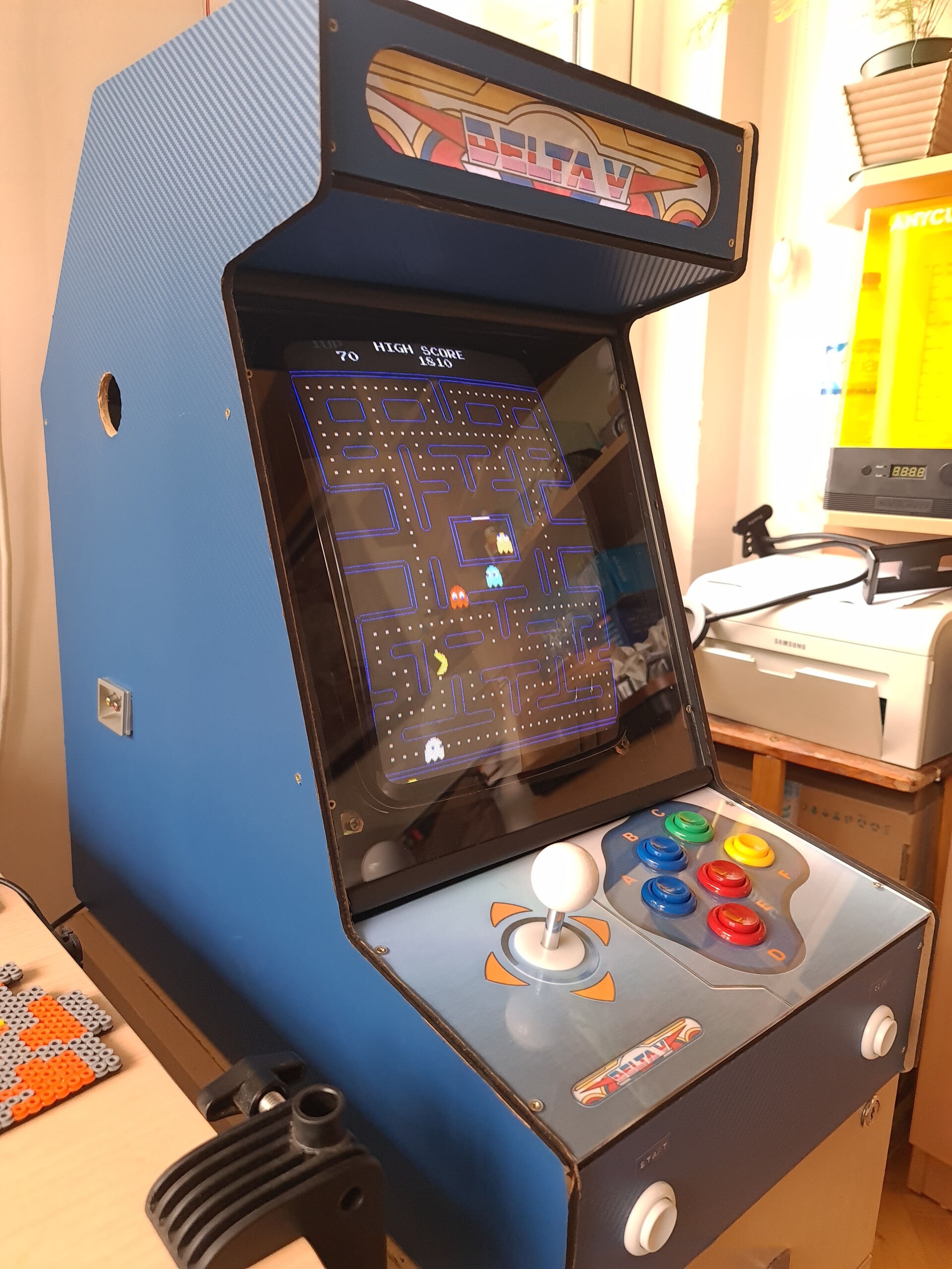
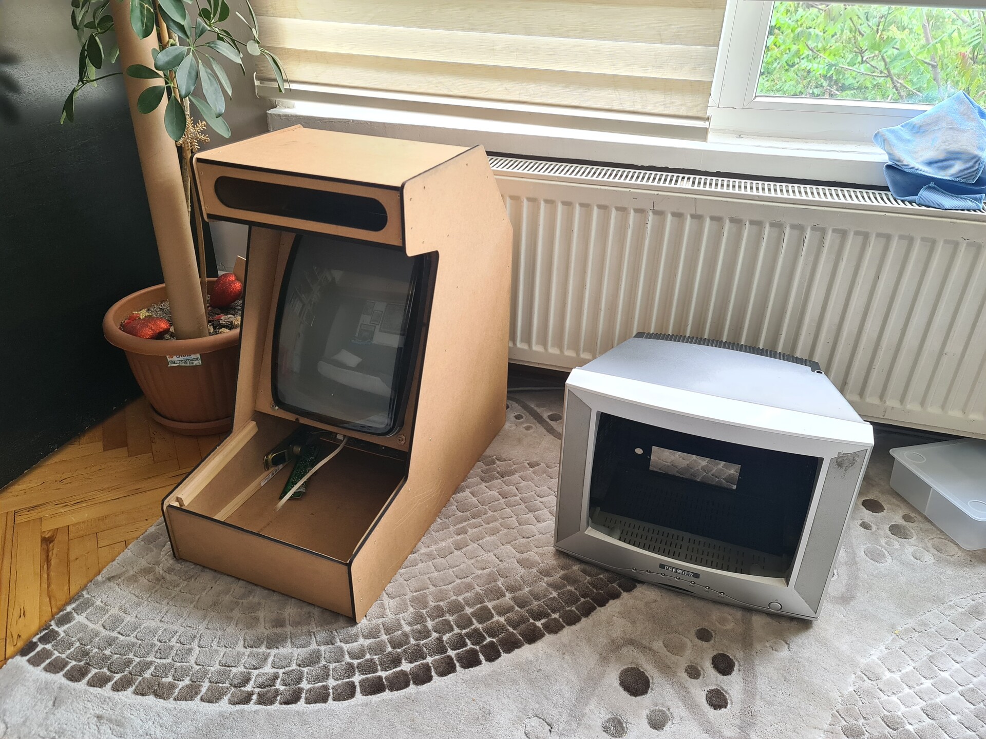
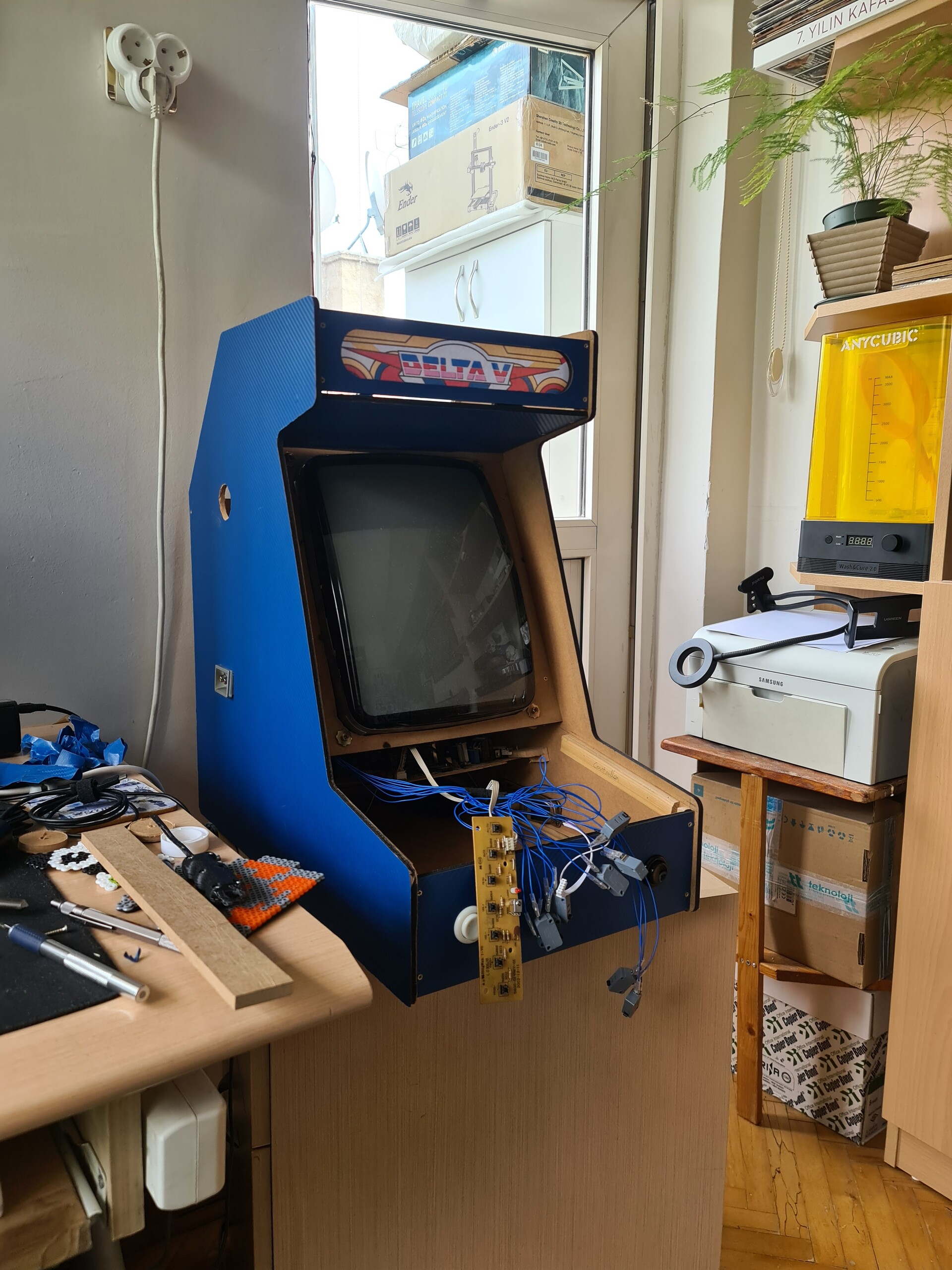
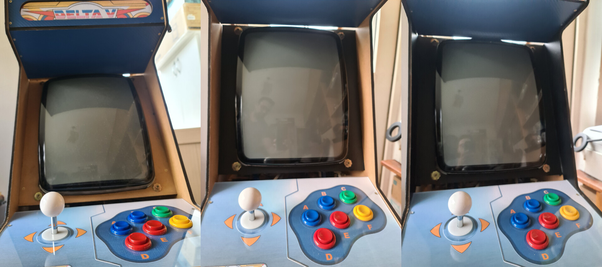
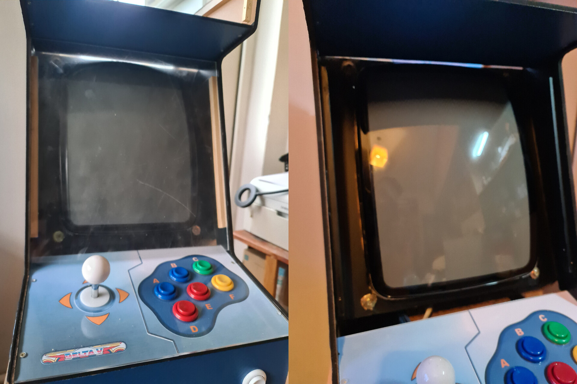
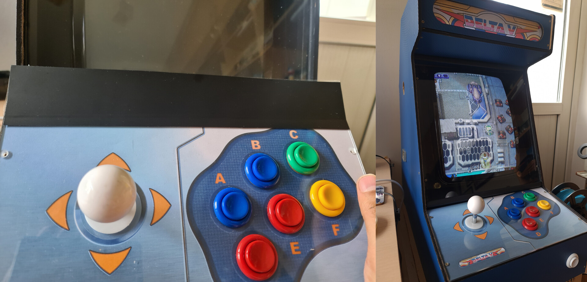
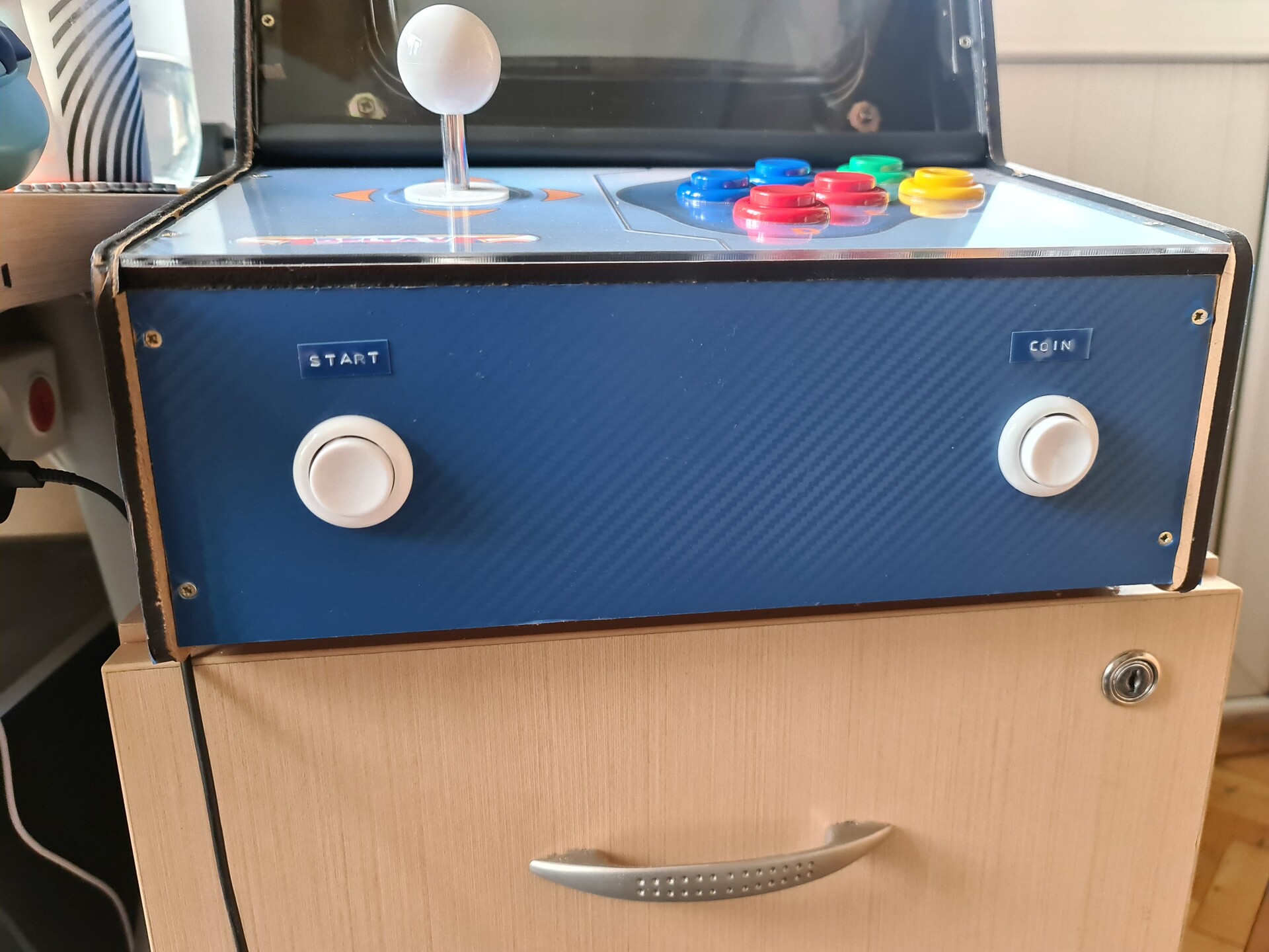
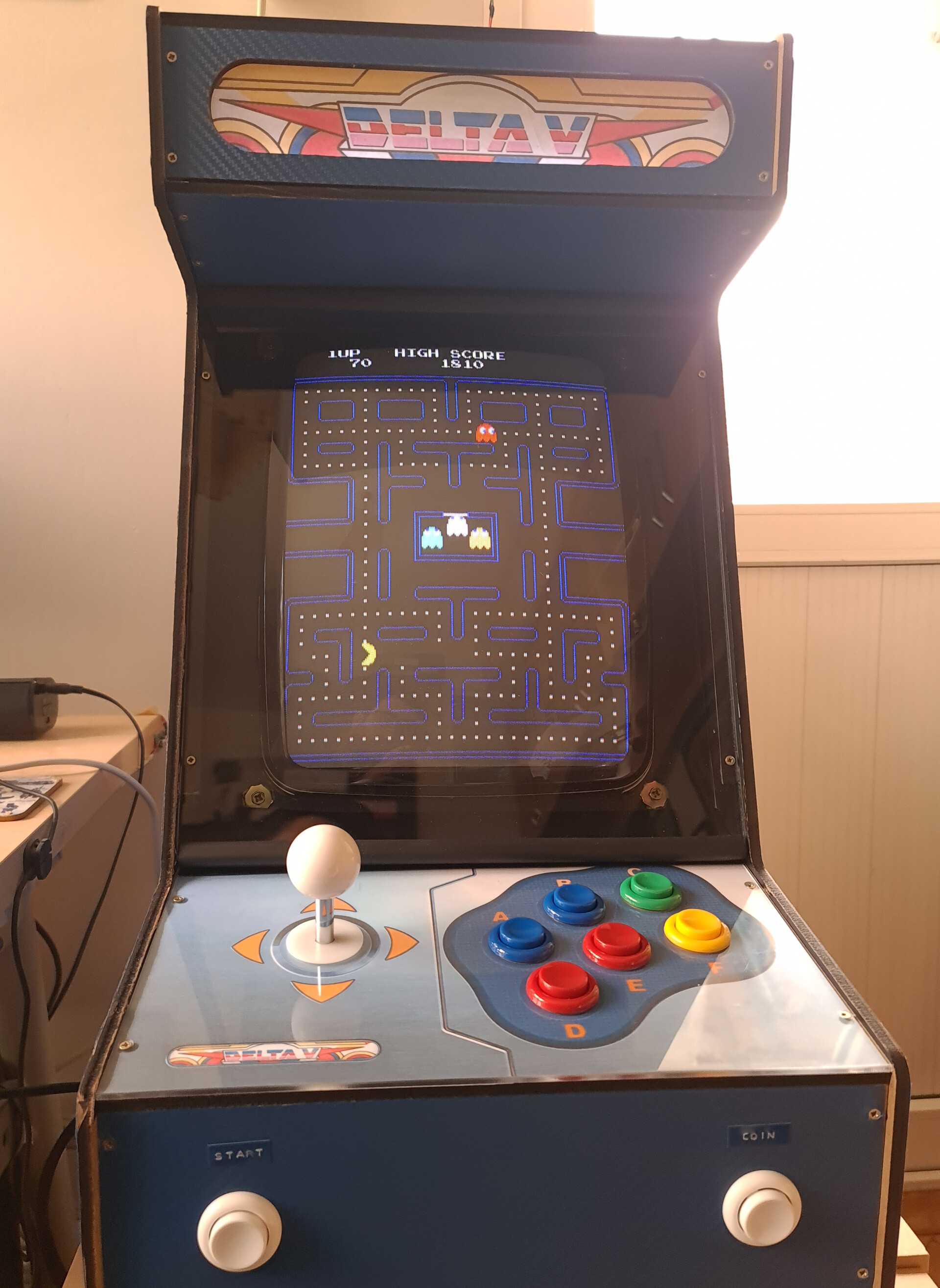
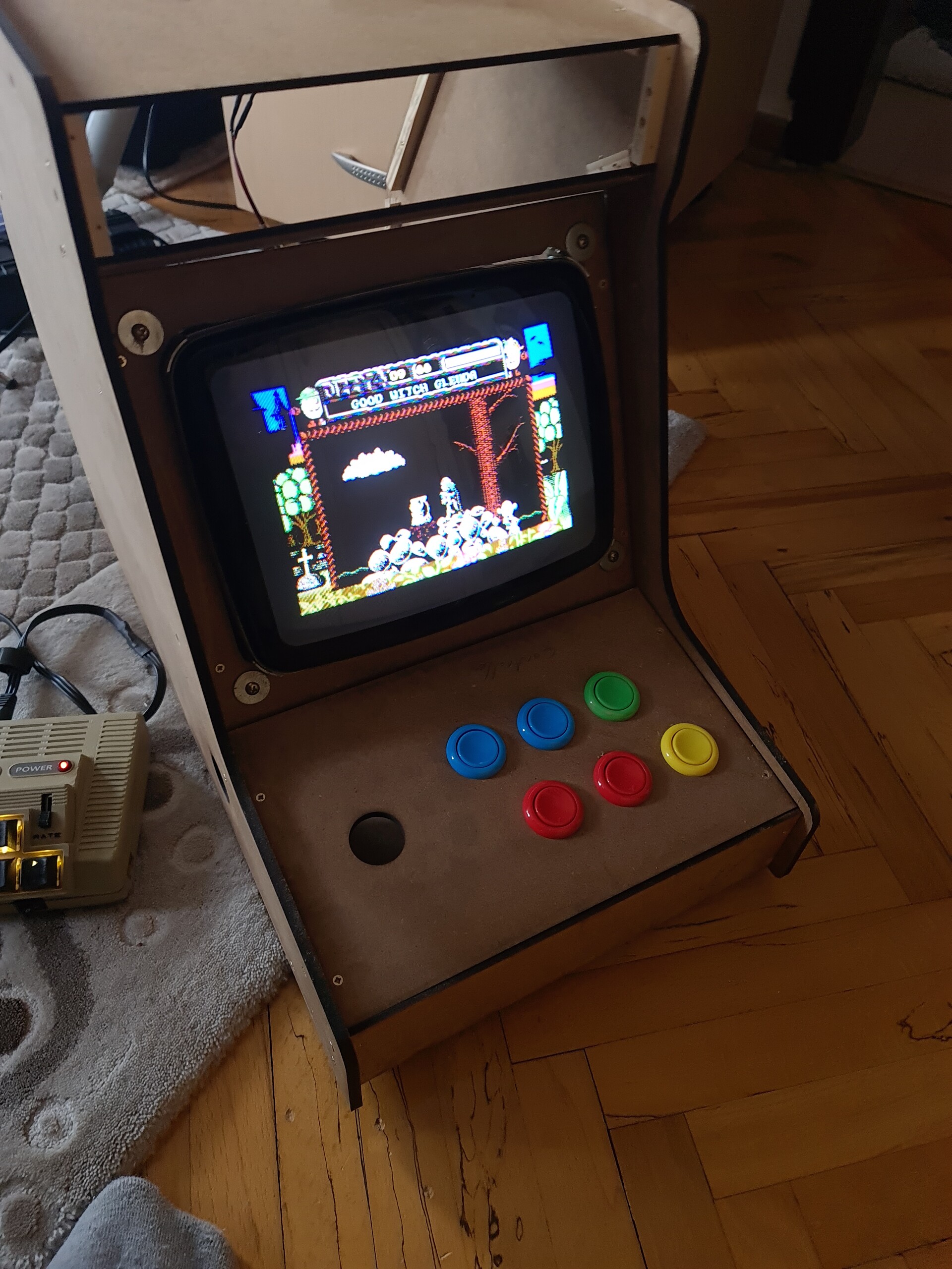
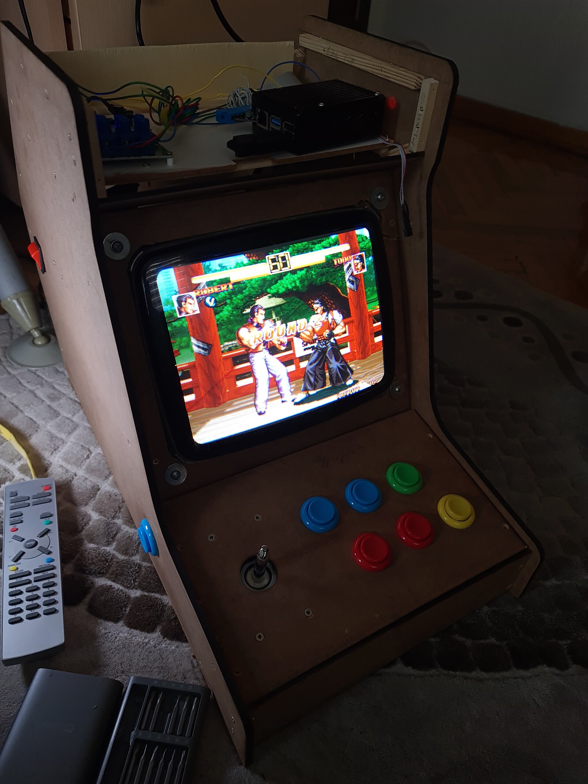
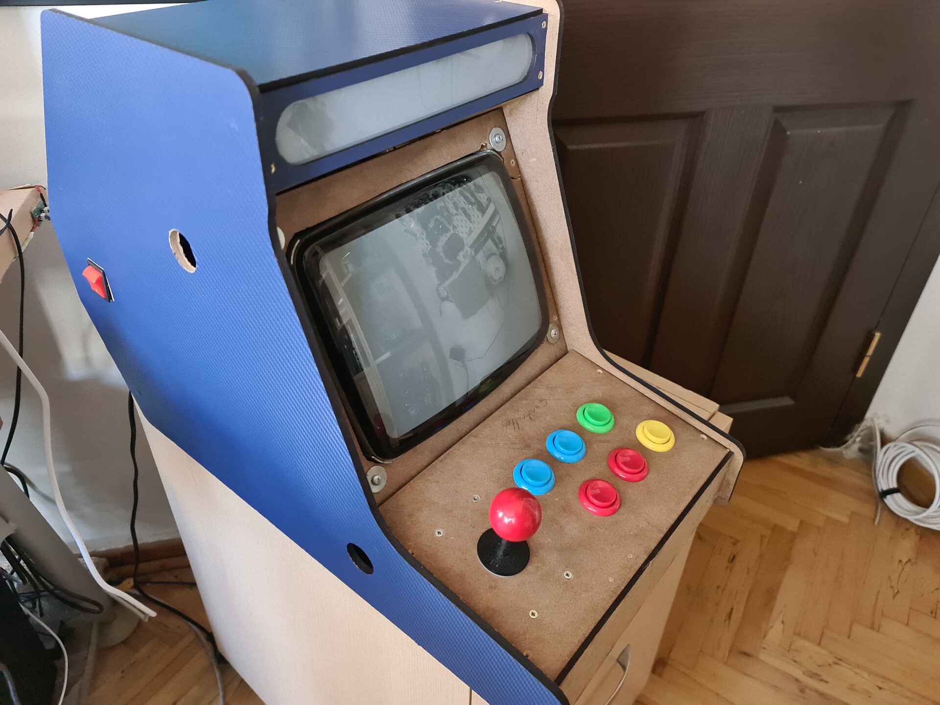
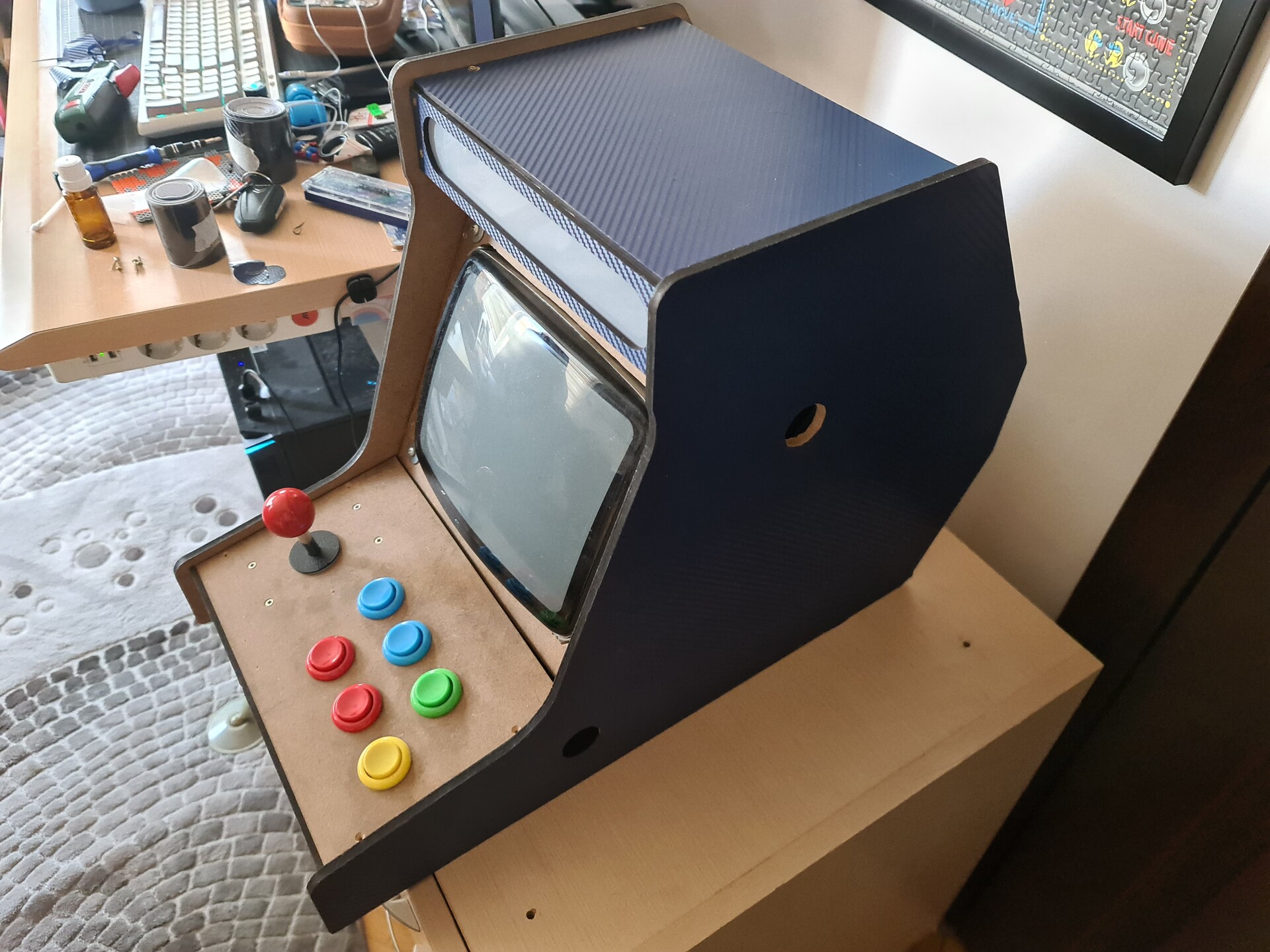
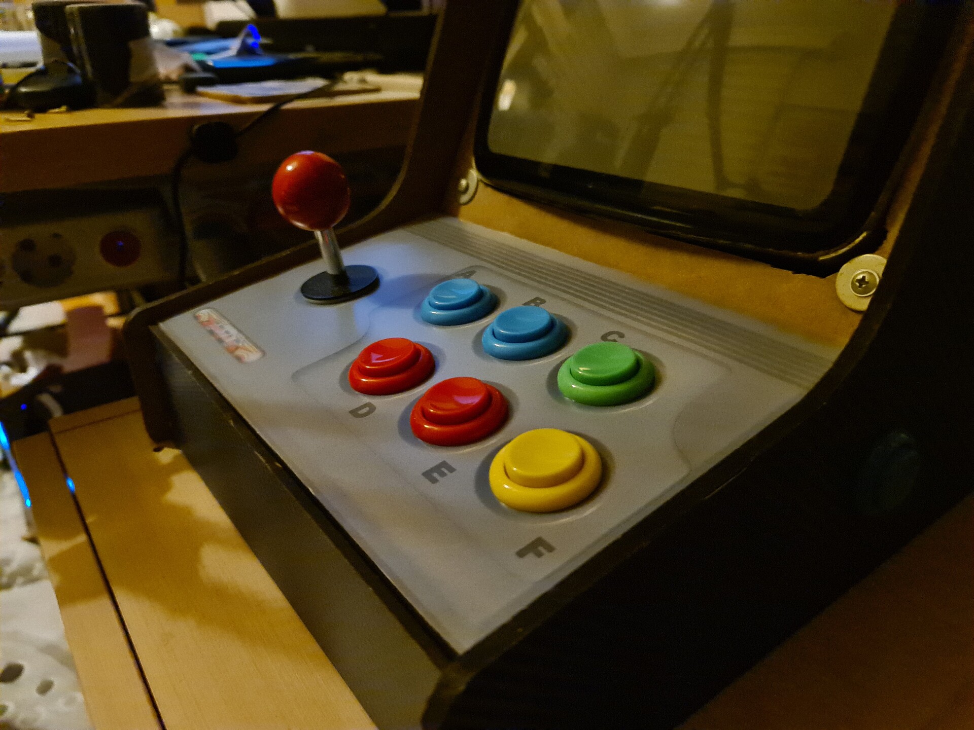
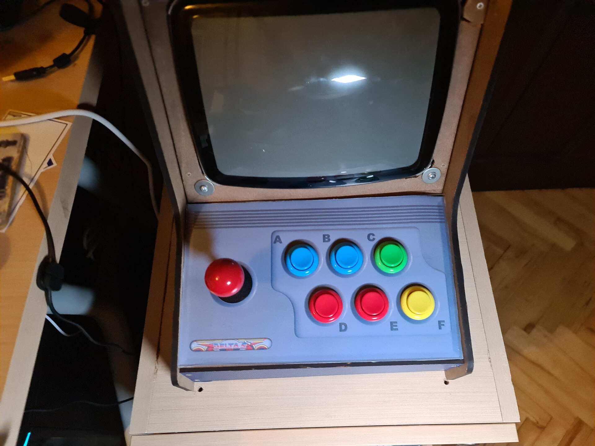
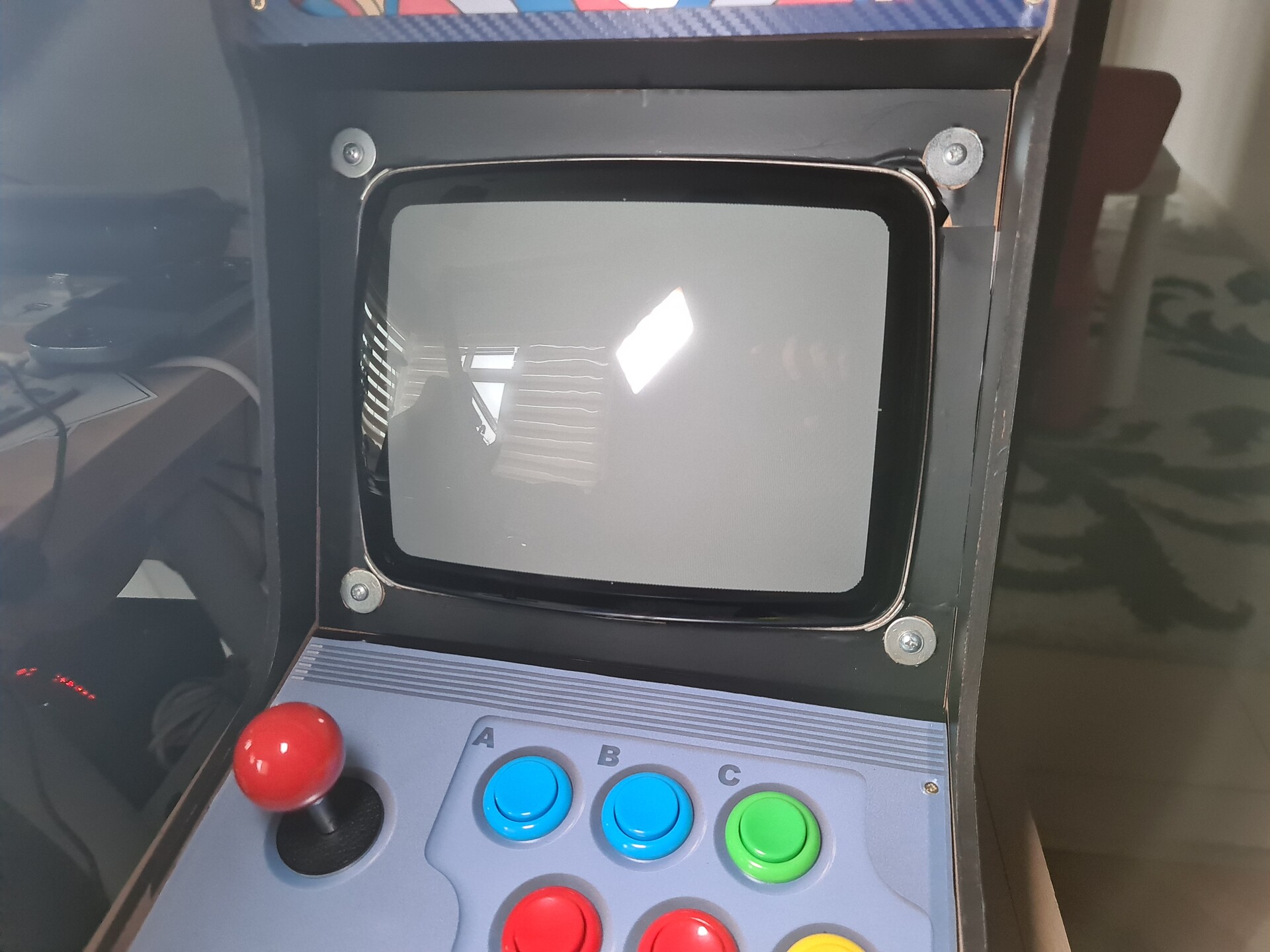
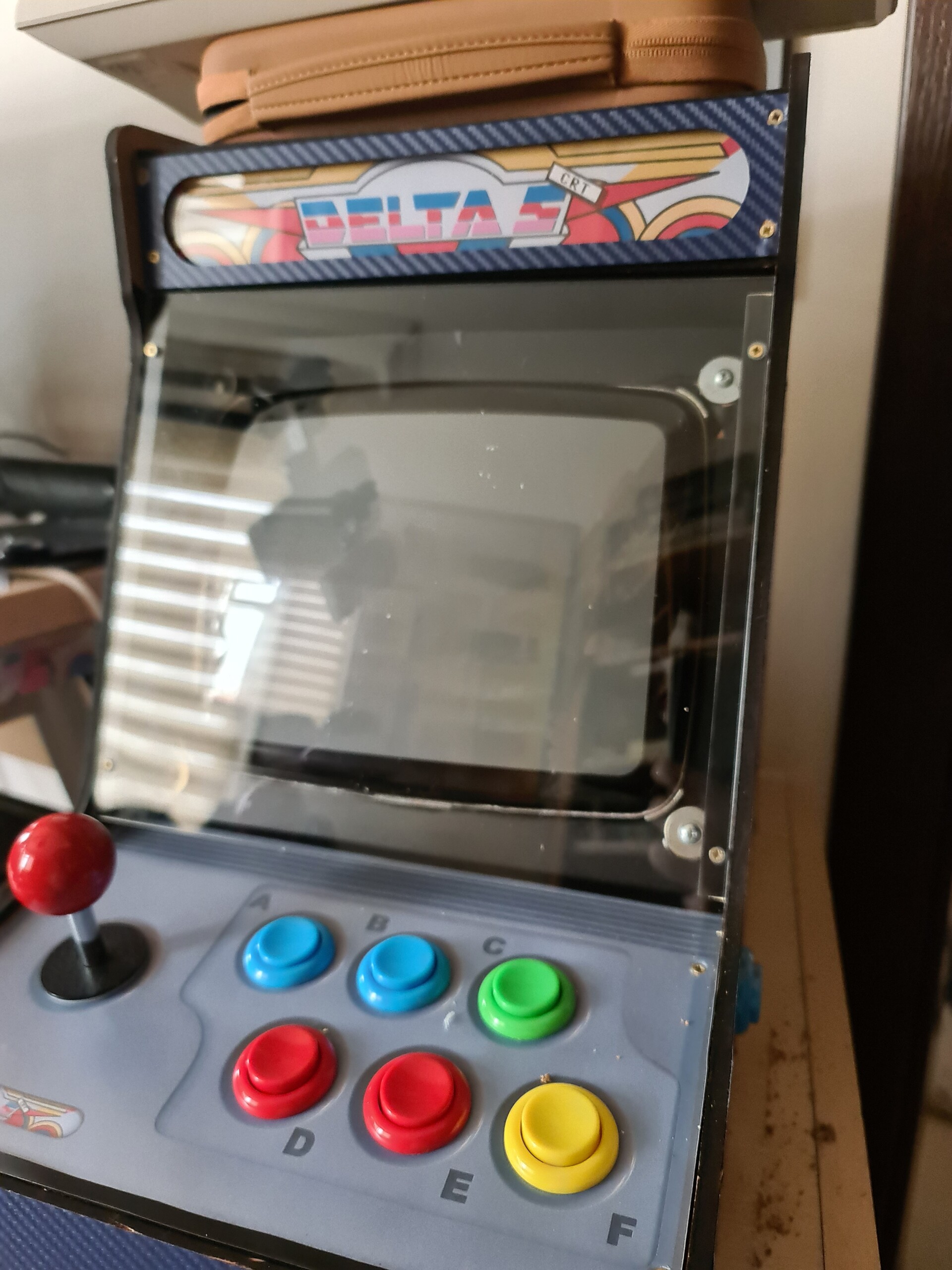
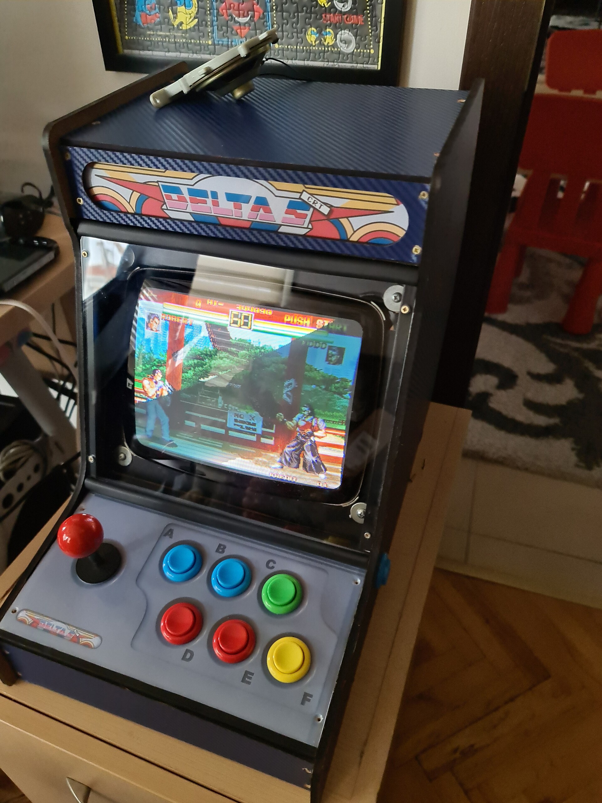
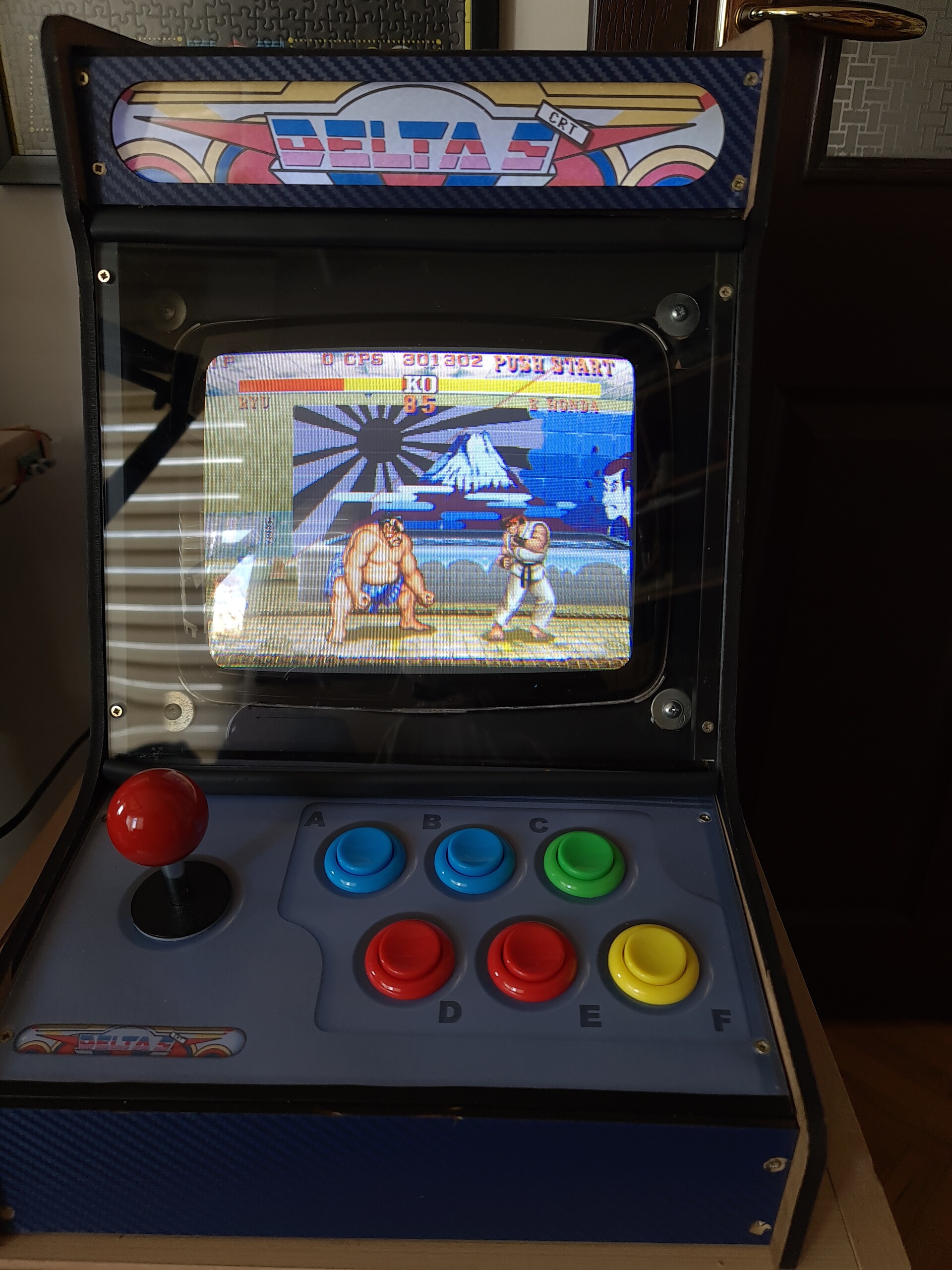
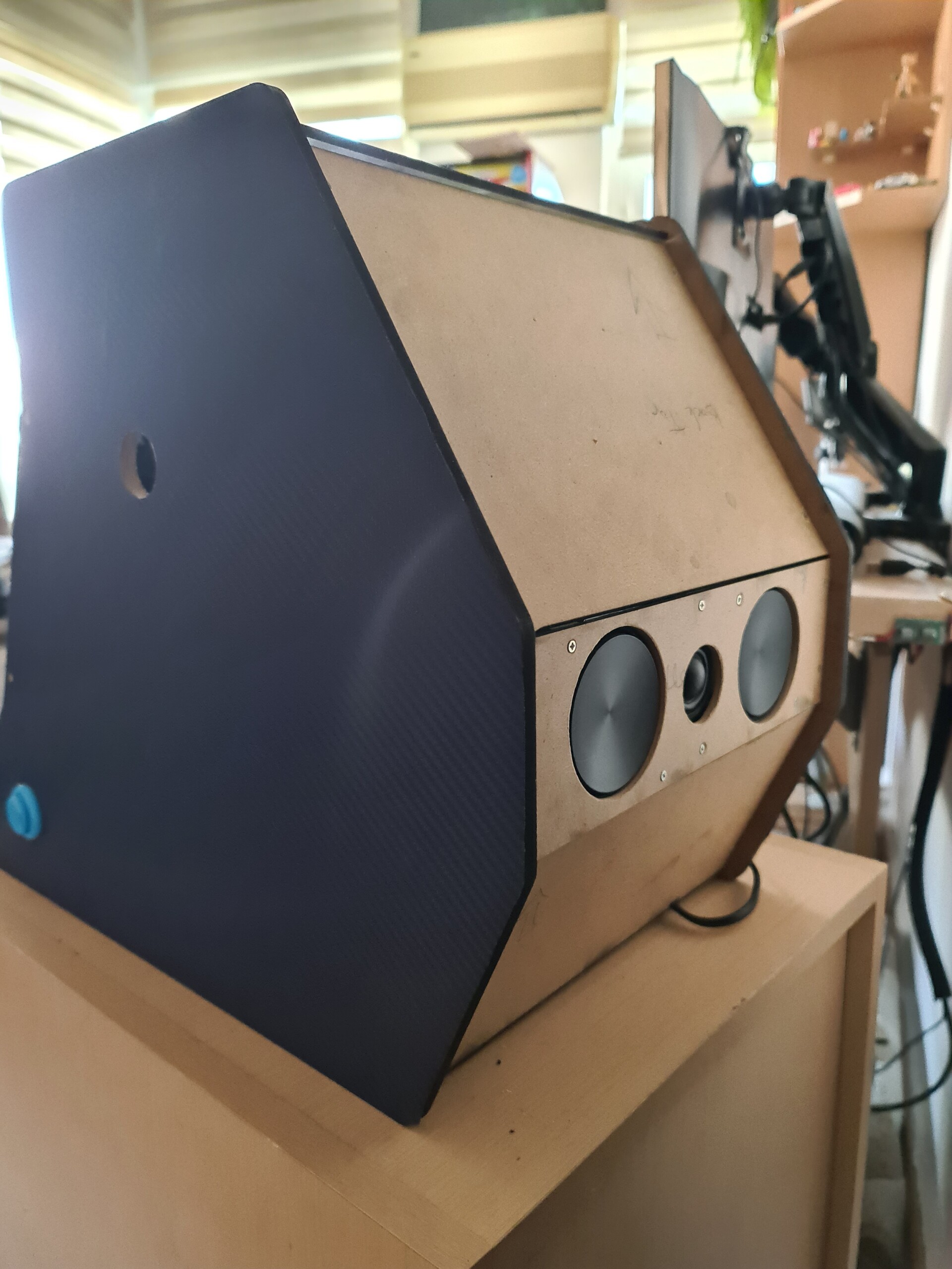
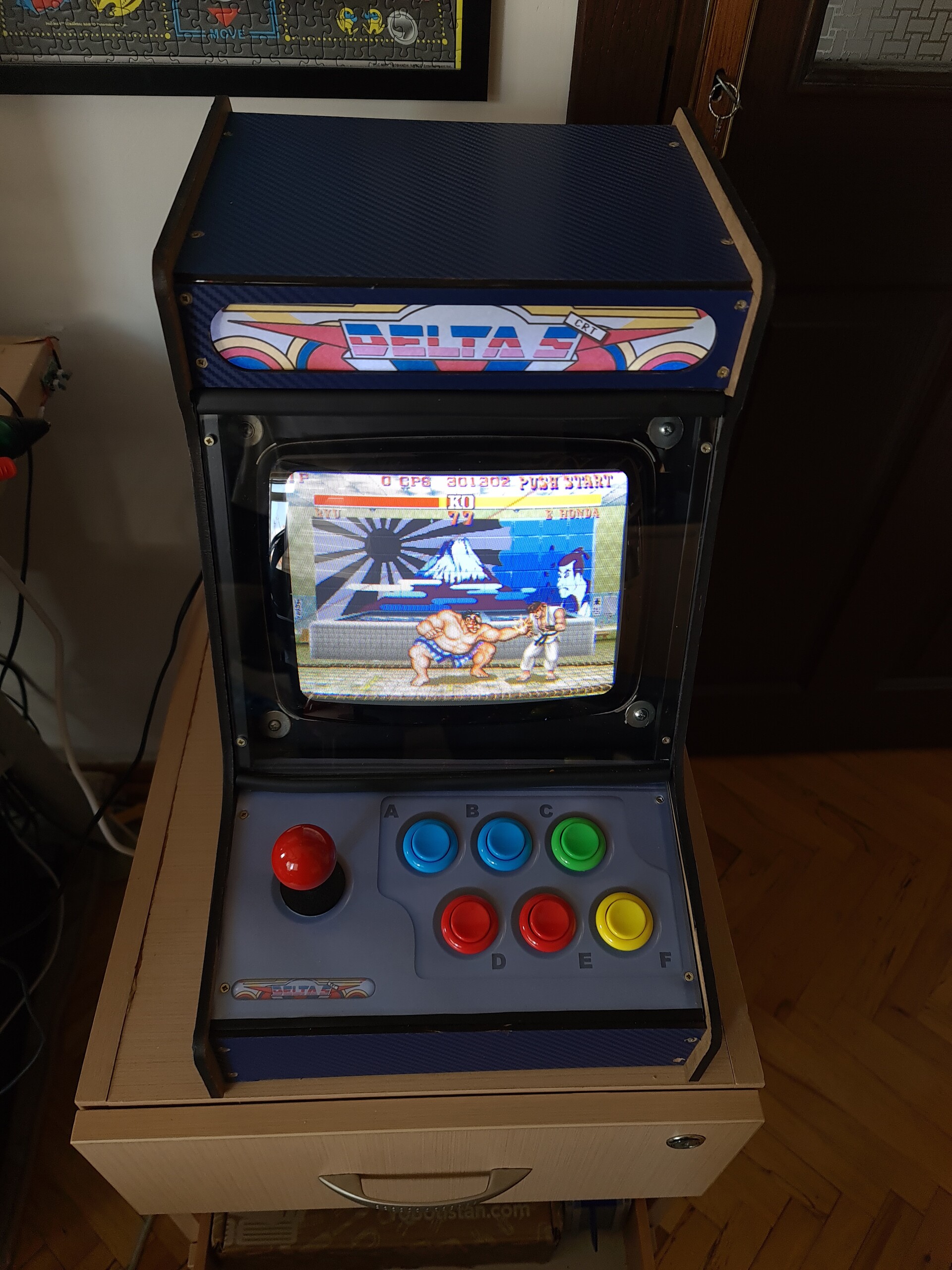
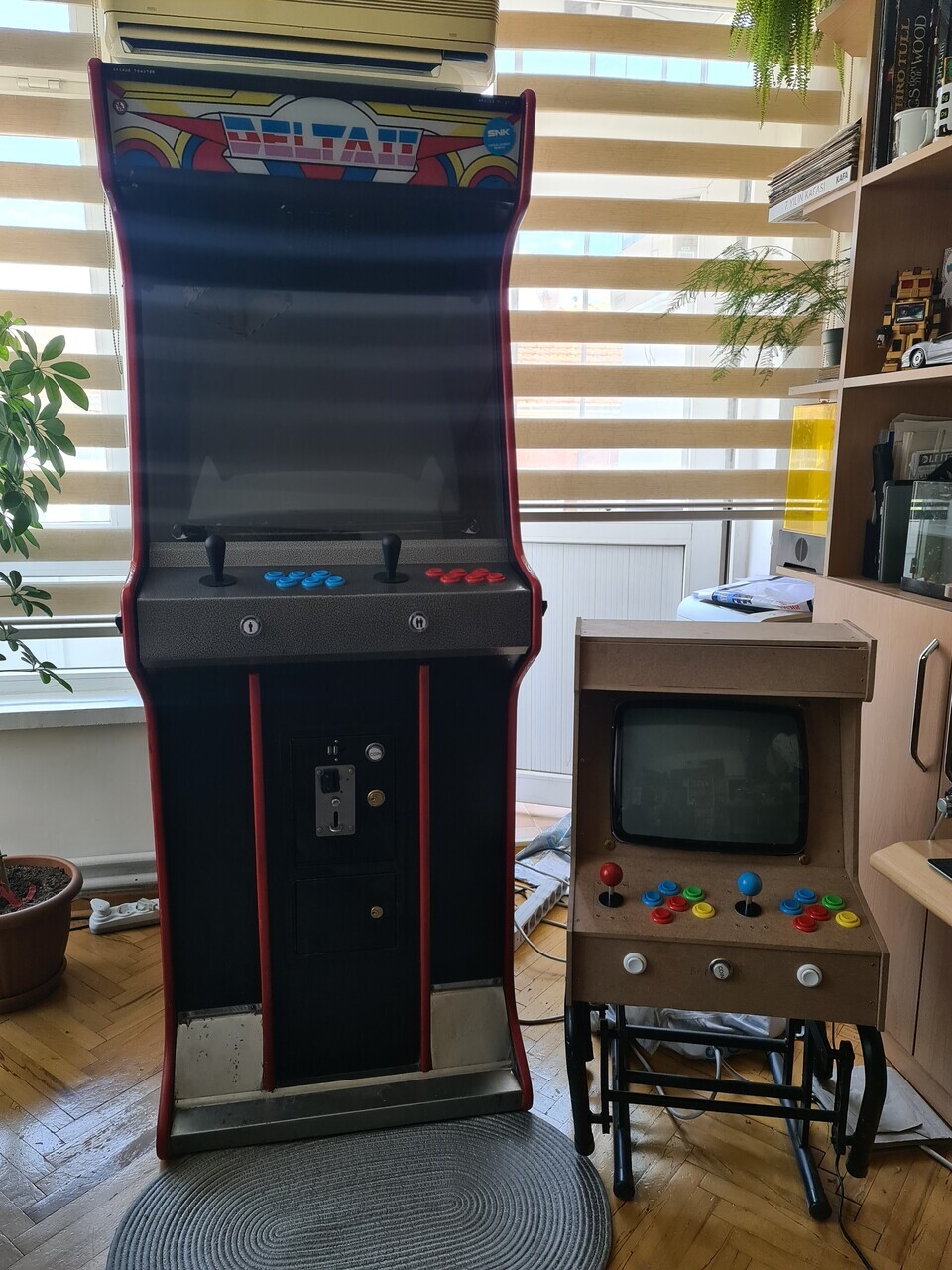
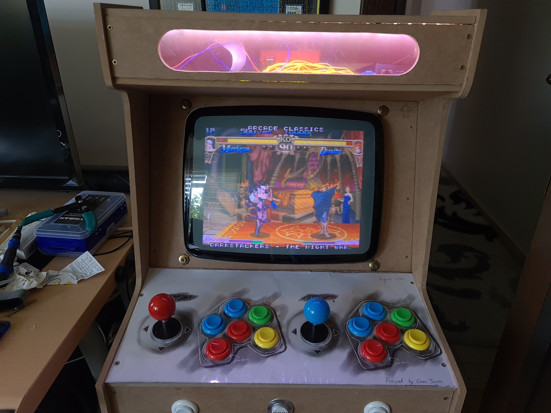
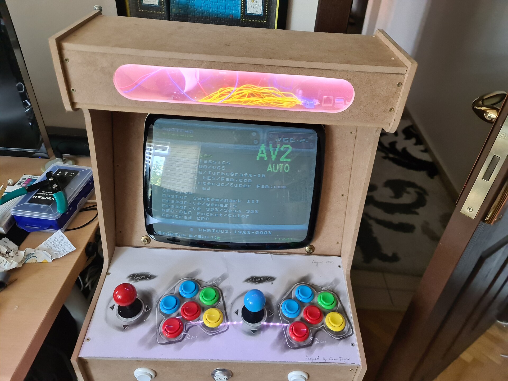
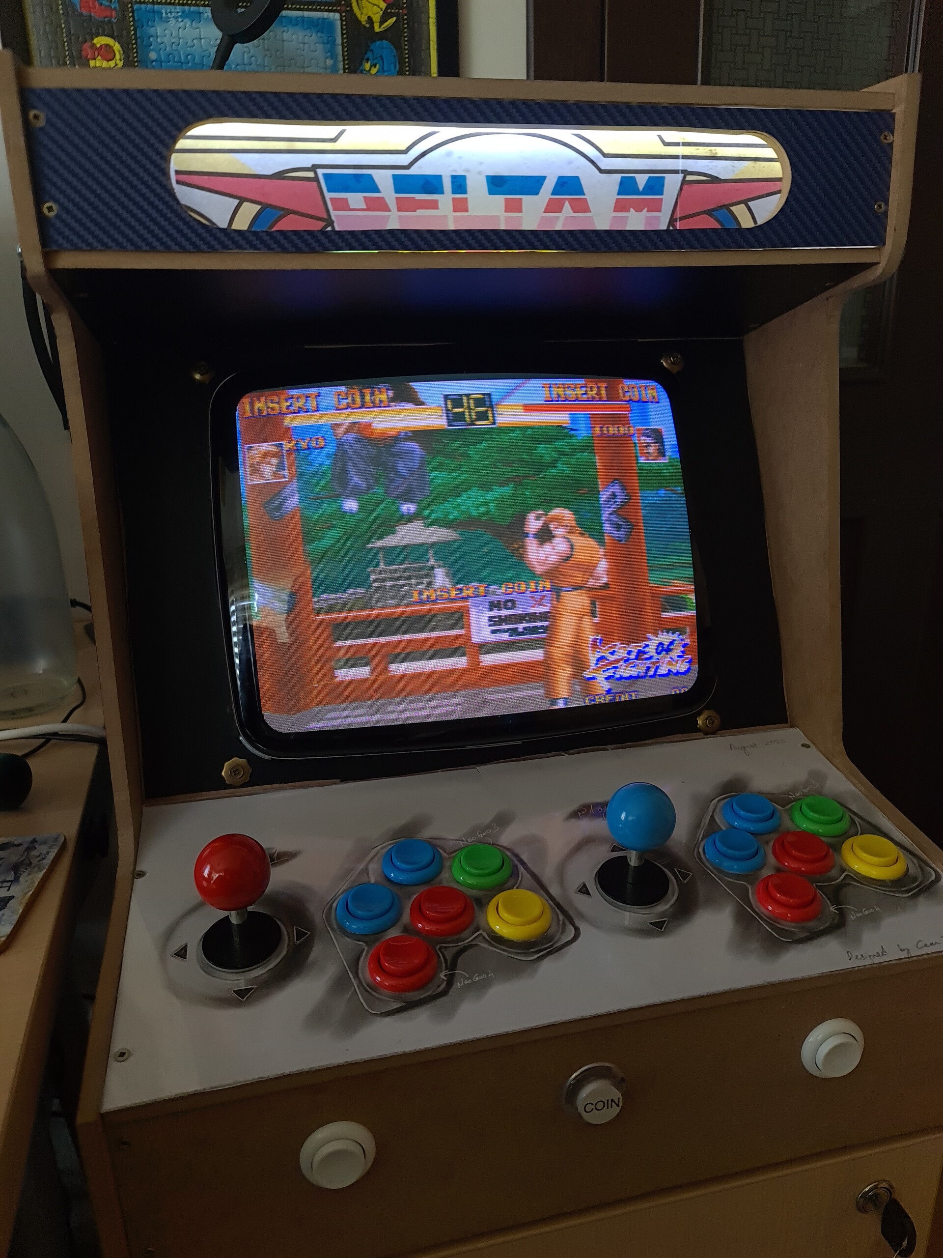
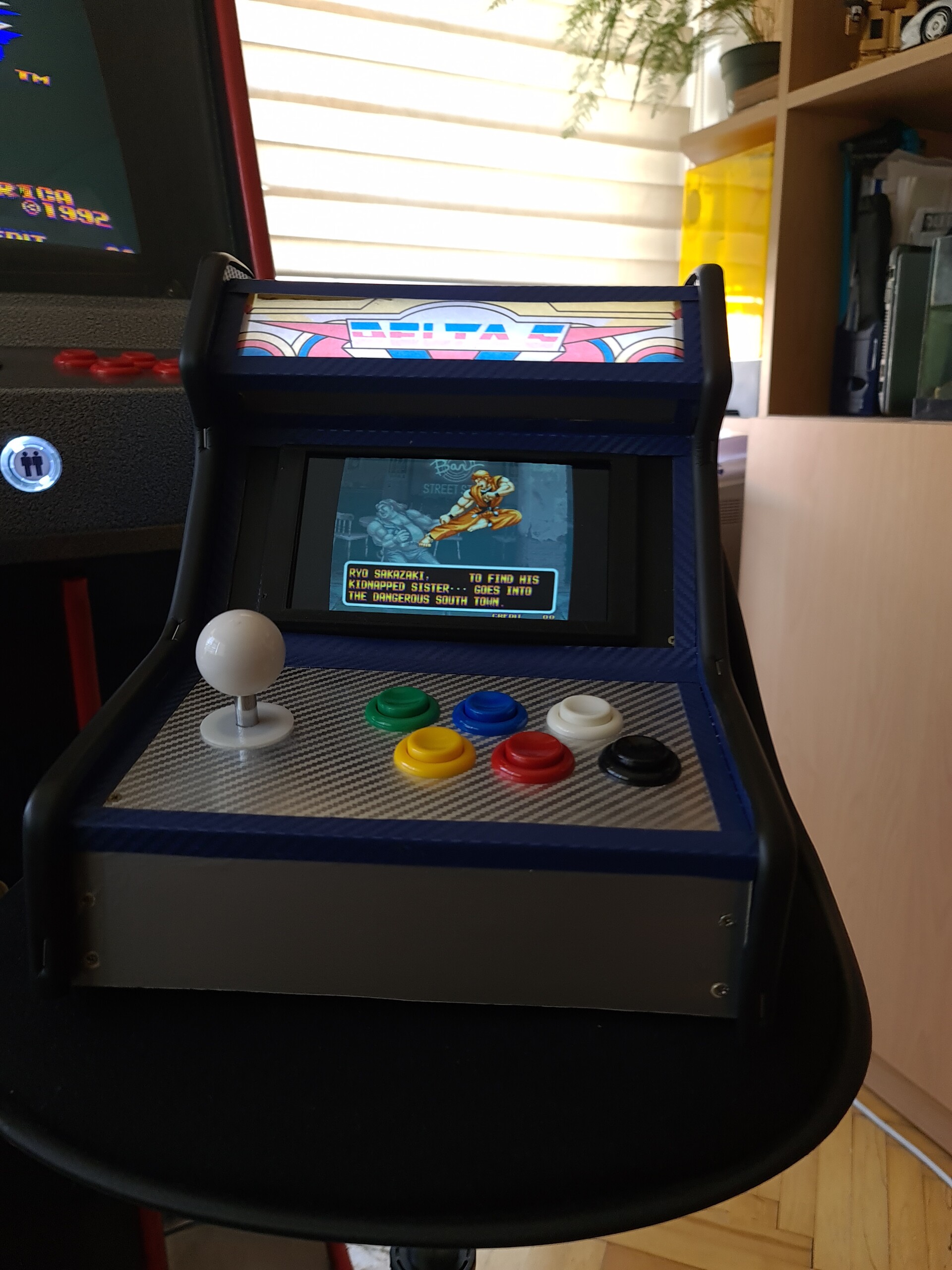
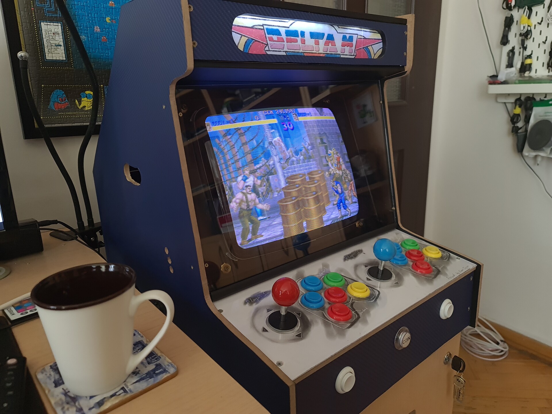
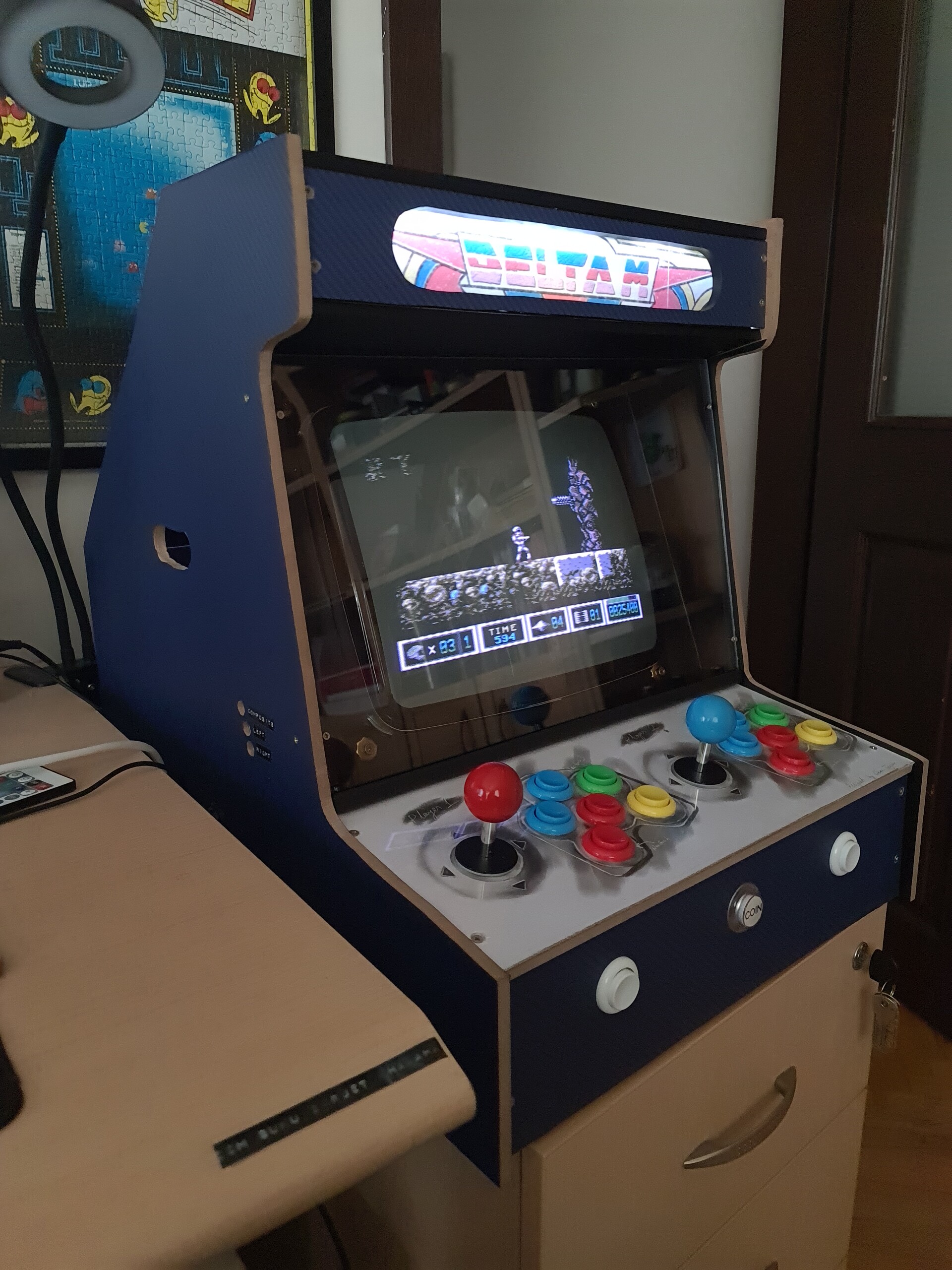
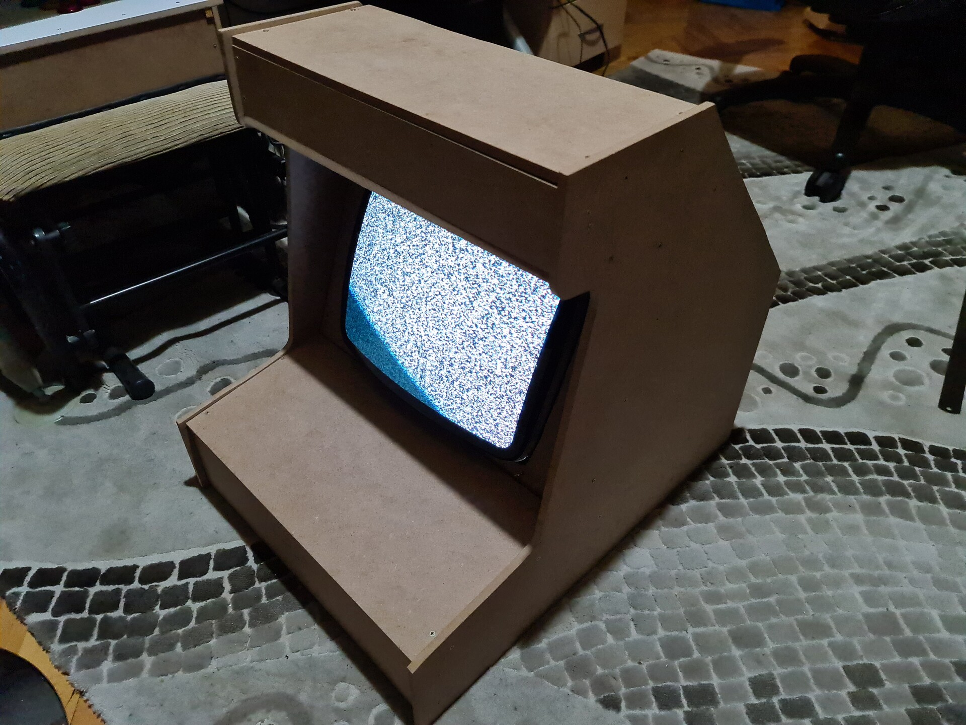
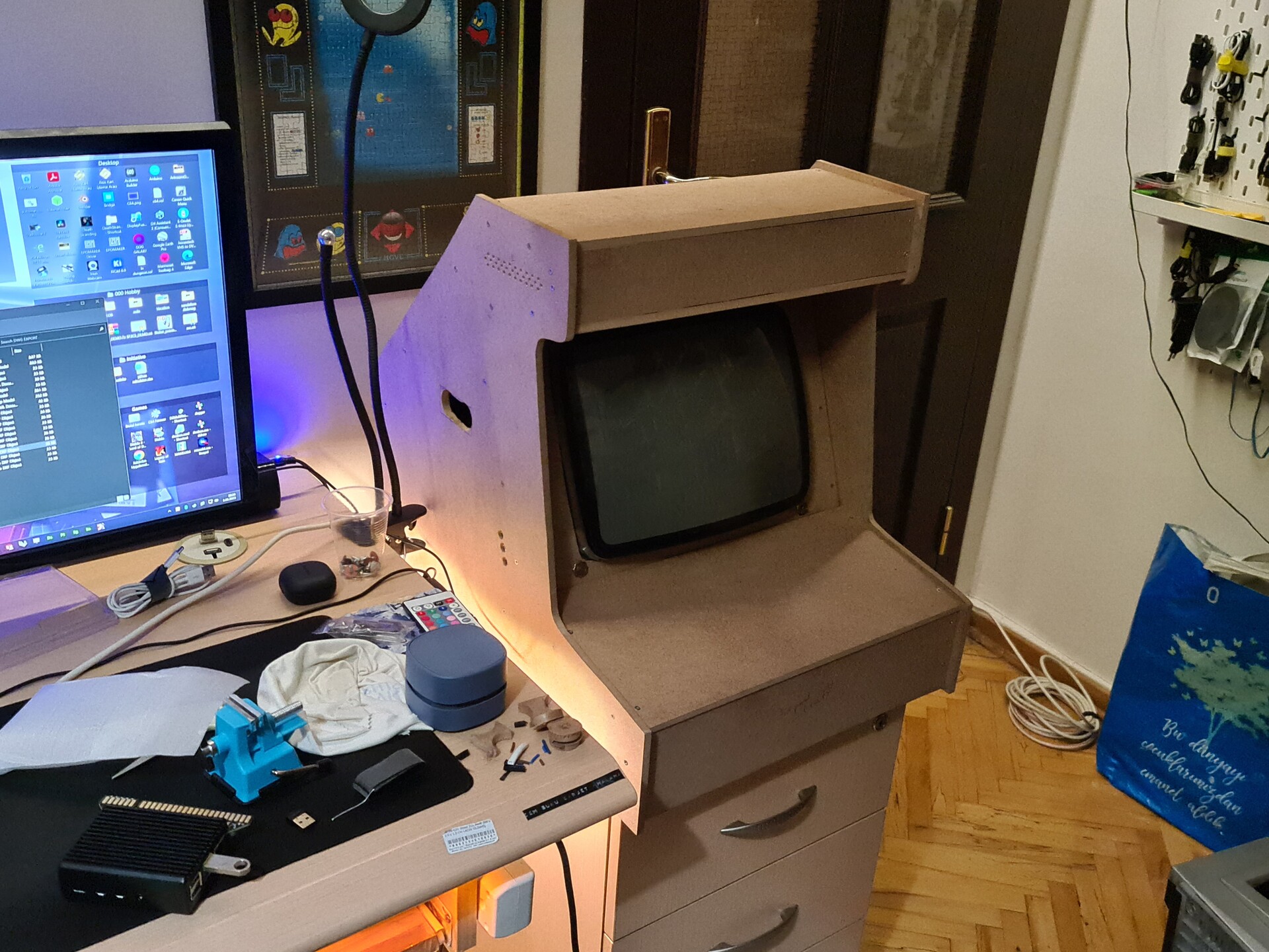
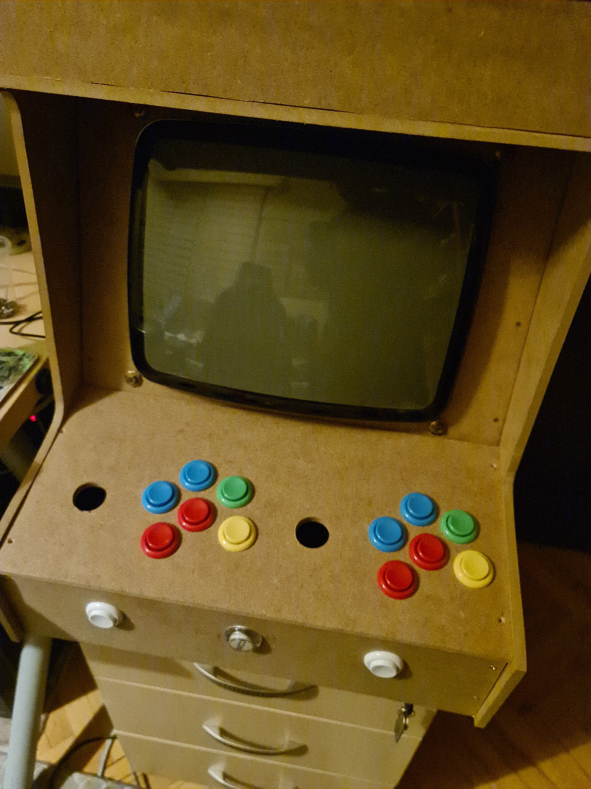
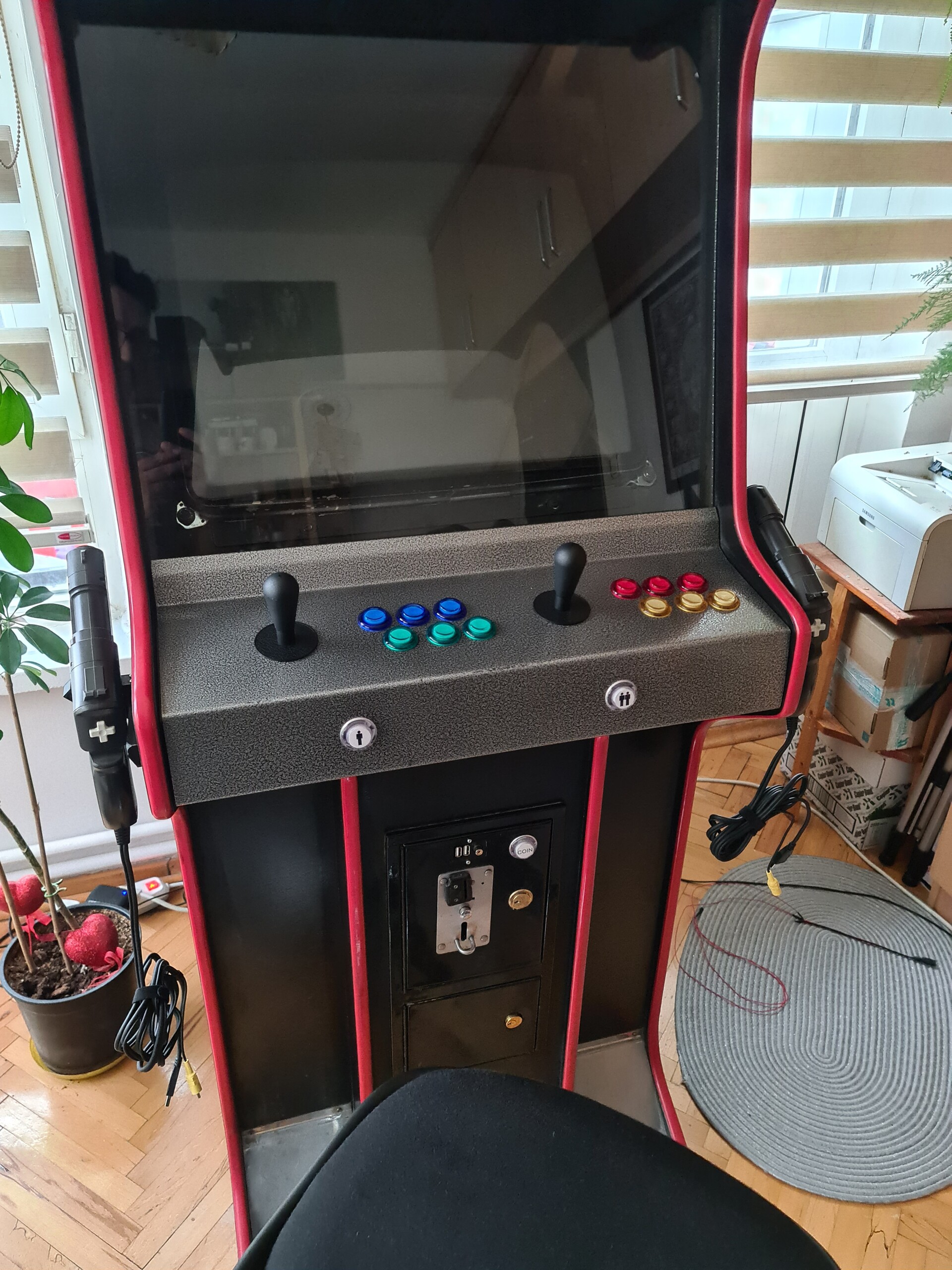
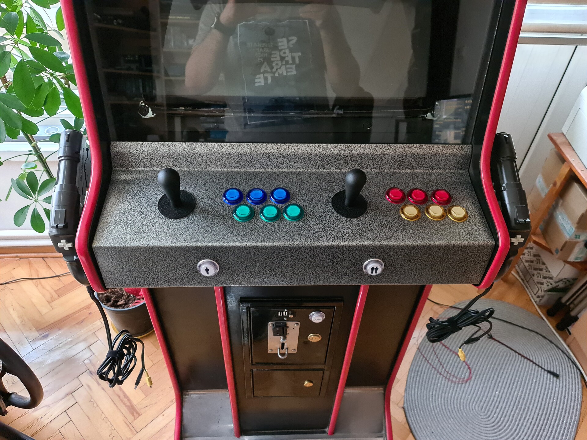
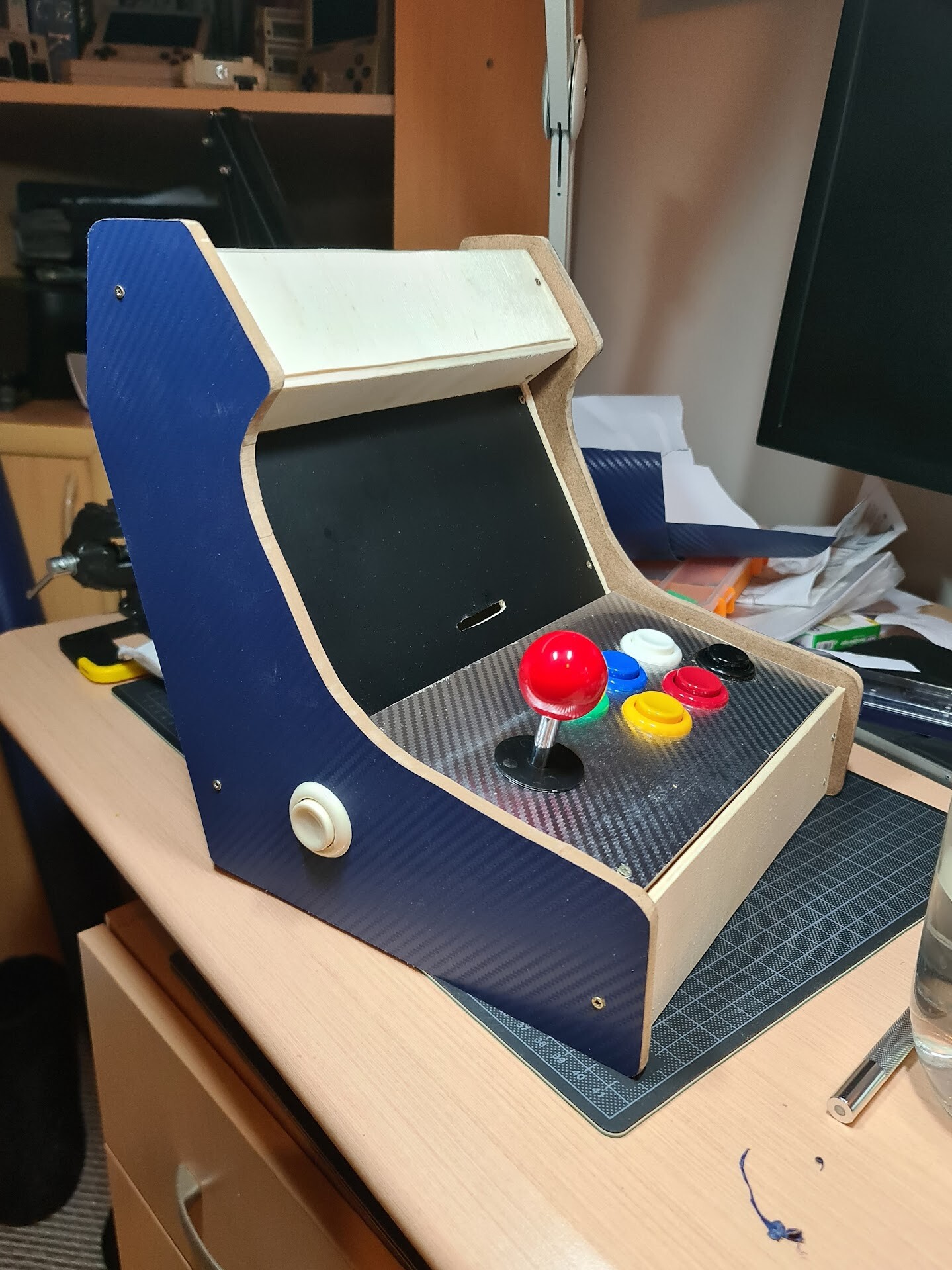
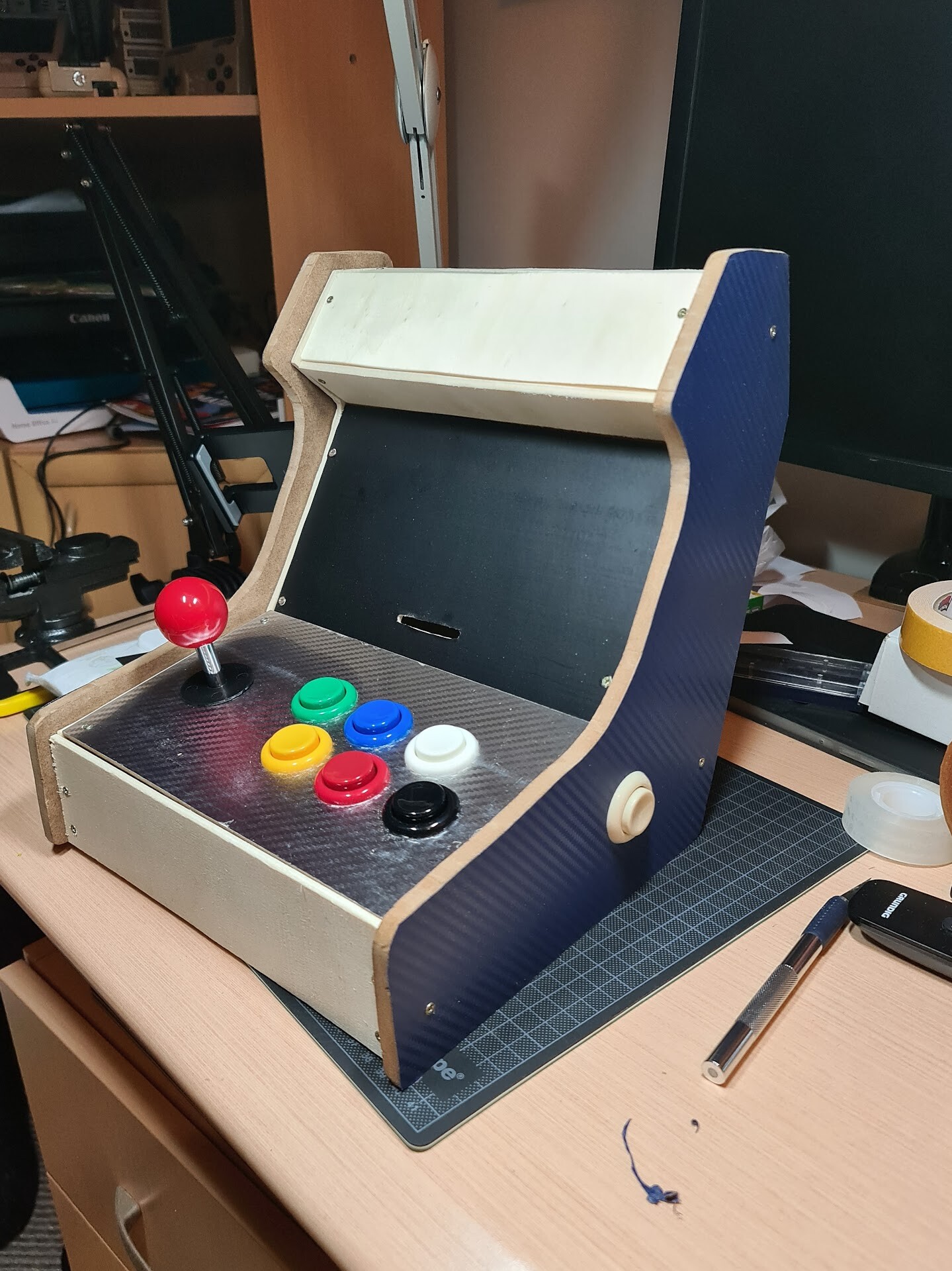
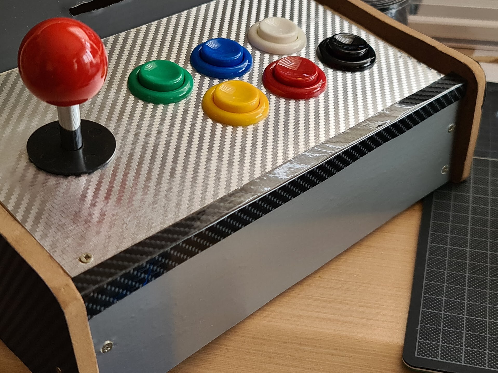
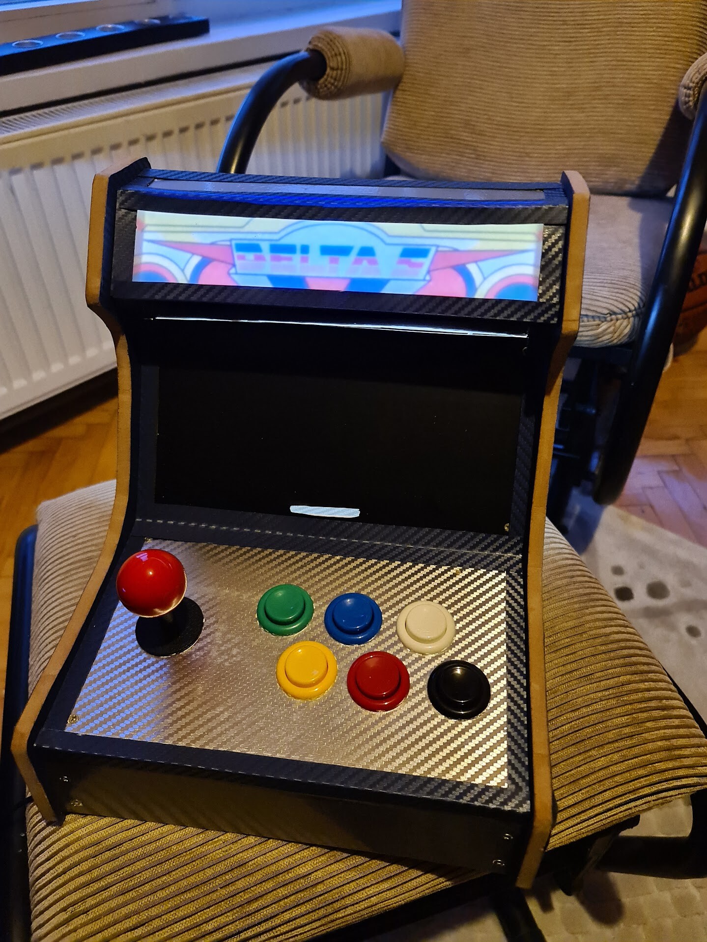
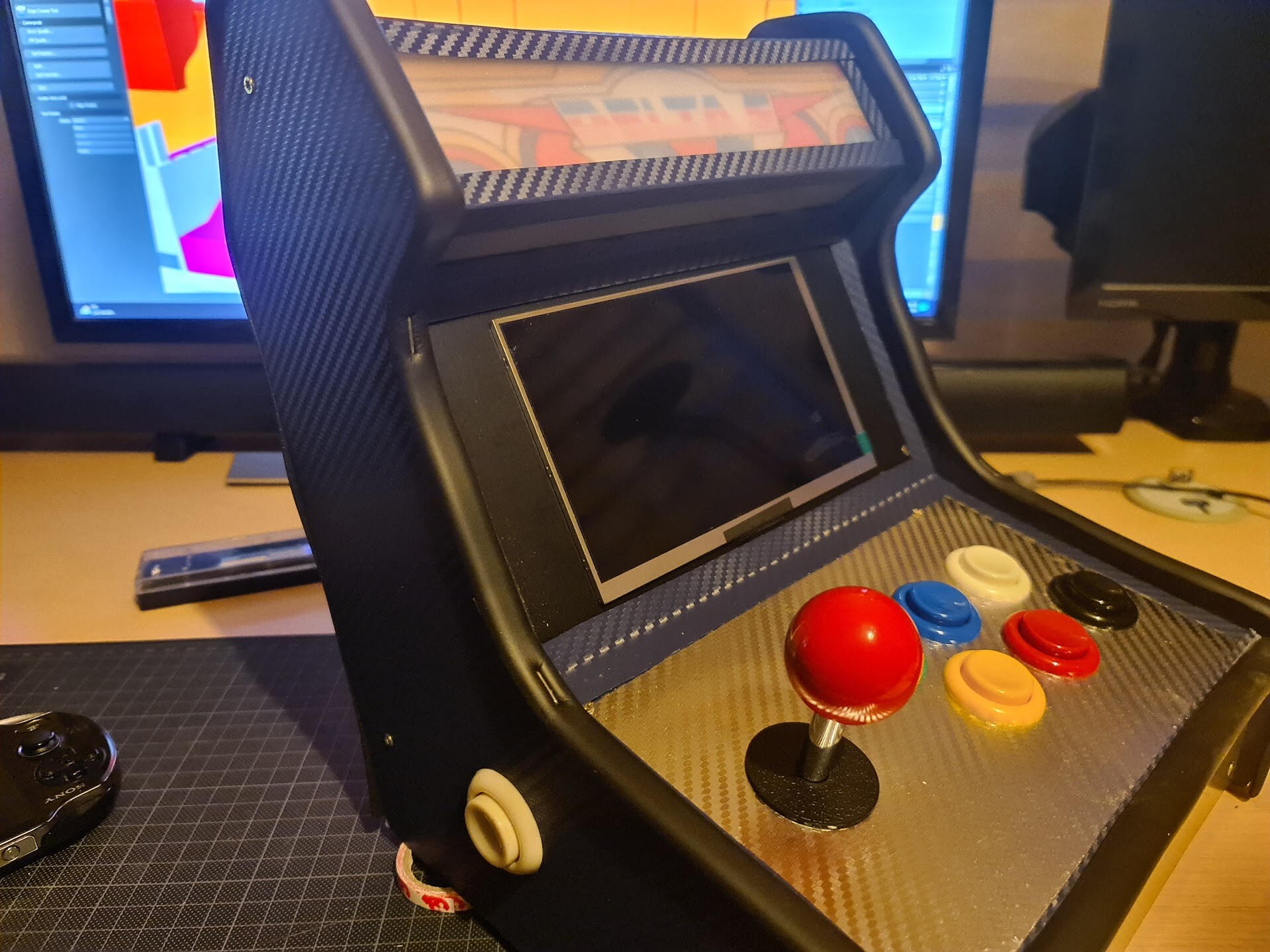
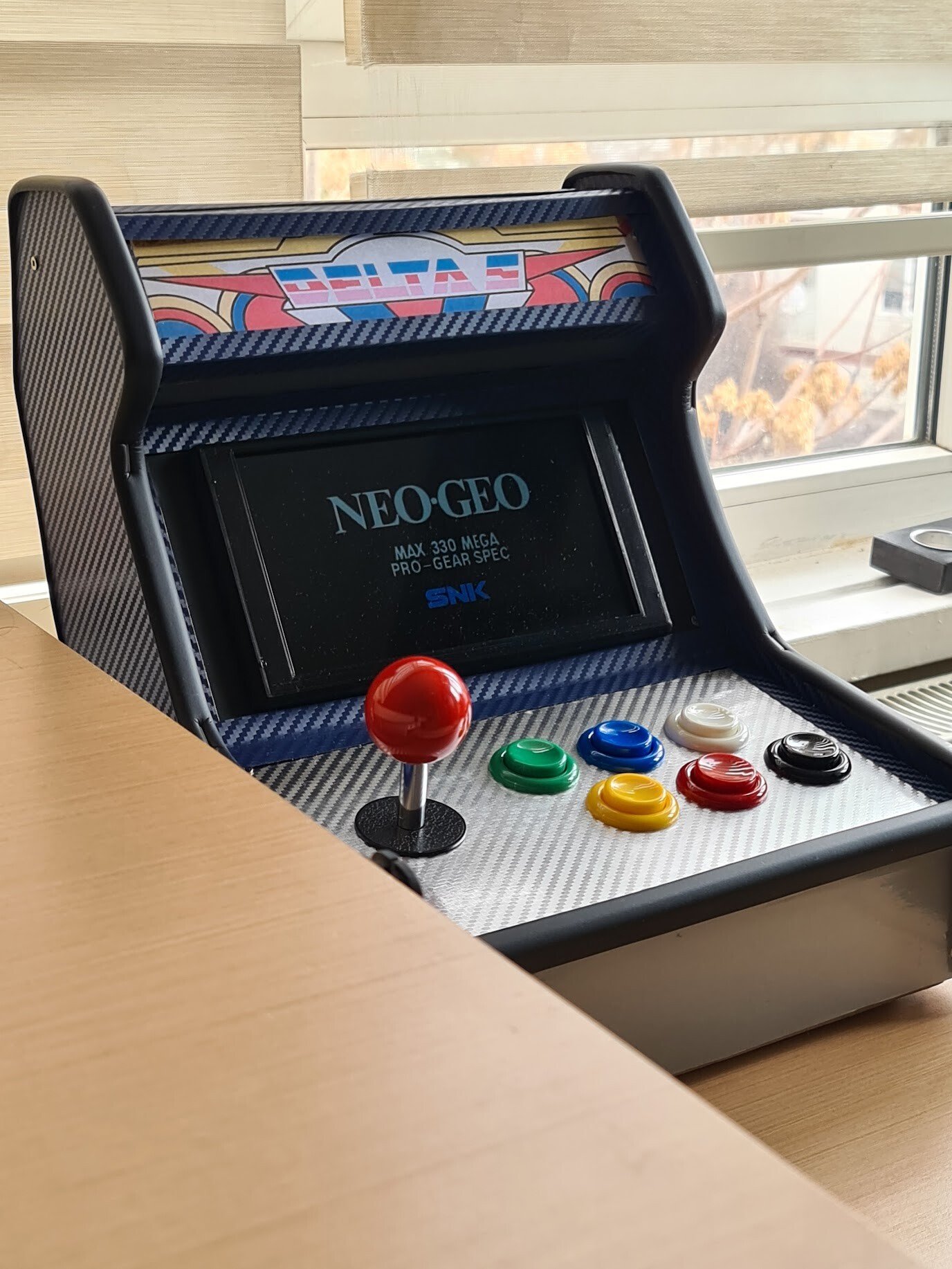
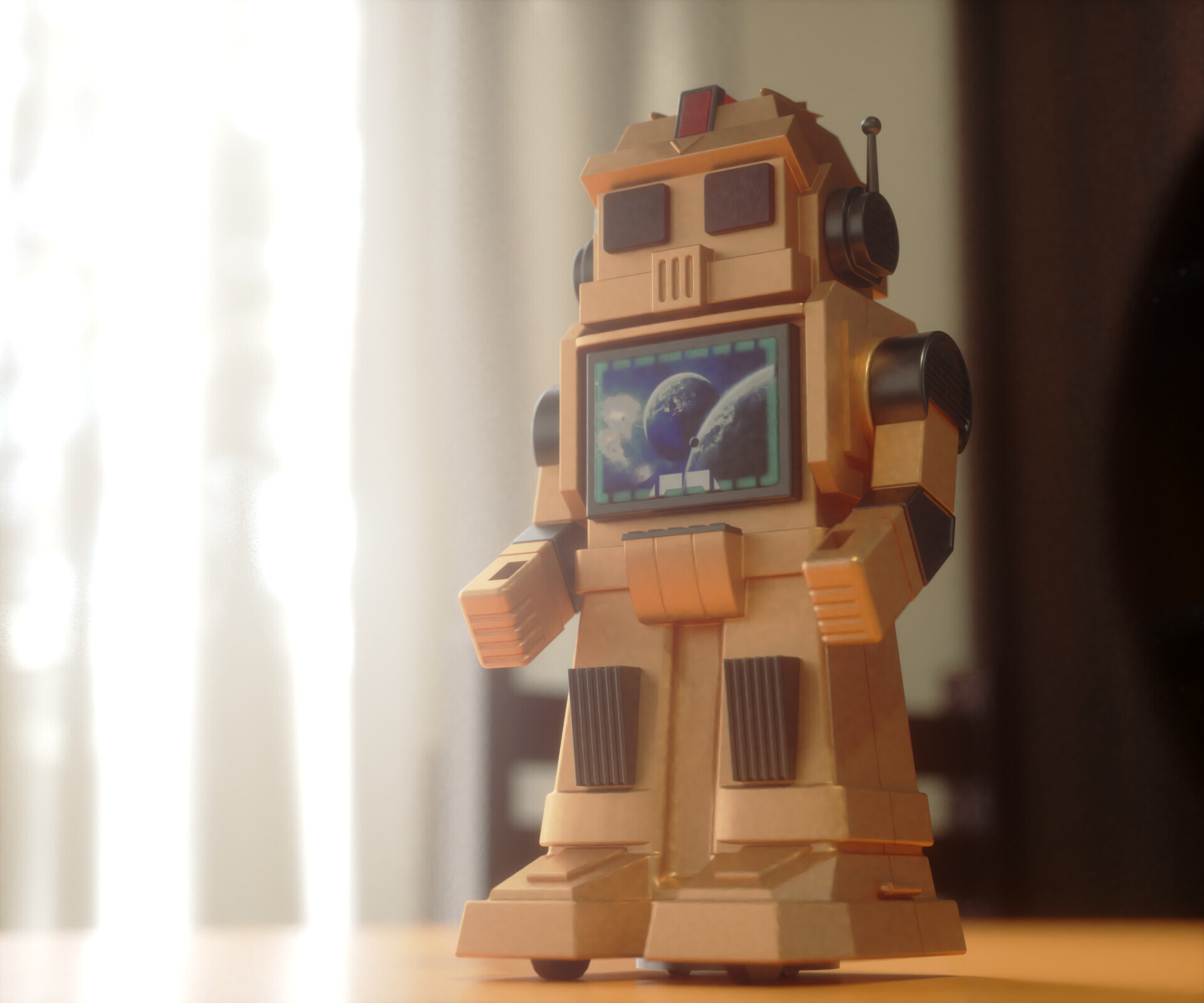
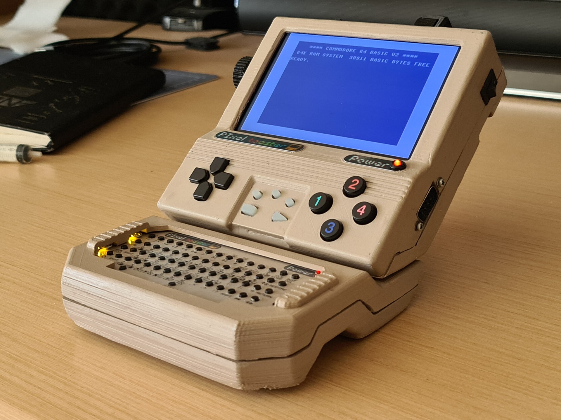
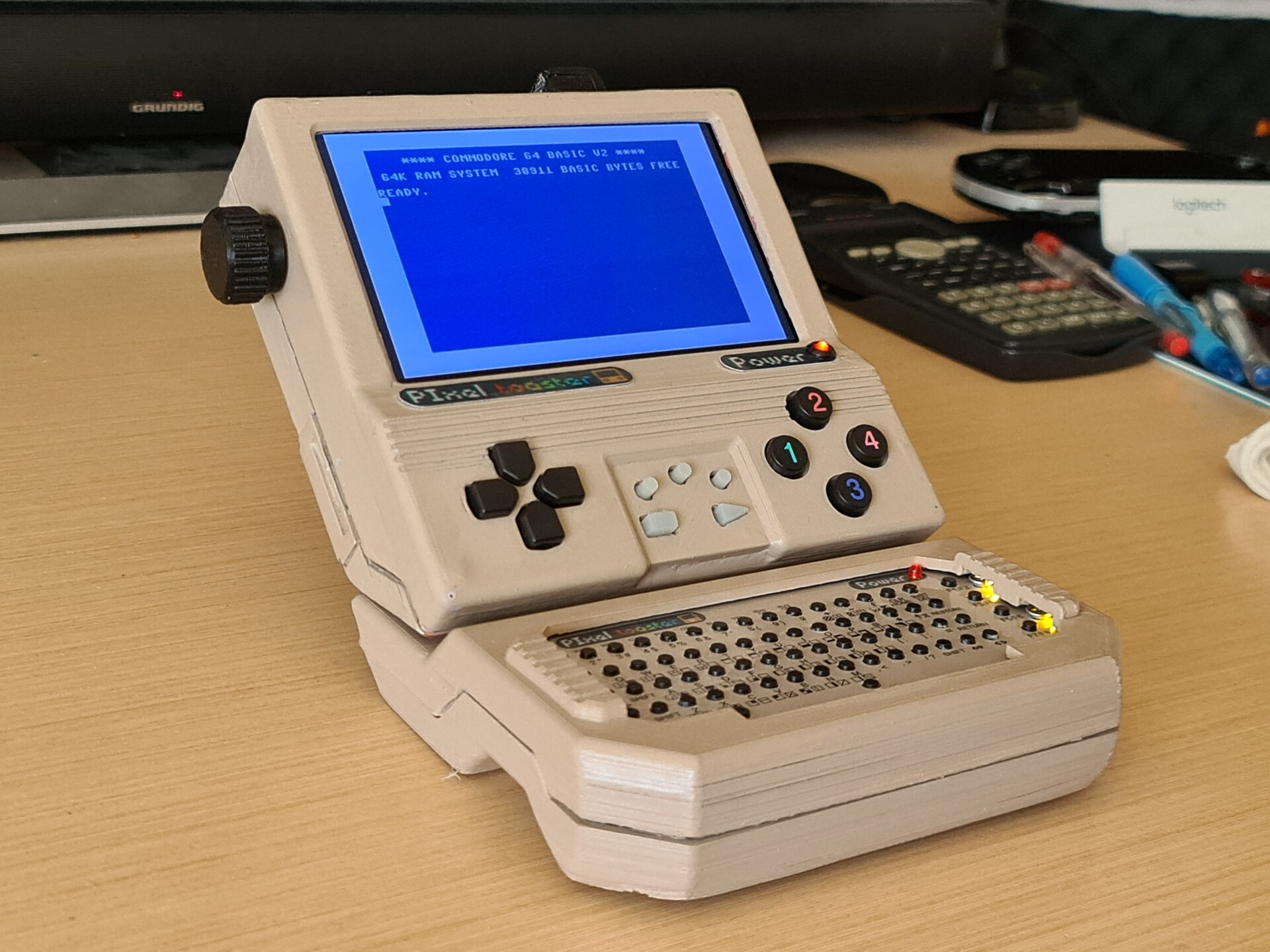
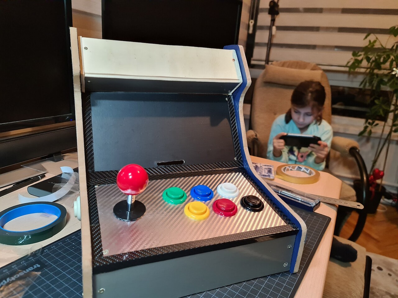
Hello, in this post I will show the progress of a mini arcade cabinet creation. This is not a regular arcade cabinet, it's more like the ones that called "table-top" designs. This is how it looks:

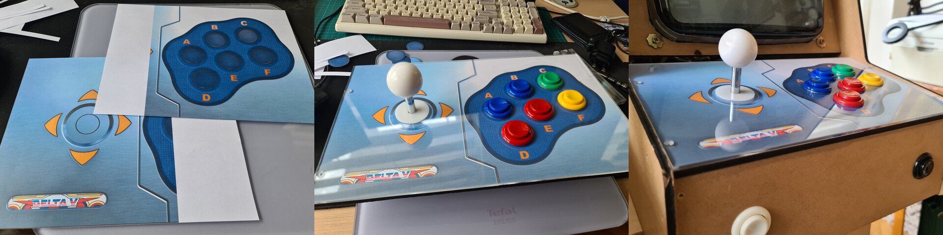
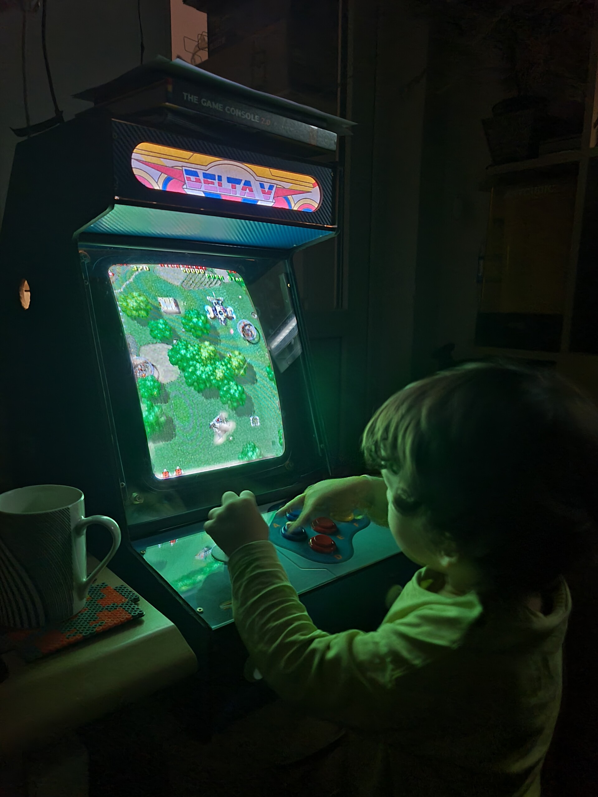
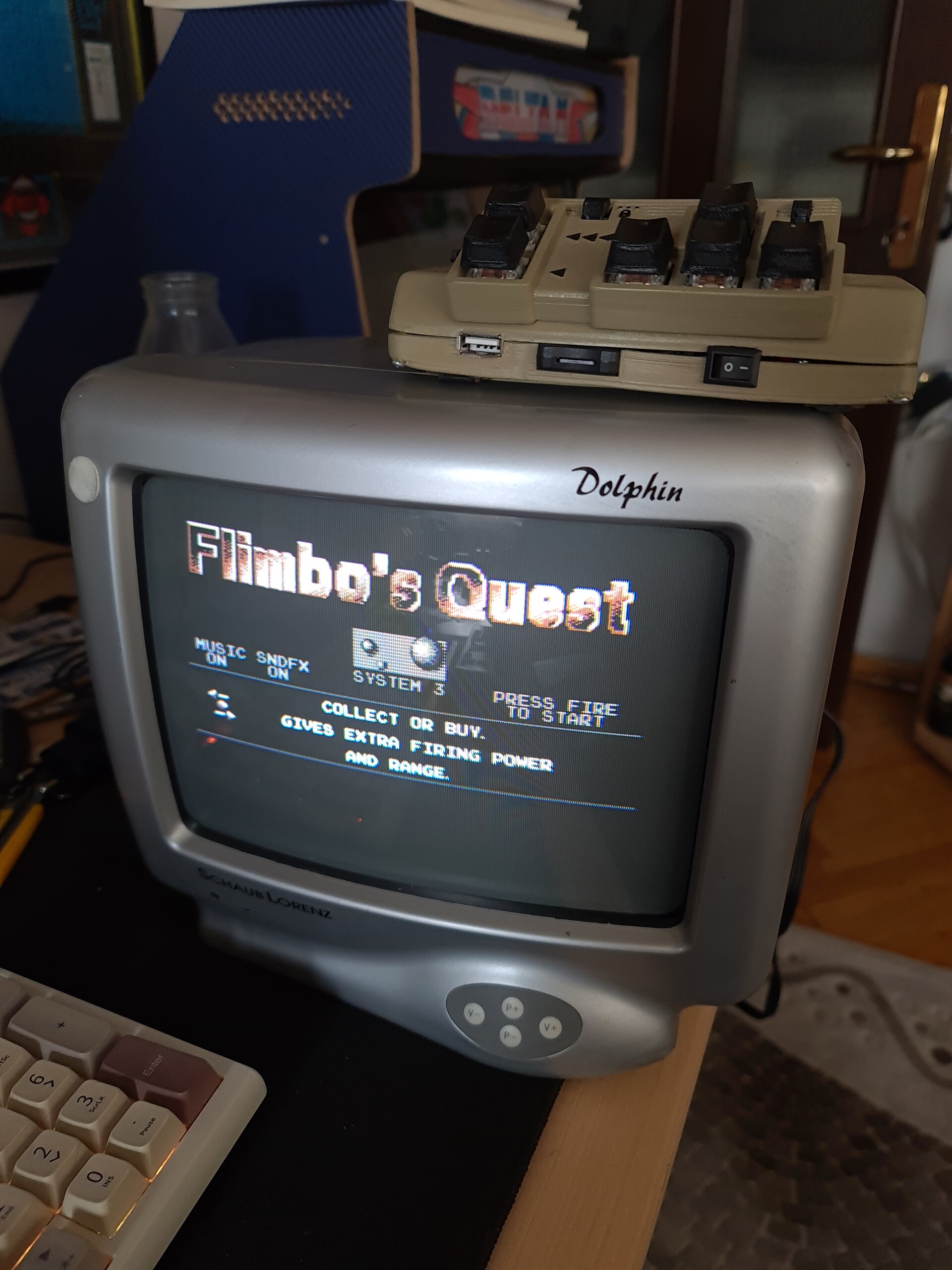
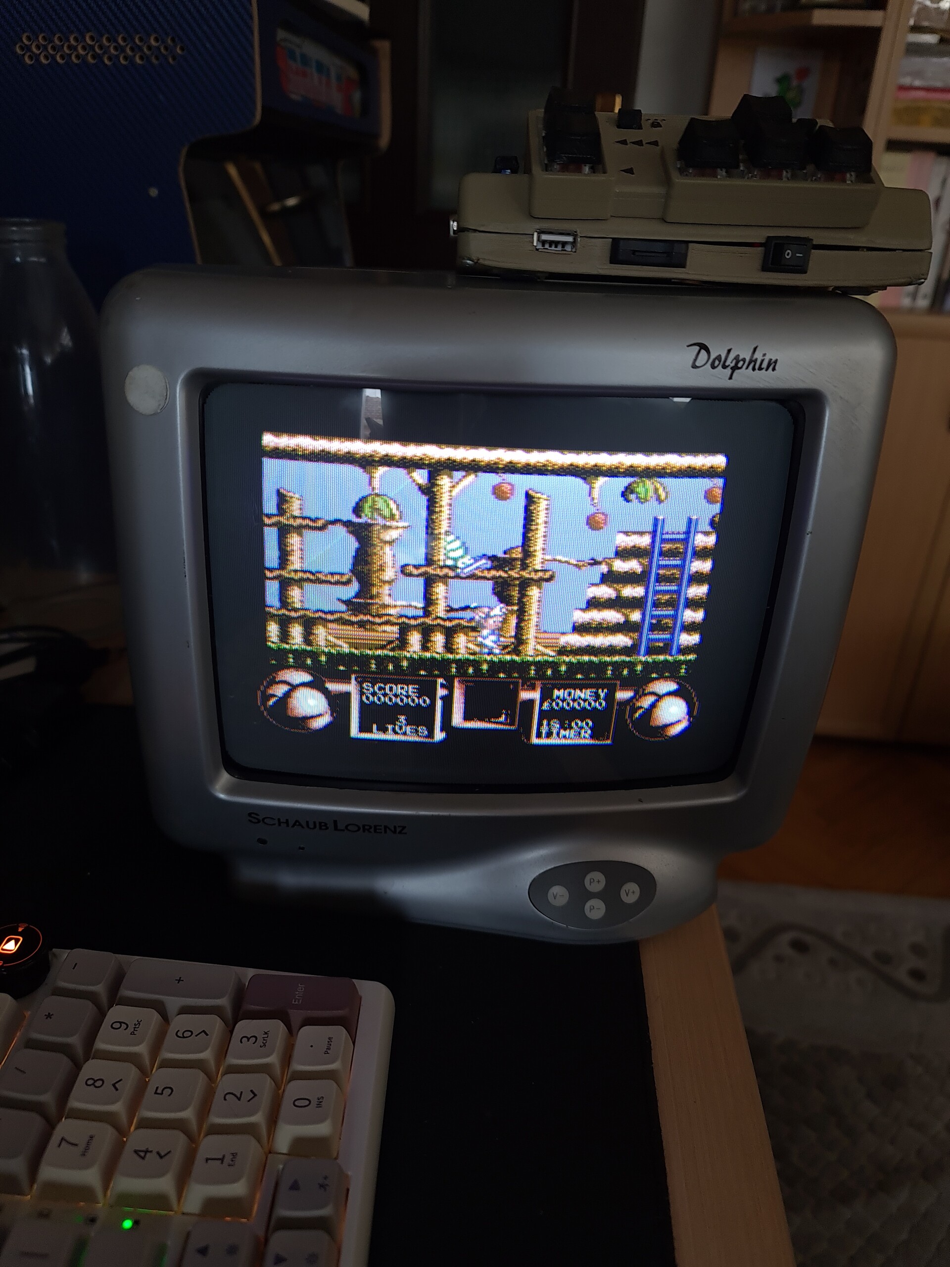
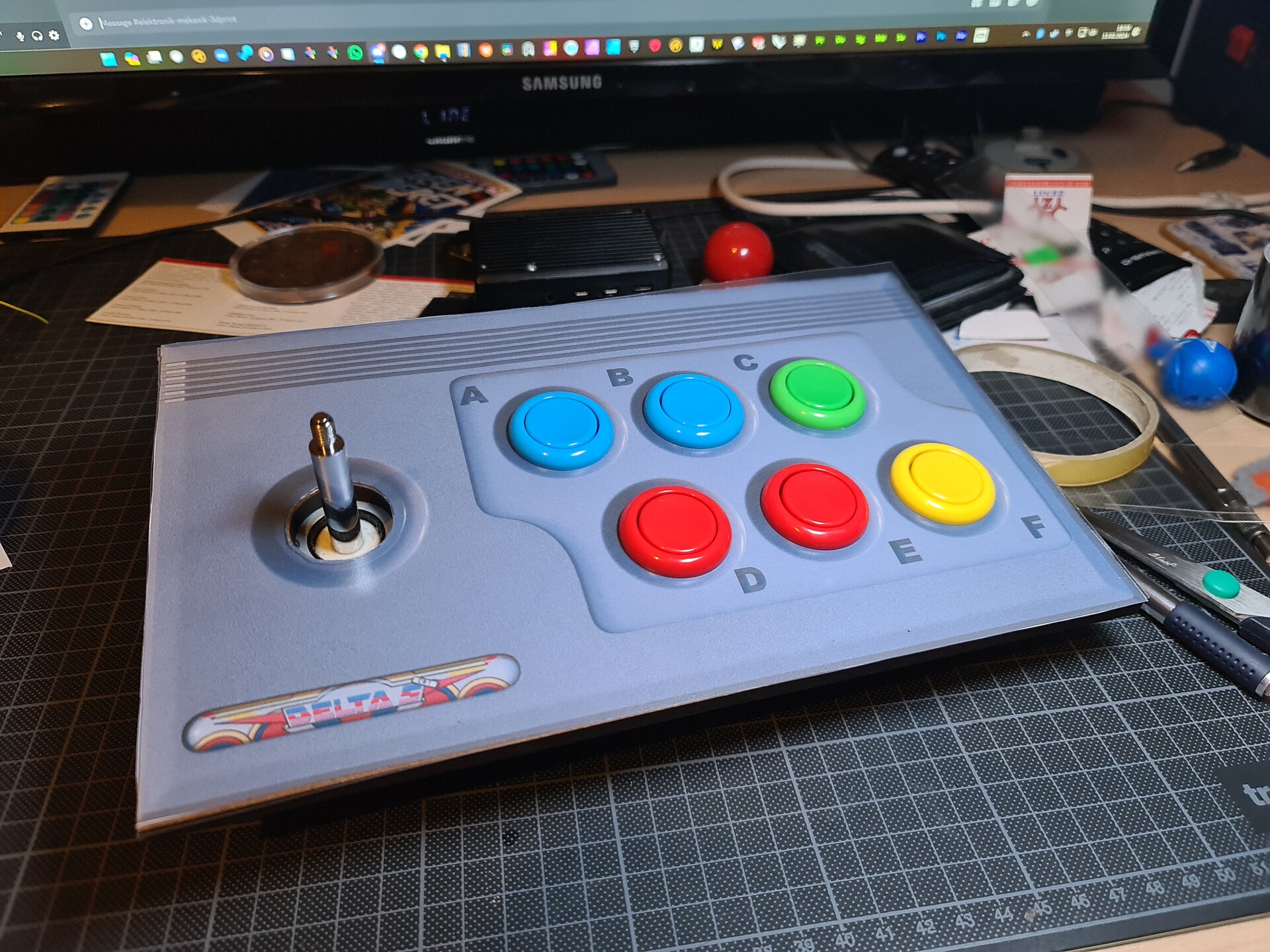
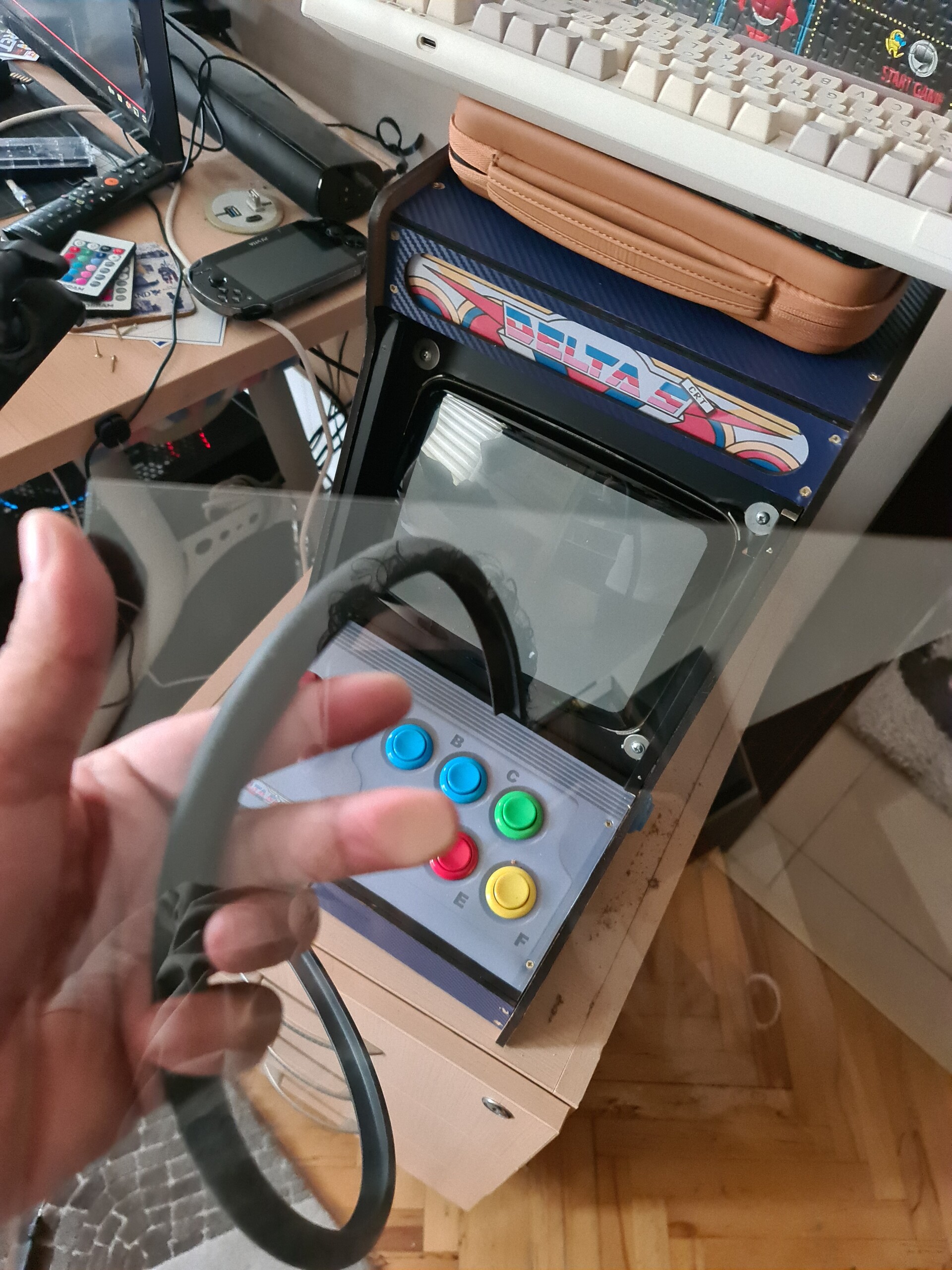
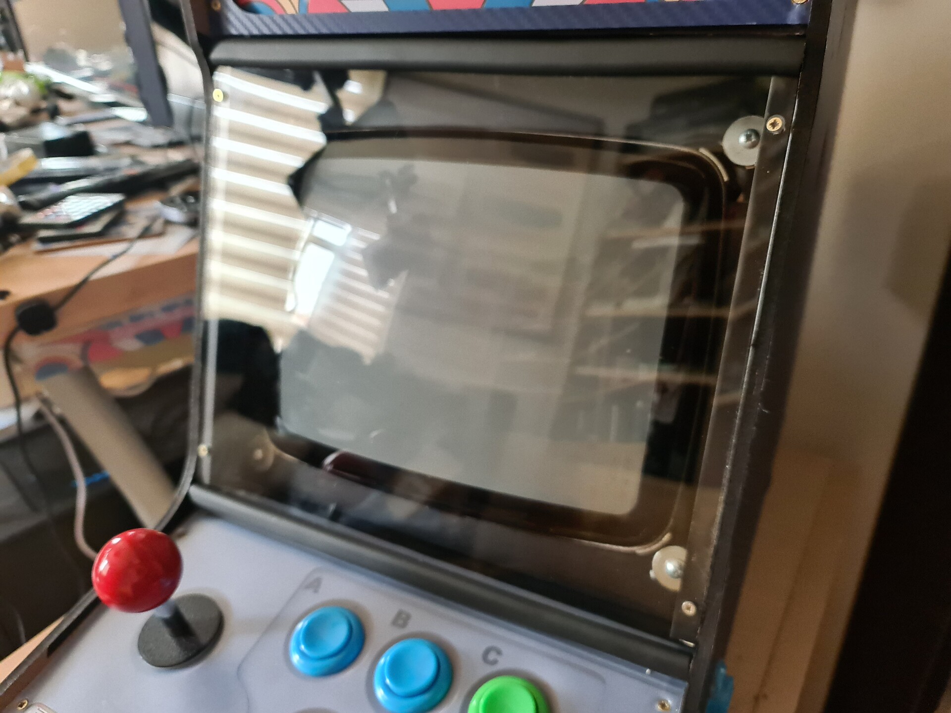
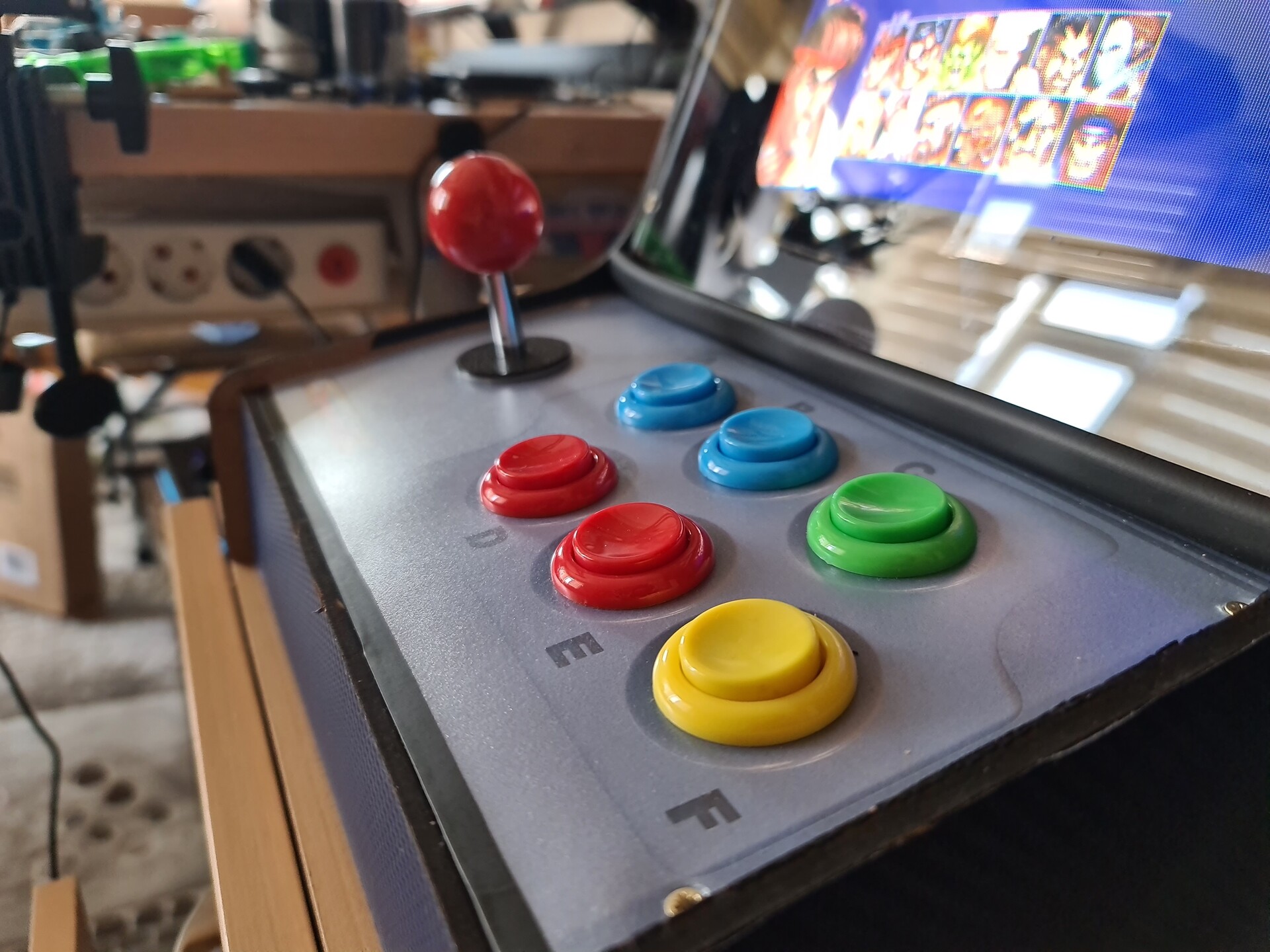
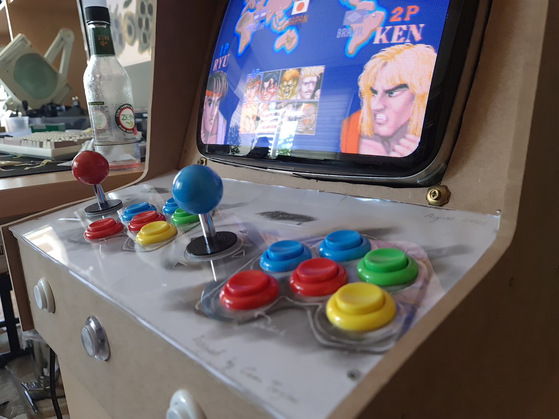
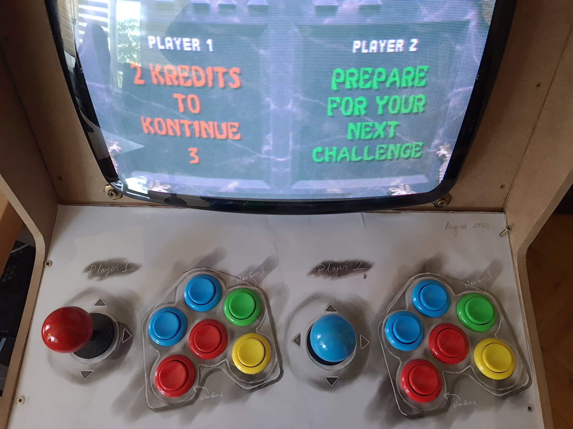
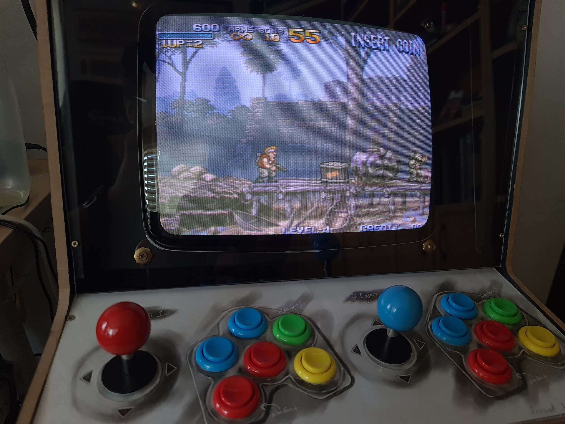
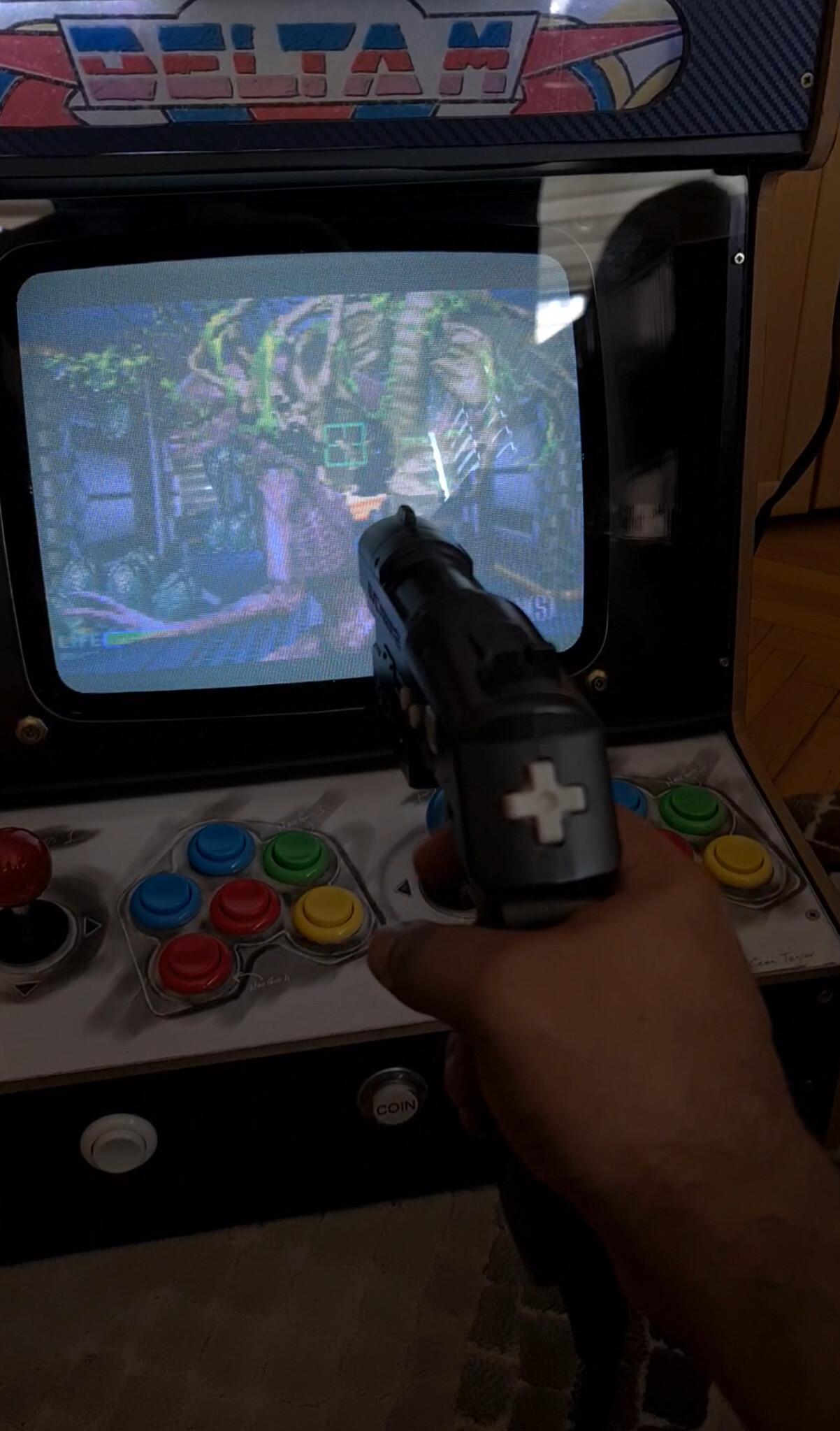
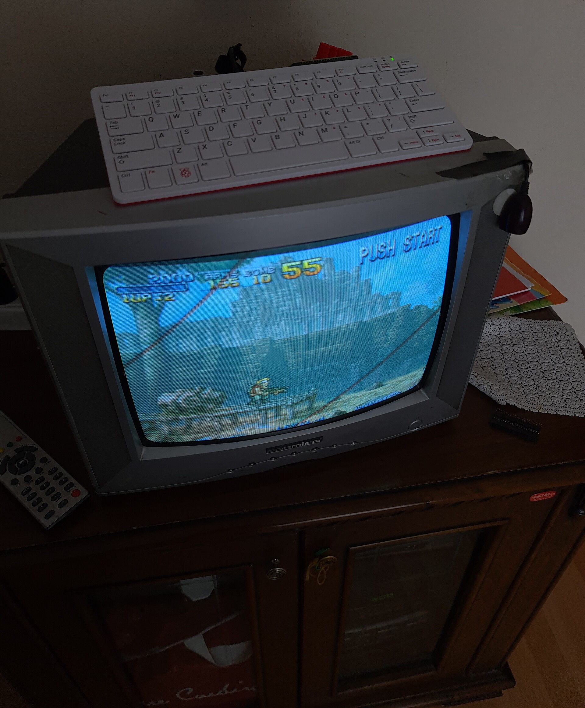
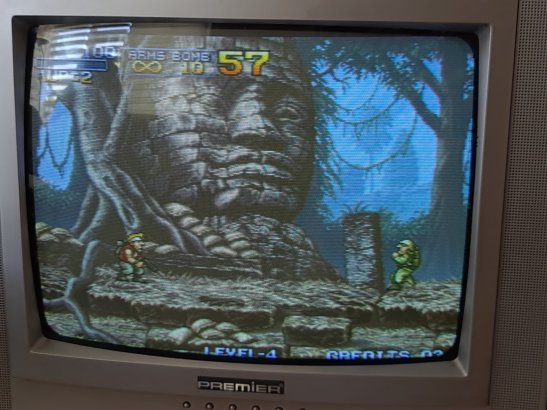
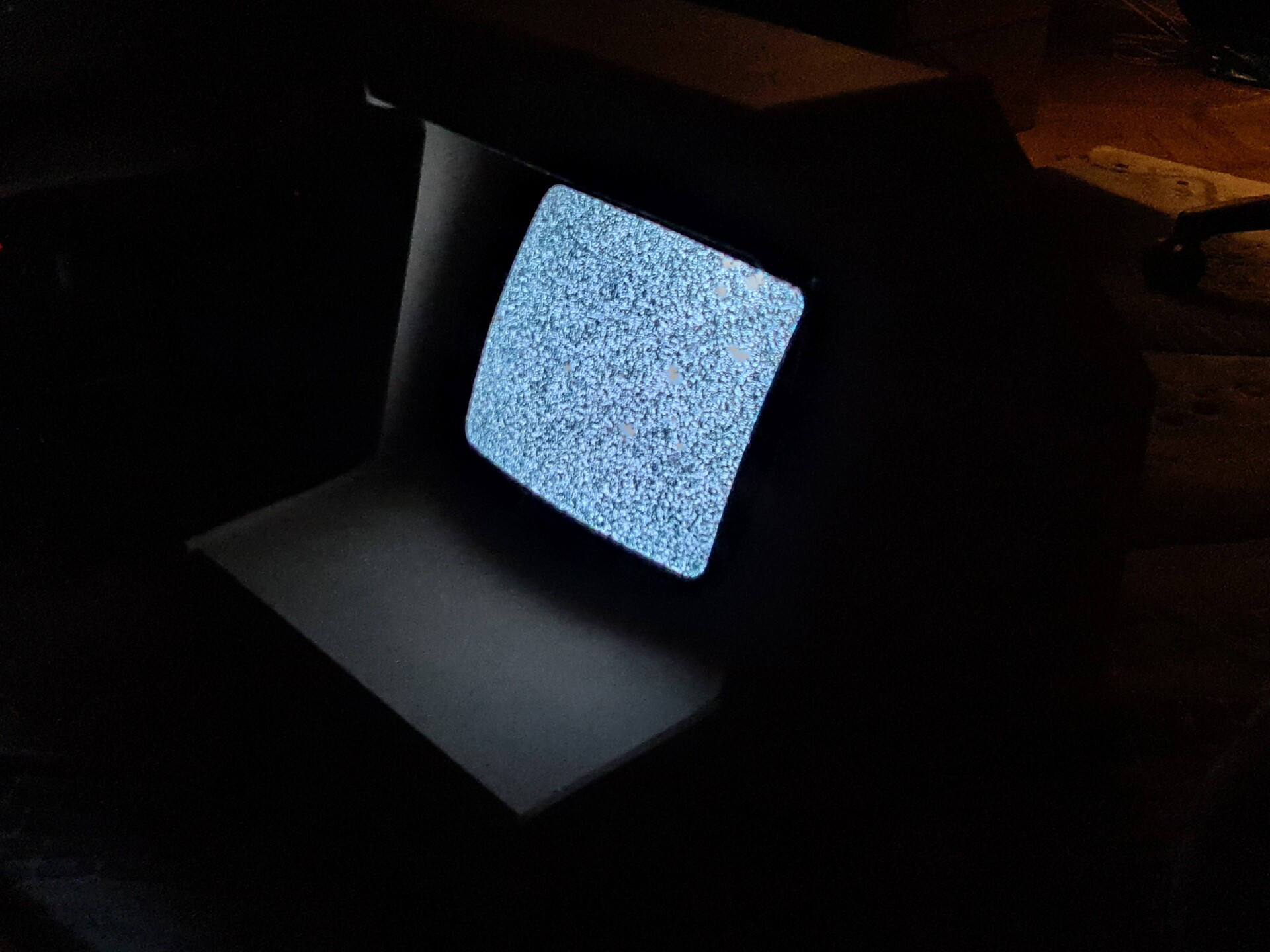
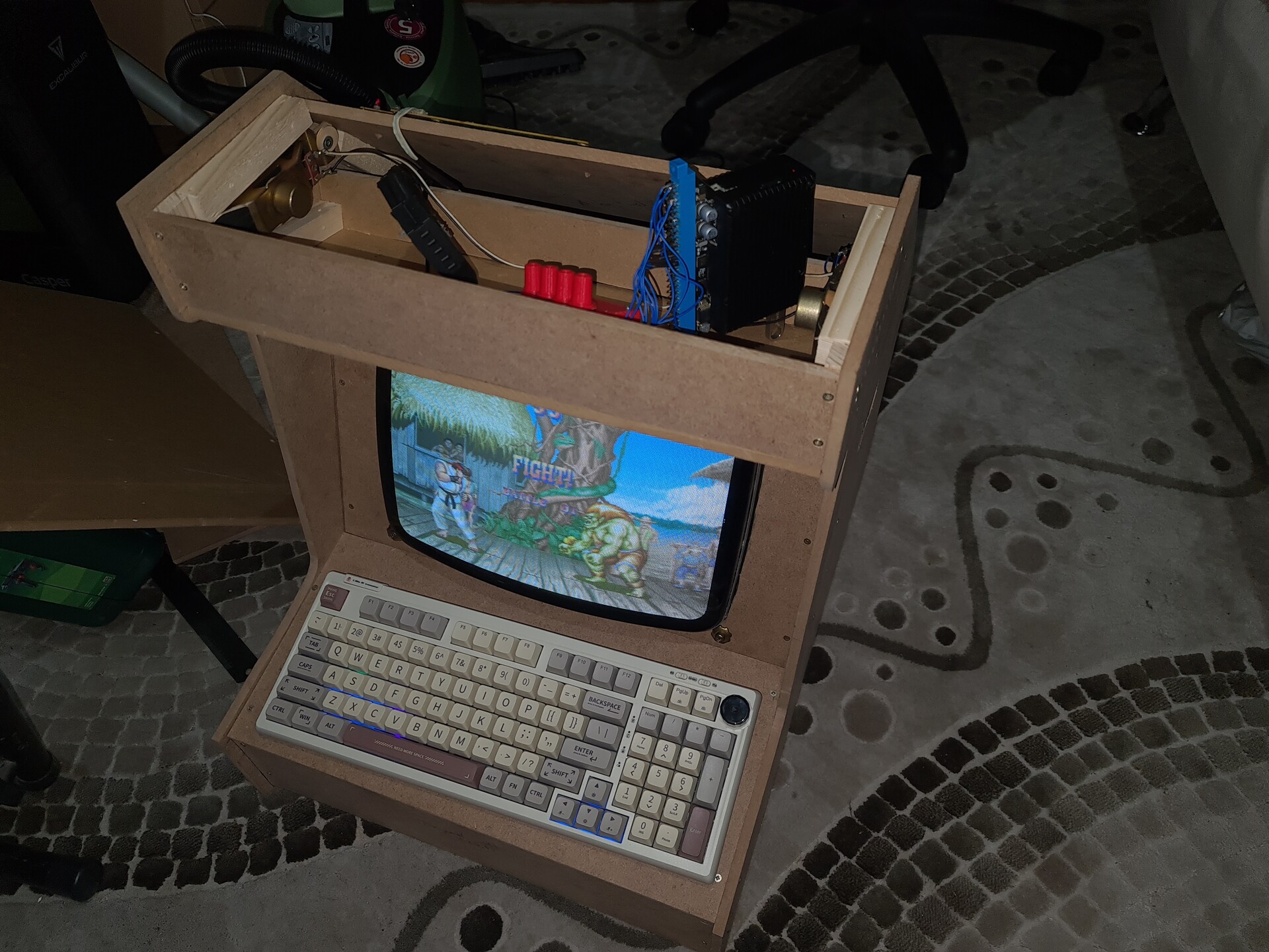
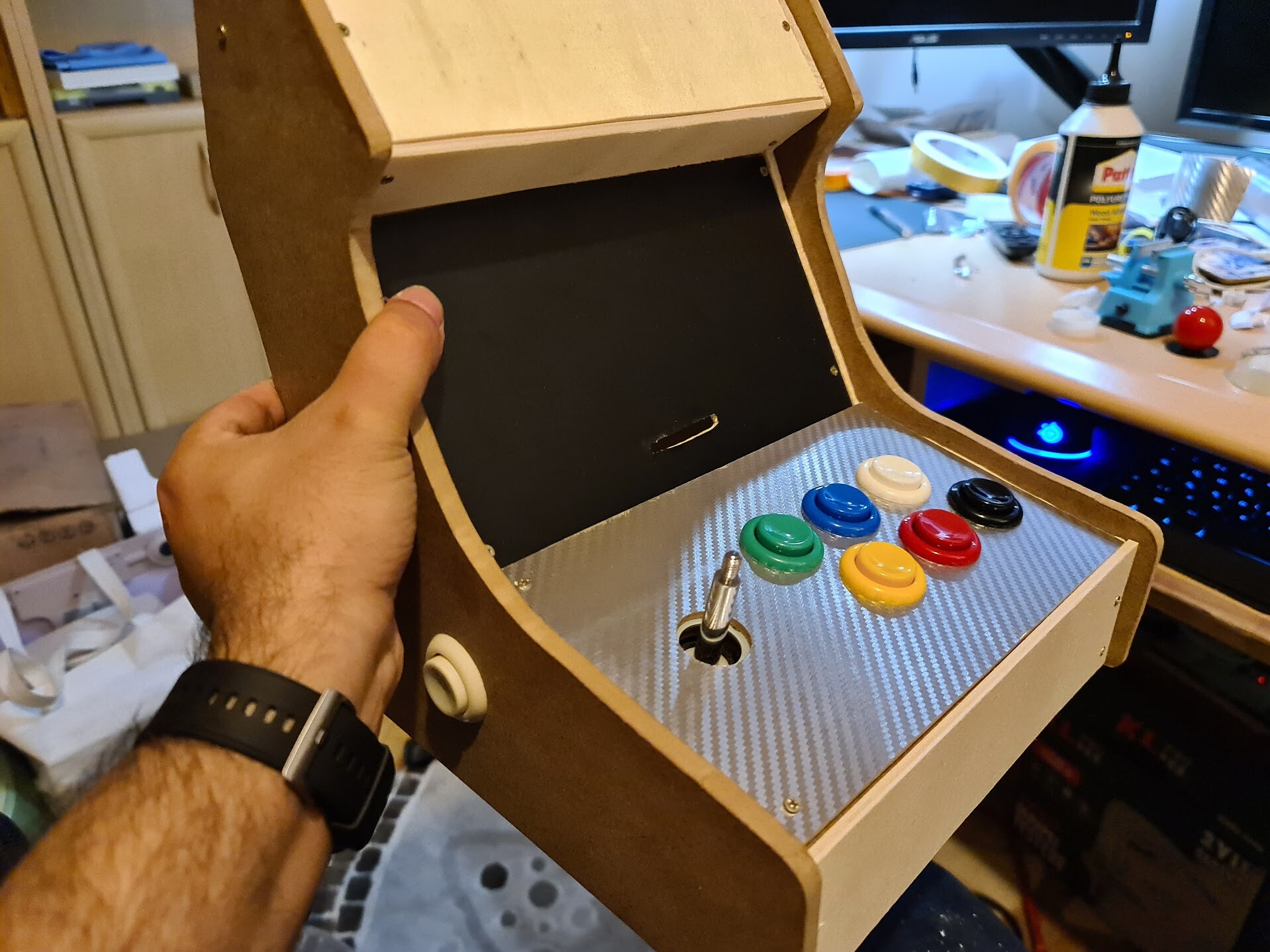
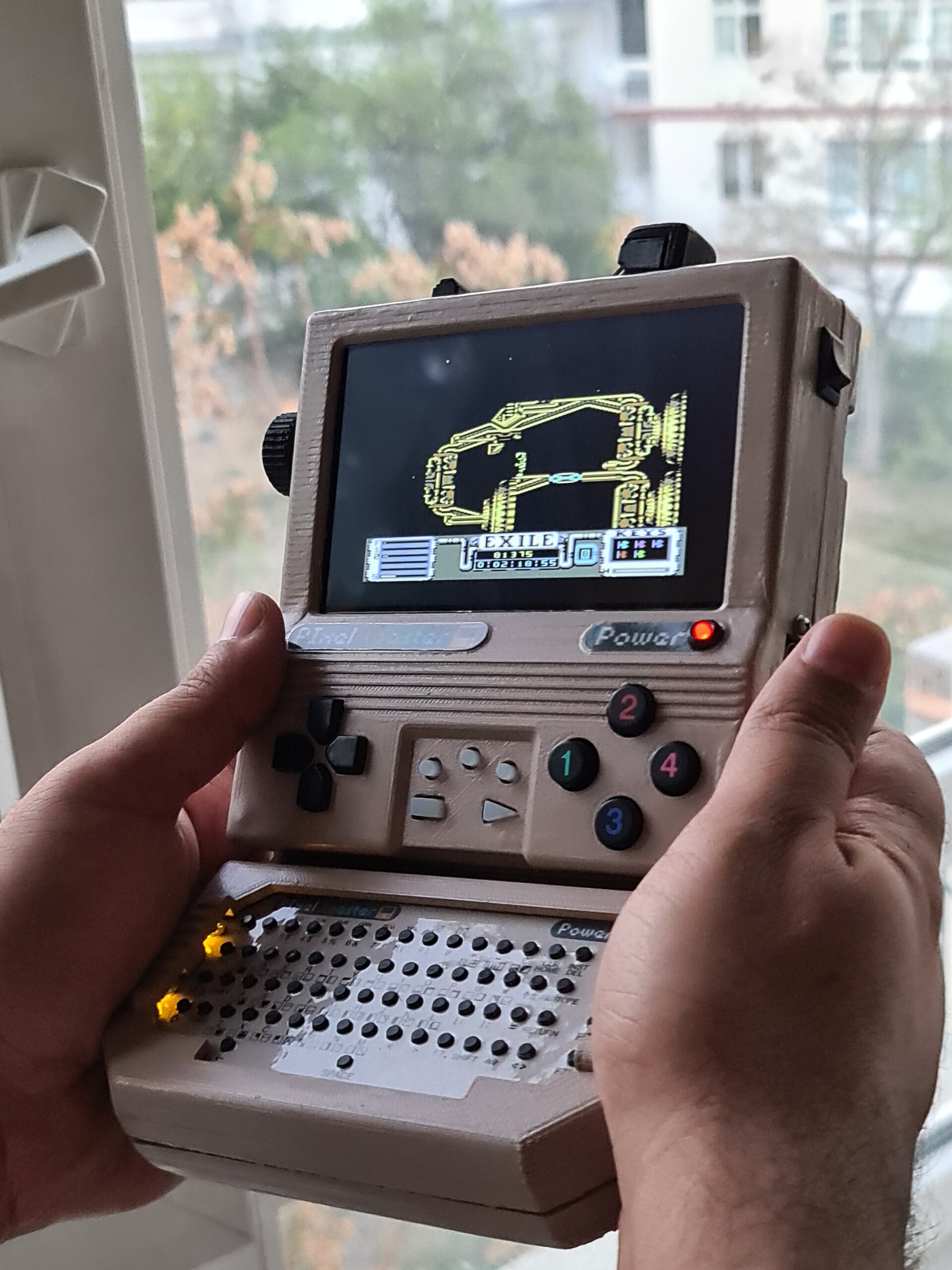
And this is how it's played by:


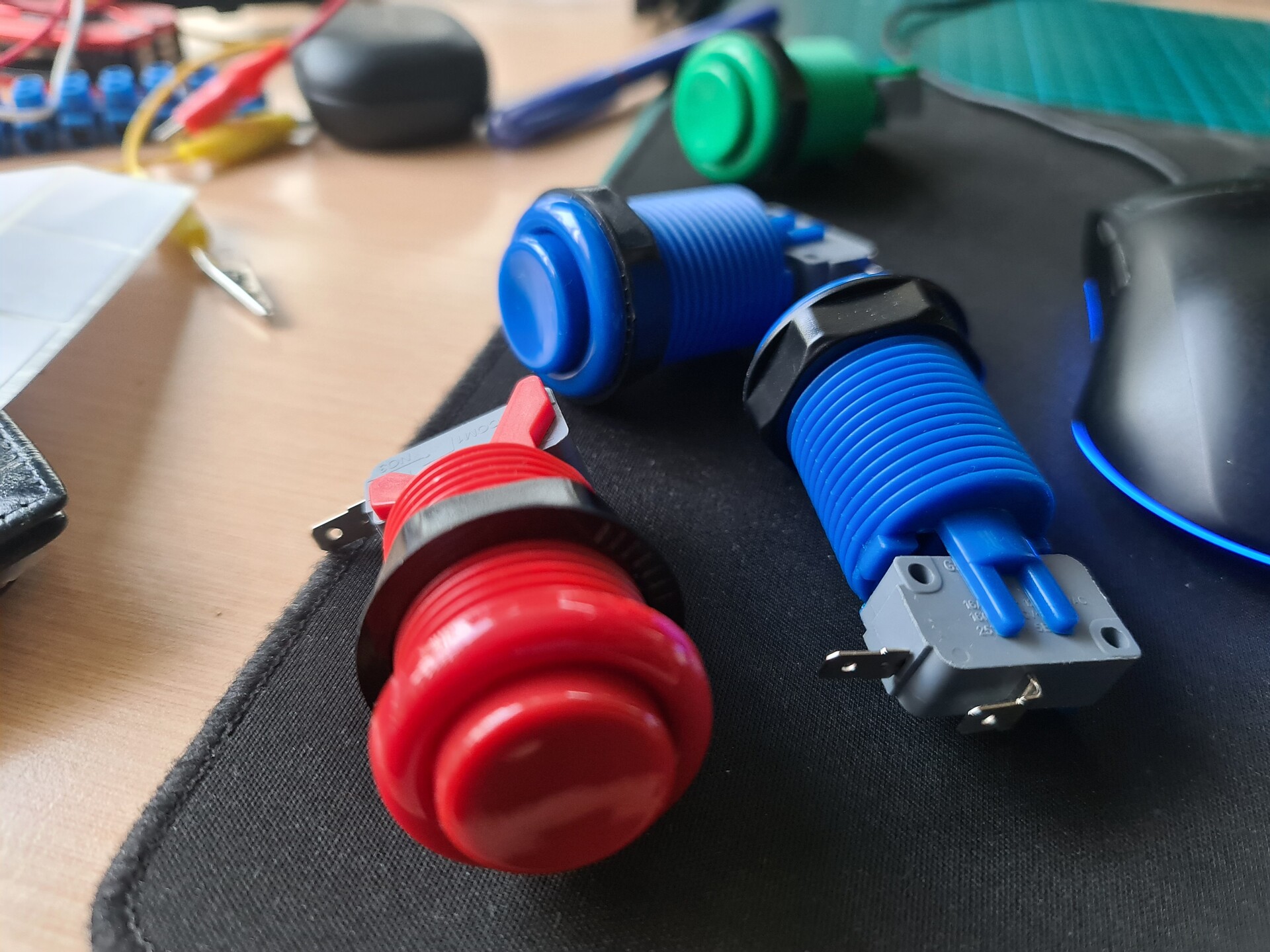
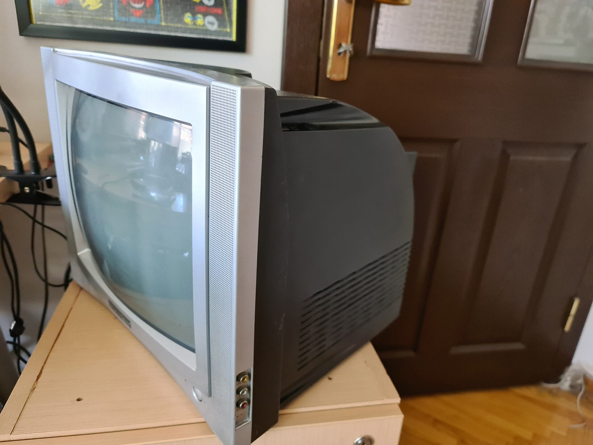
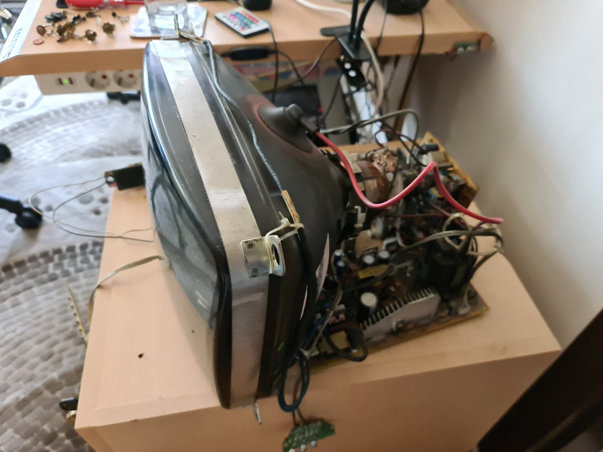
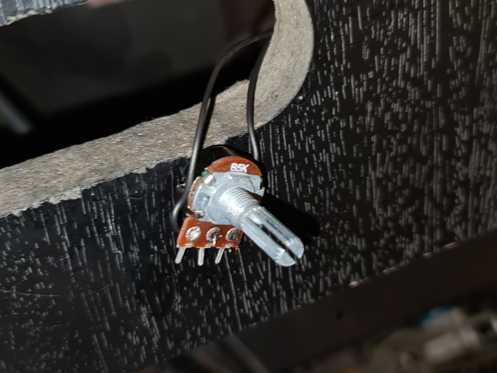
The idea has came from that I had some spare buttons and joysticks when I used on the real arcade cabinet that I acquired. So with that spare parts and more importantly the 7" screen that I had for long time, I decided to assemble a mini cabinet with a Raspberry Pi. 

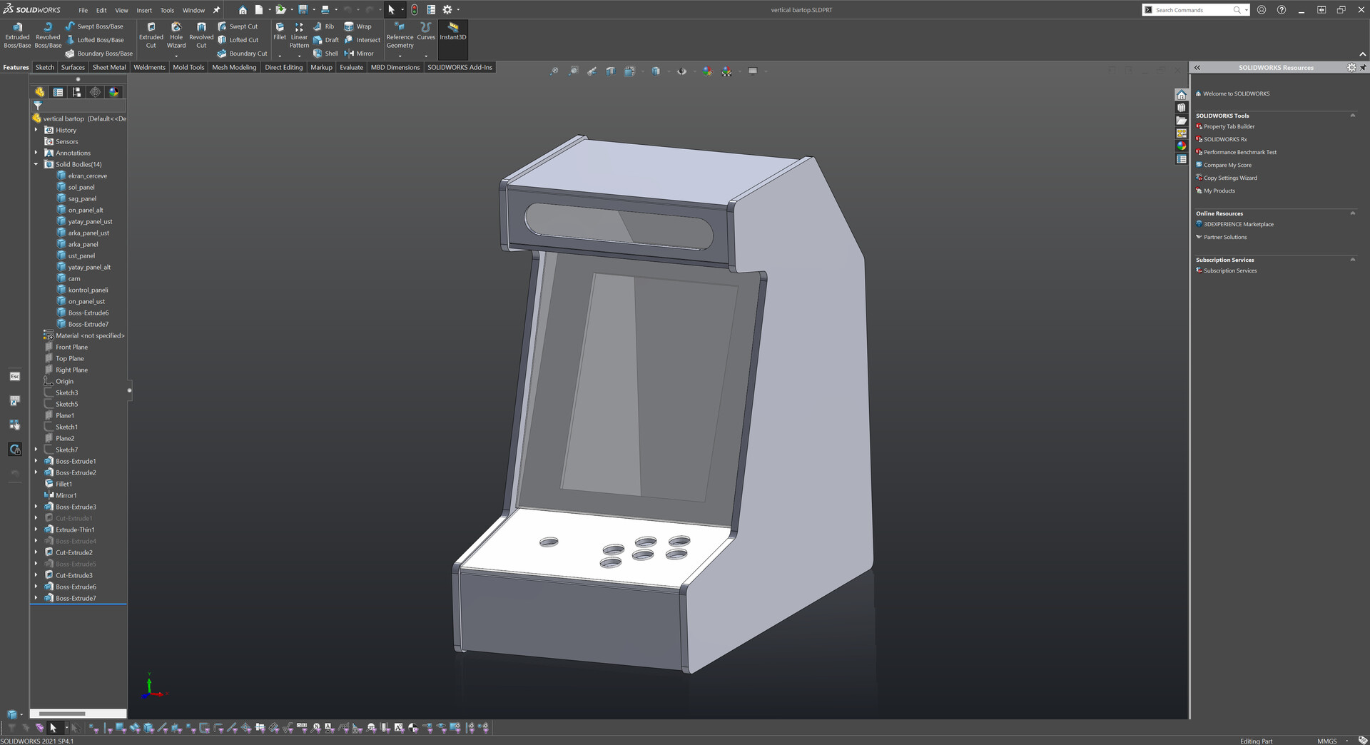
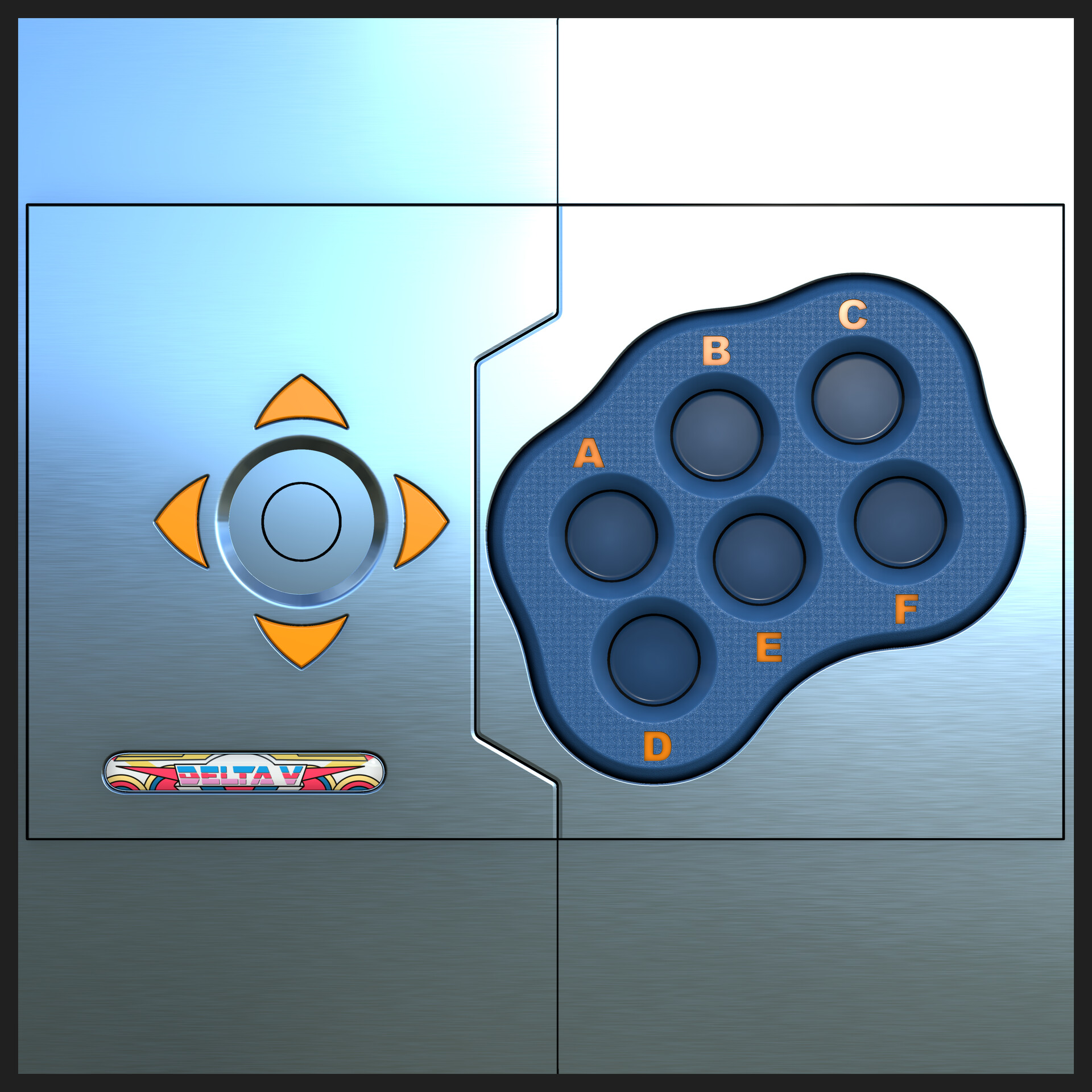
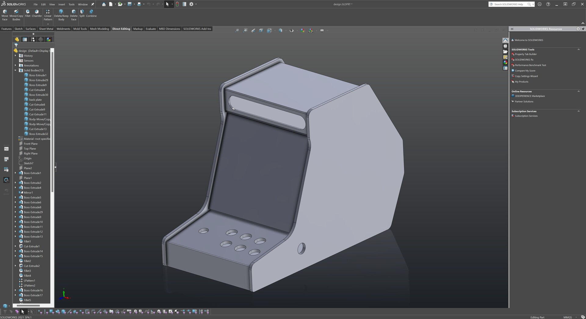
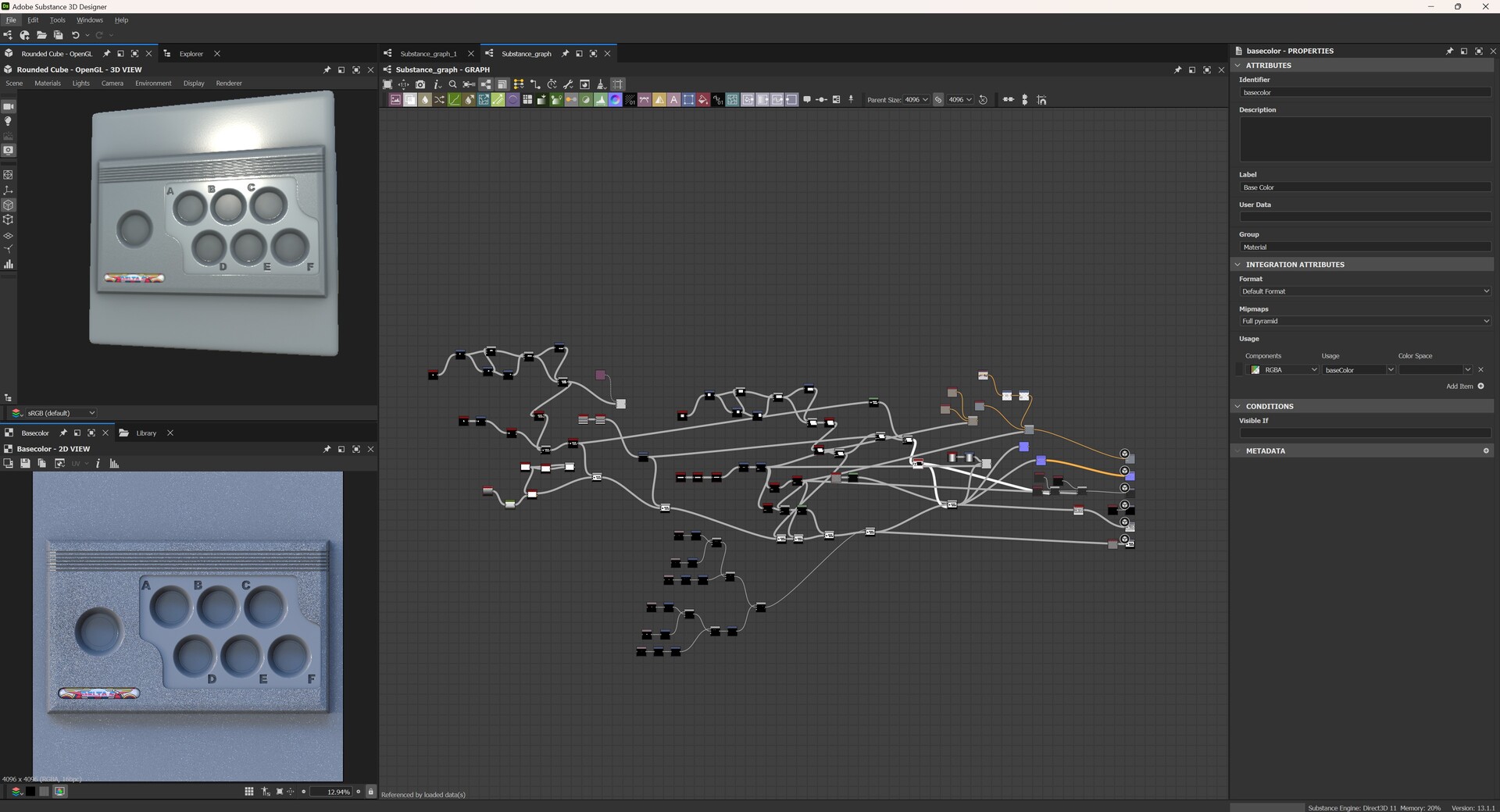
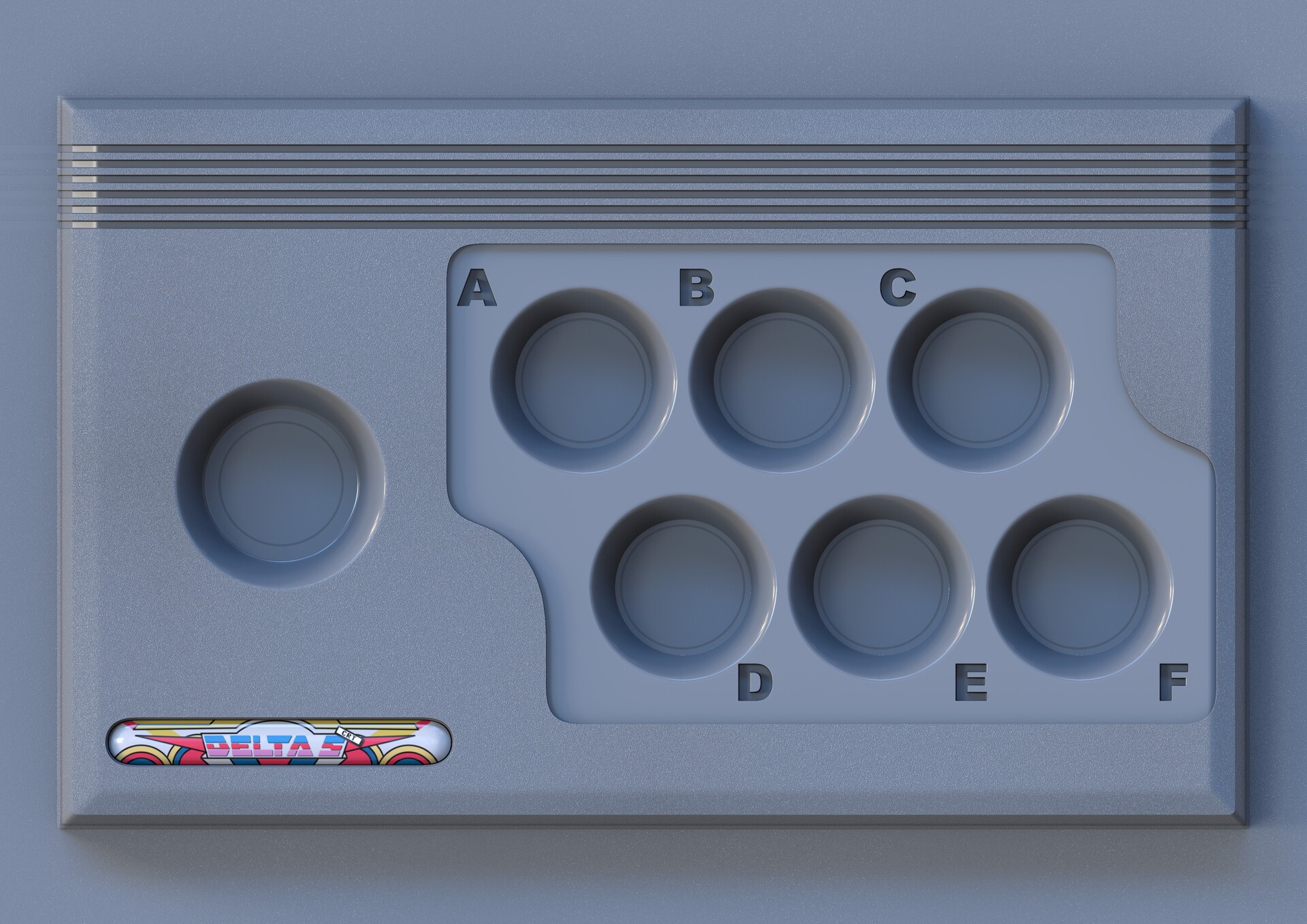
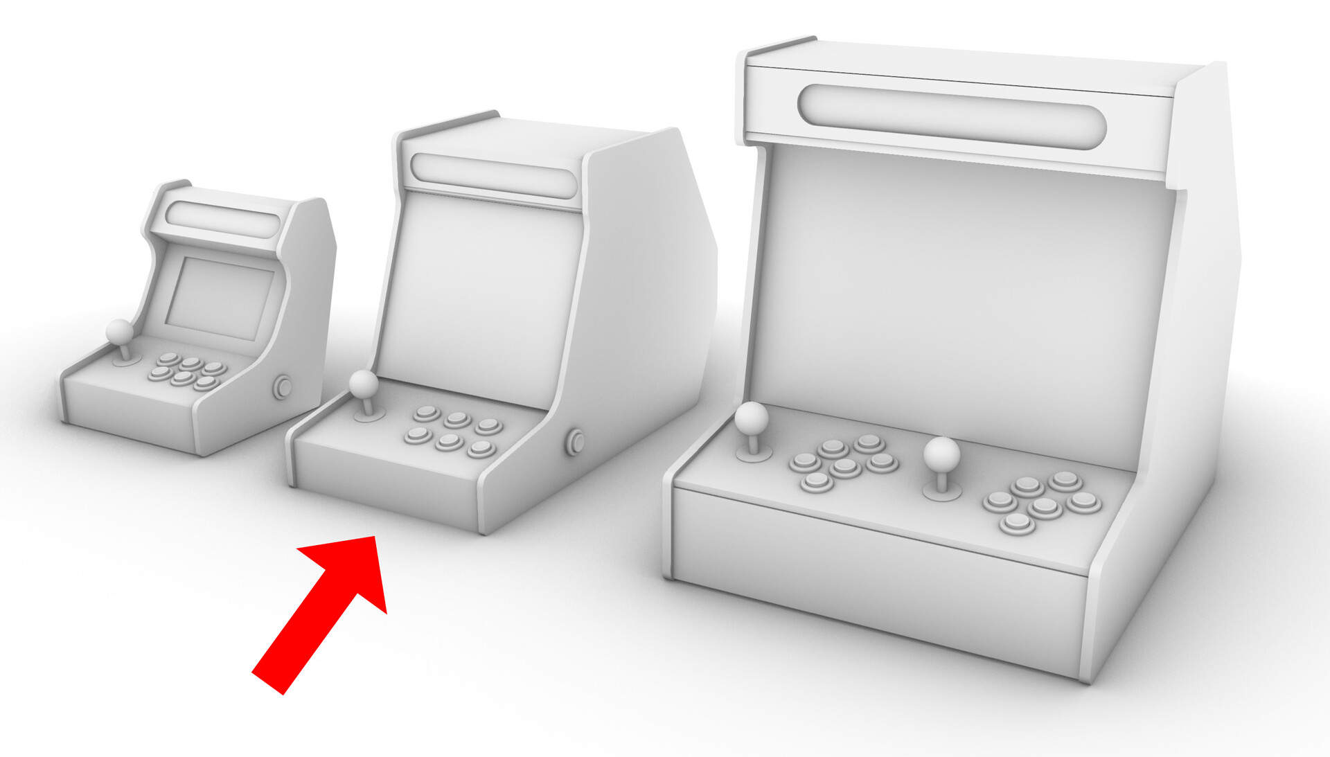
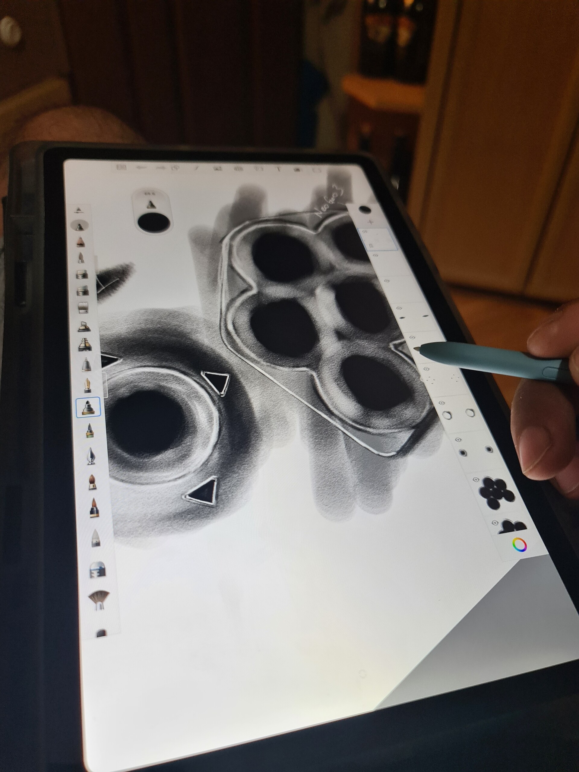
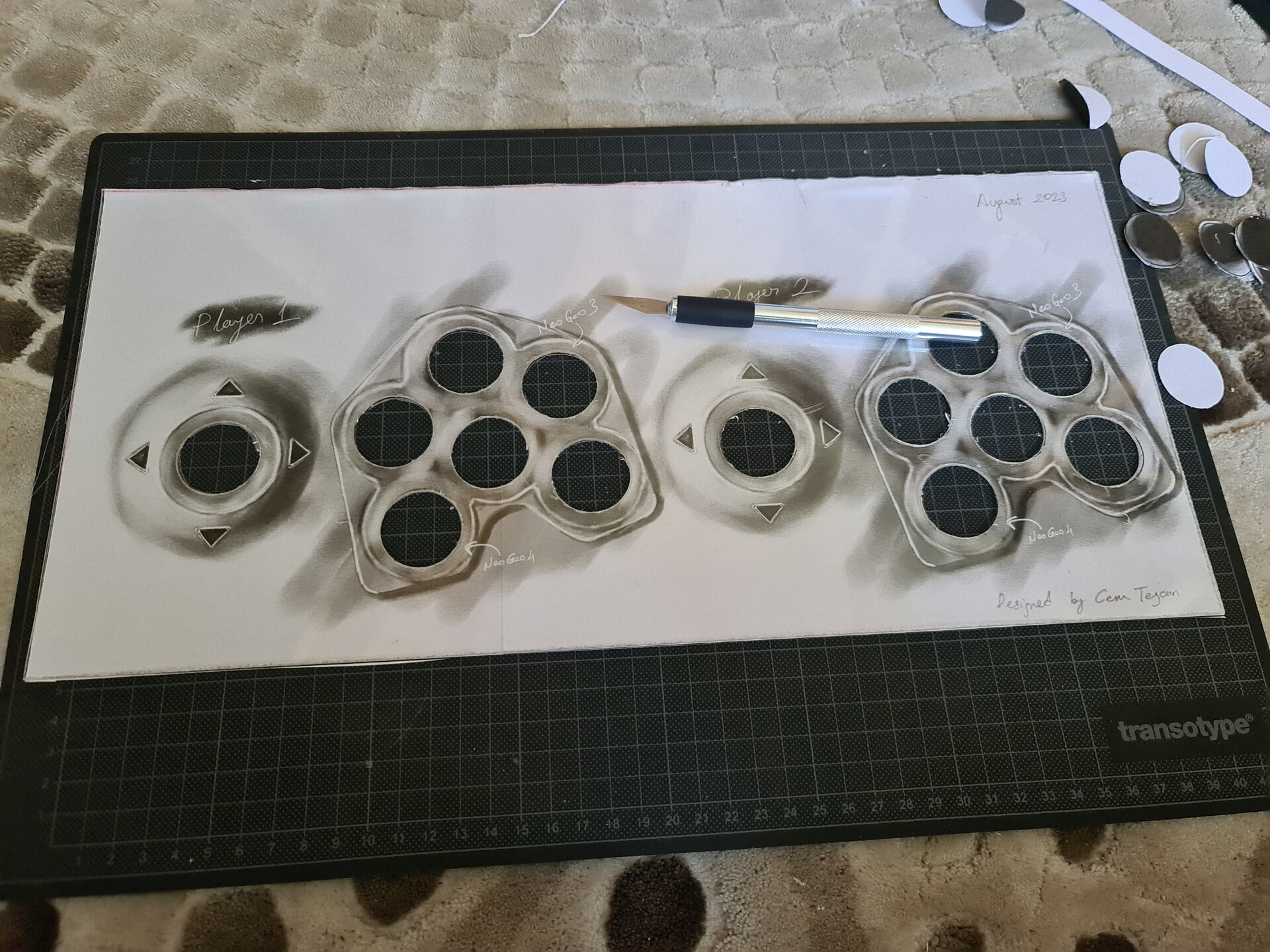
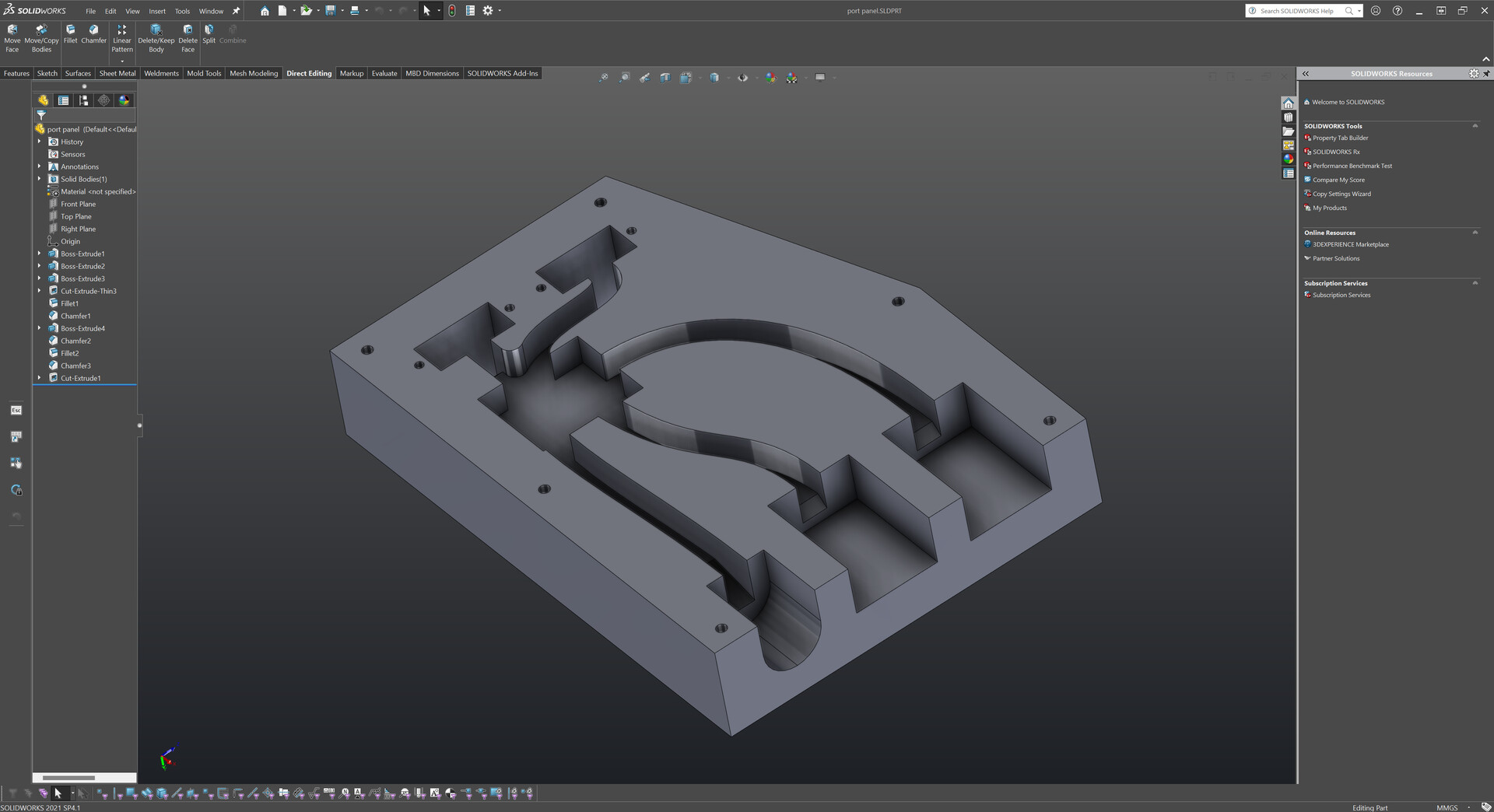
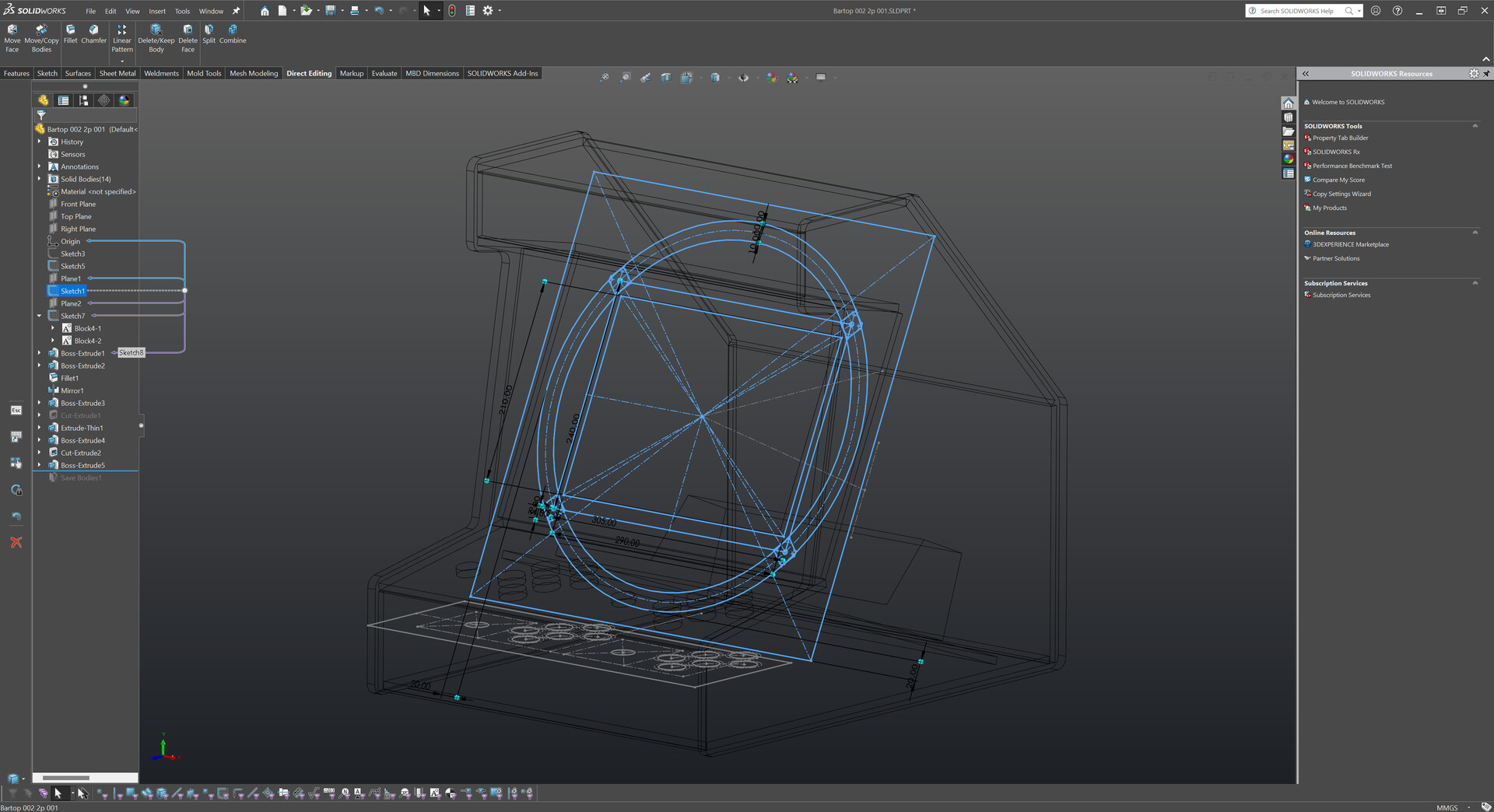
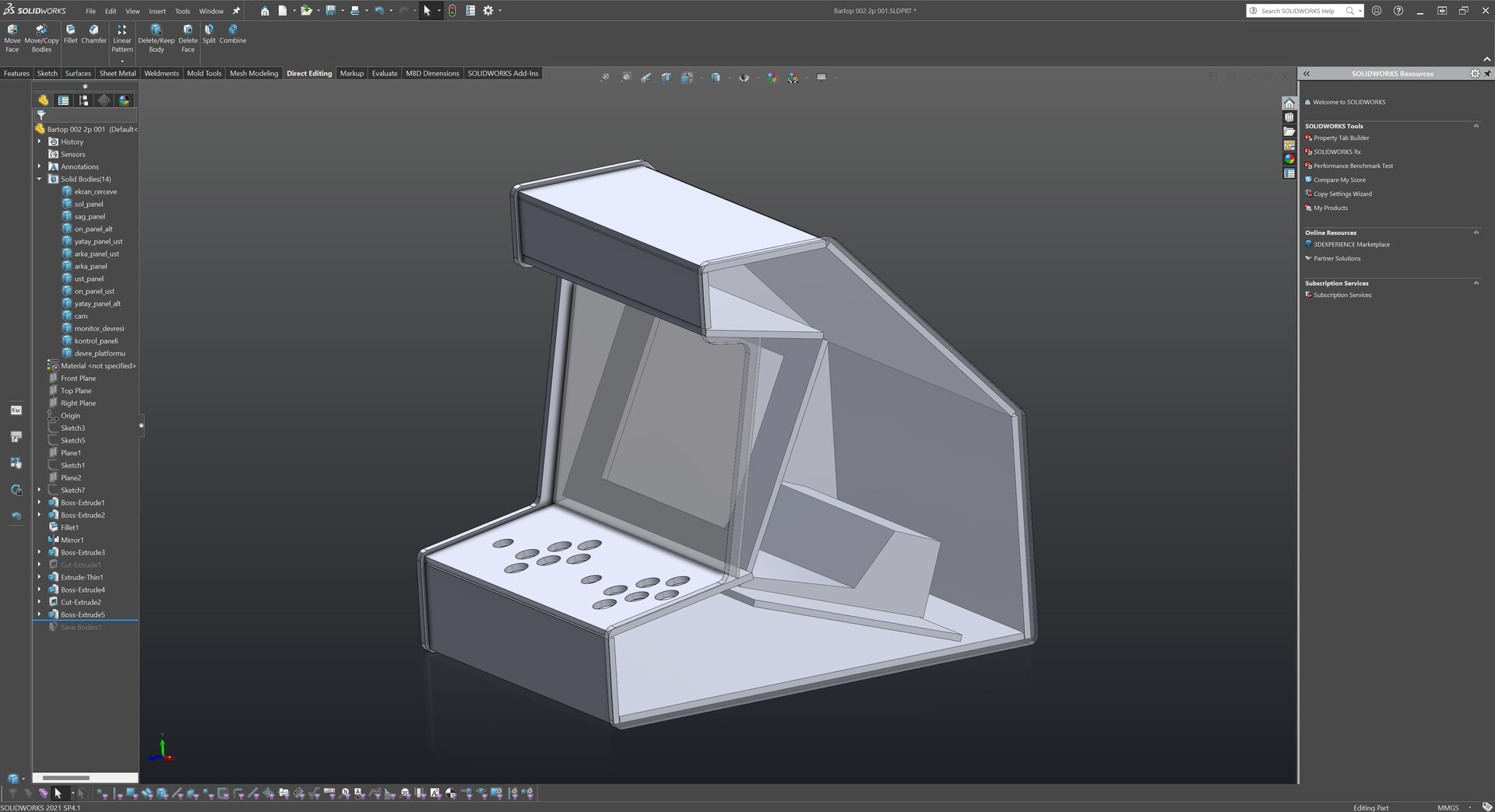
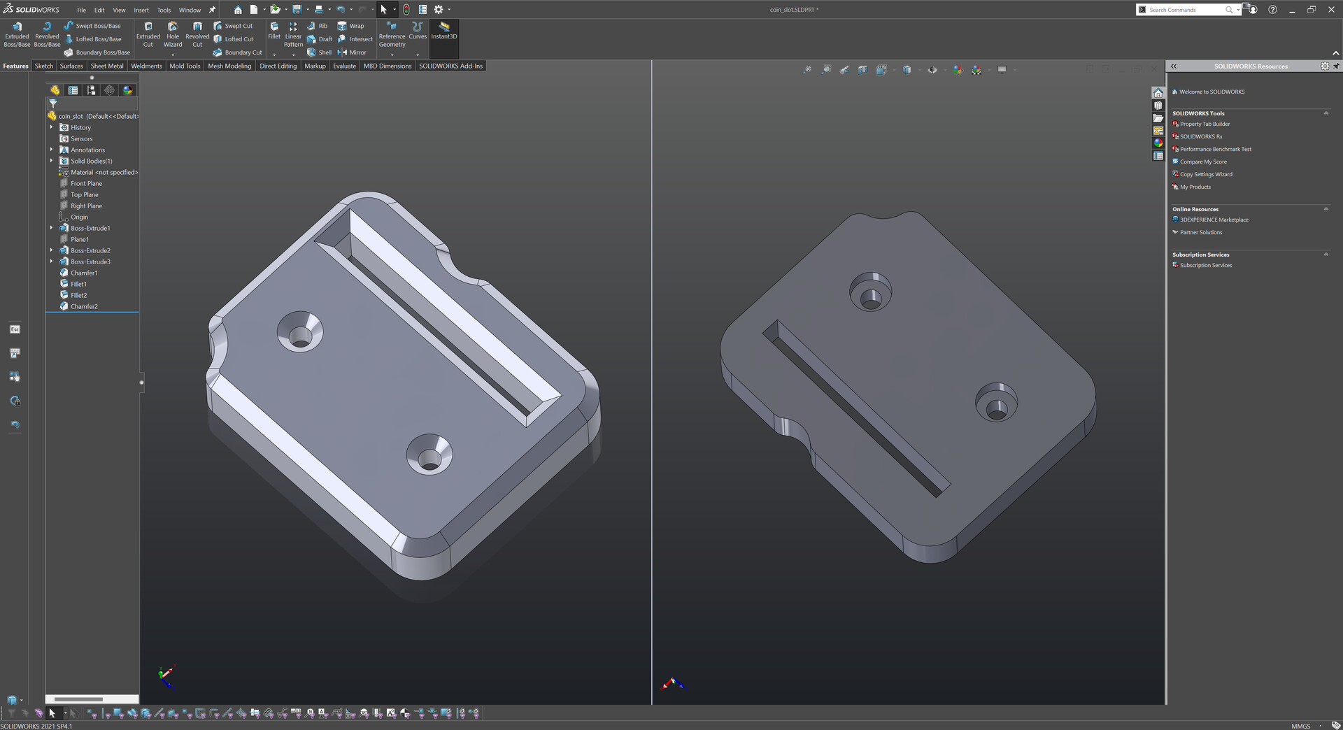
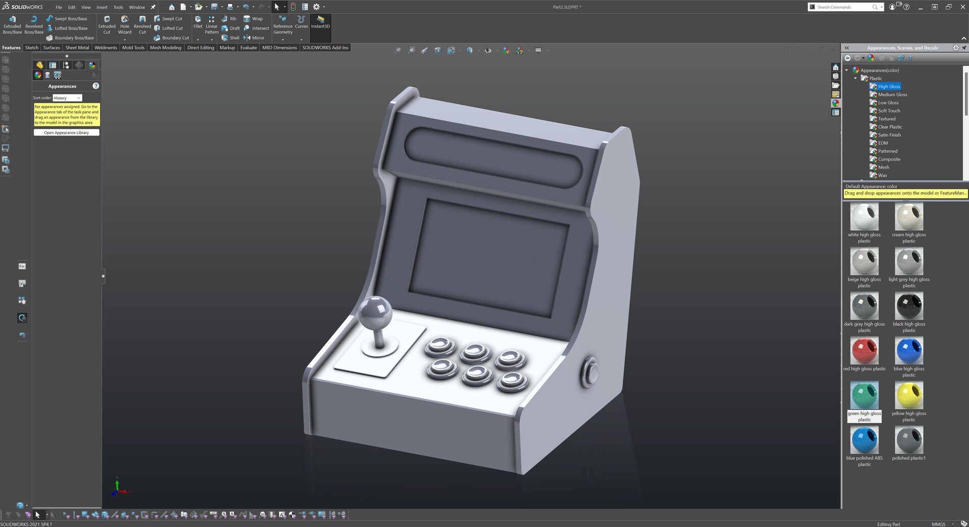
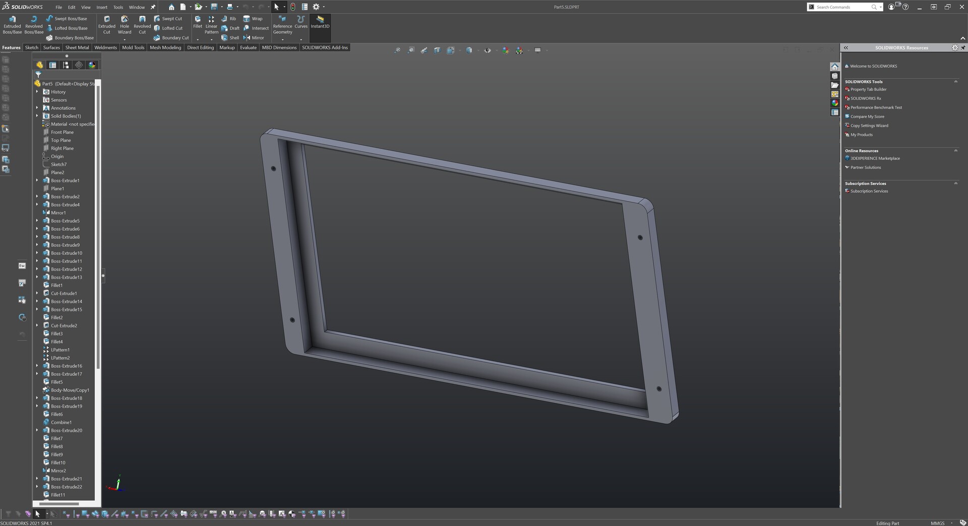
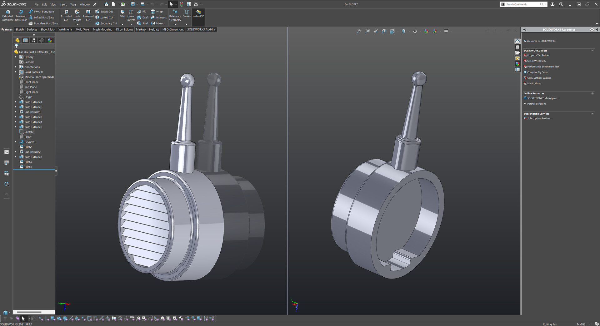
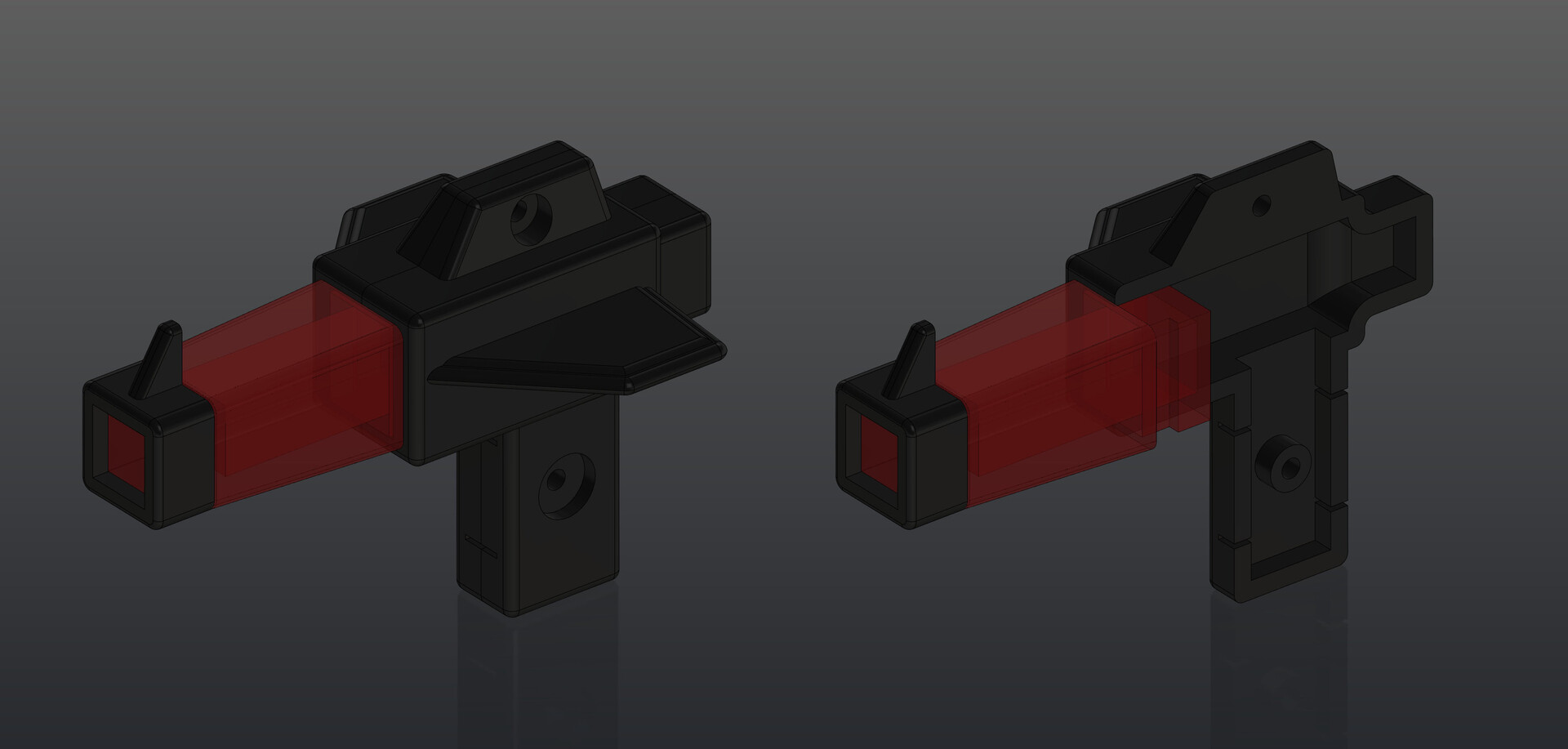
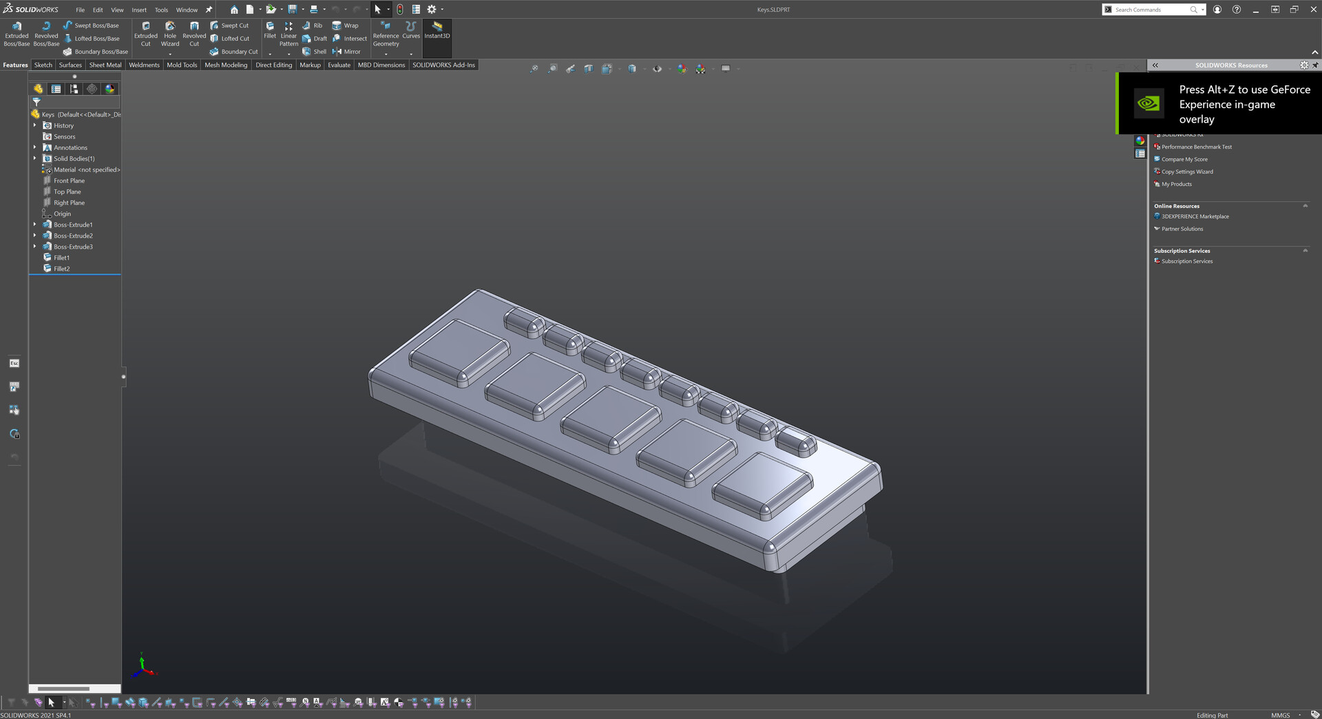
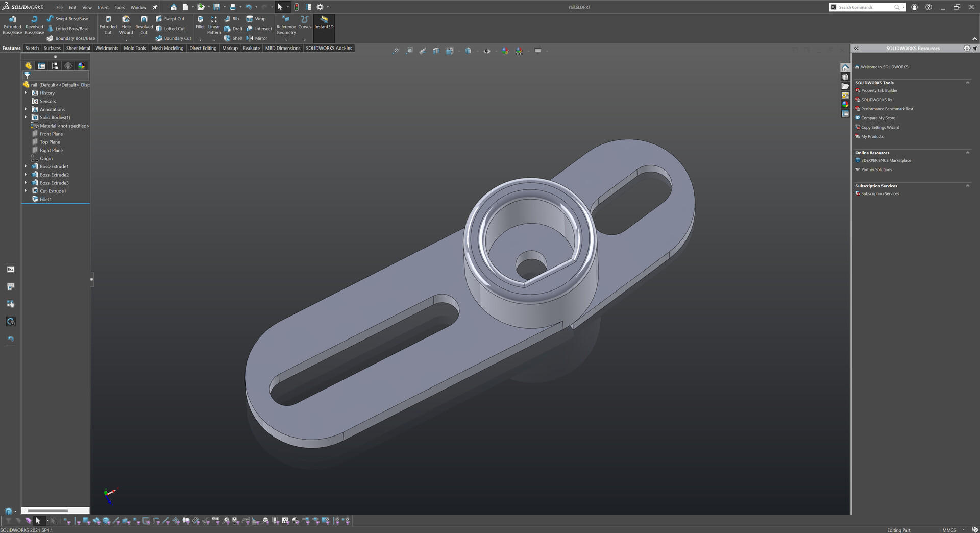
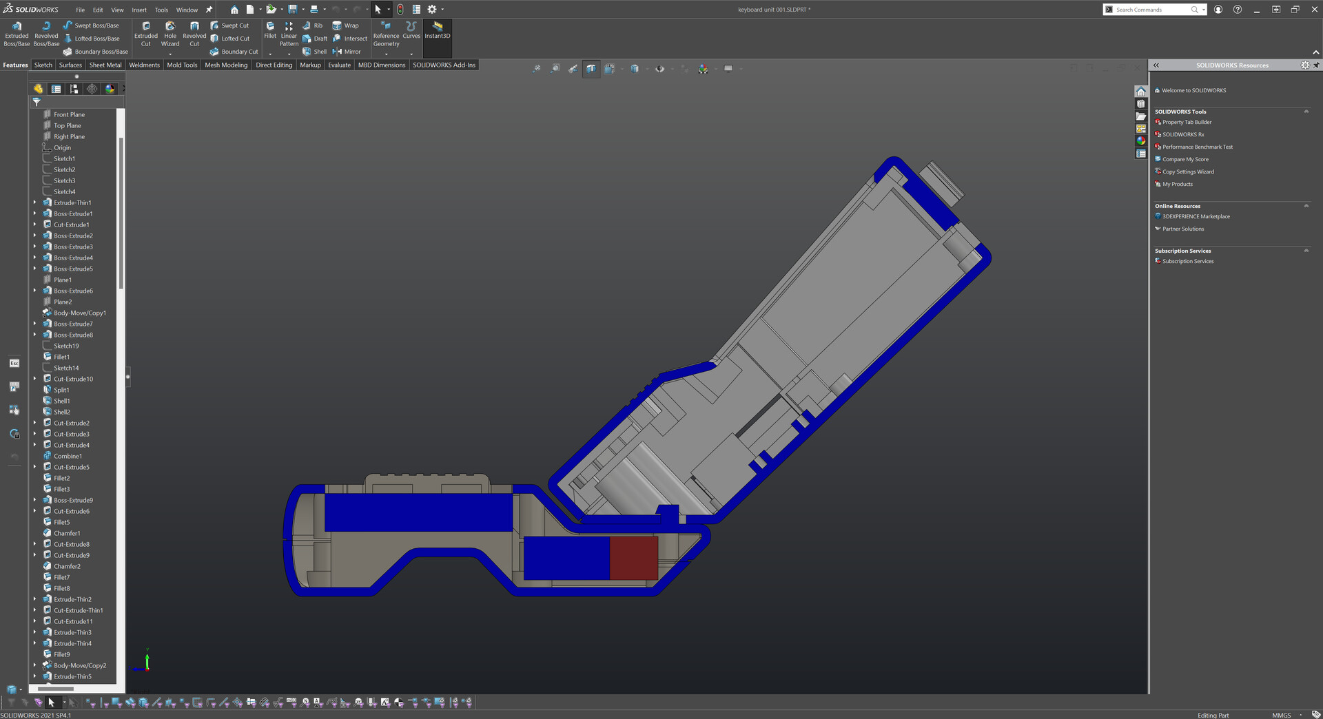
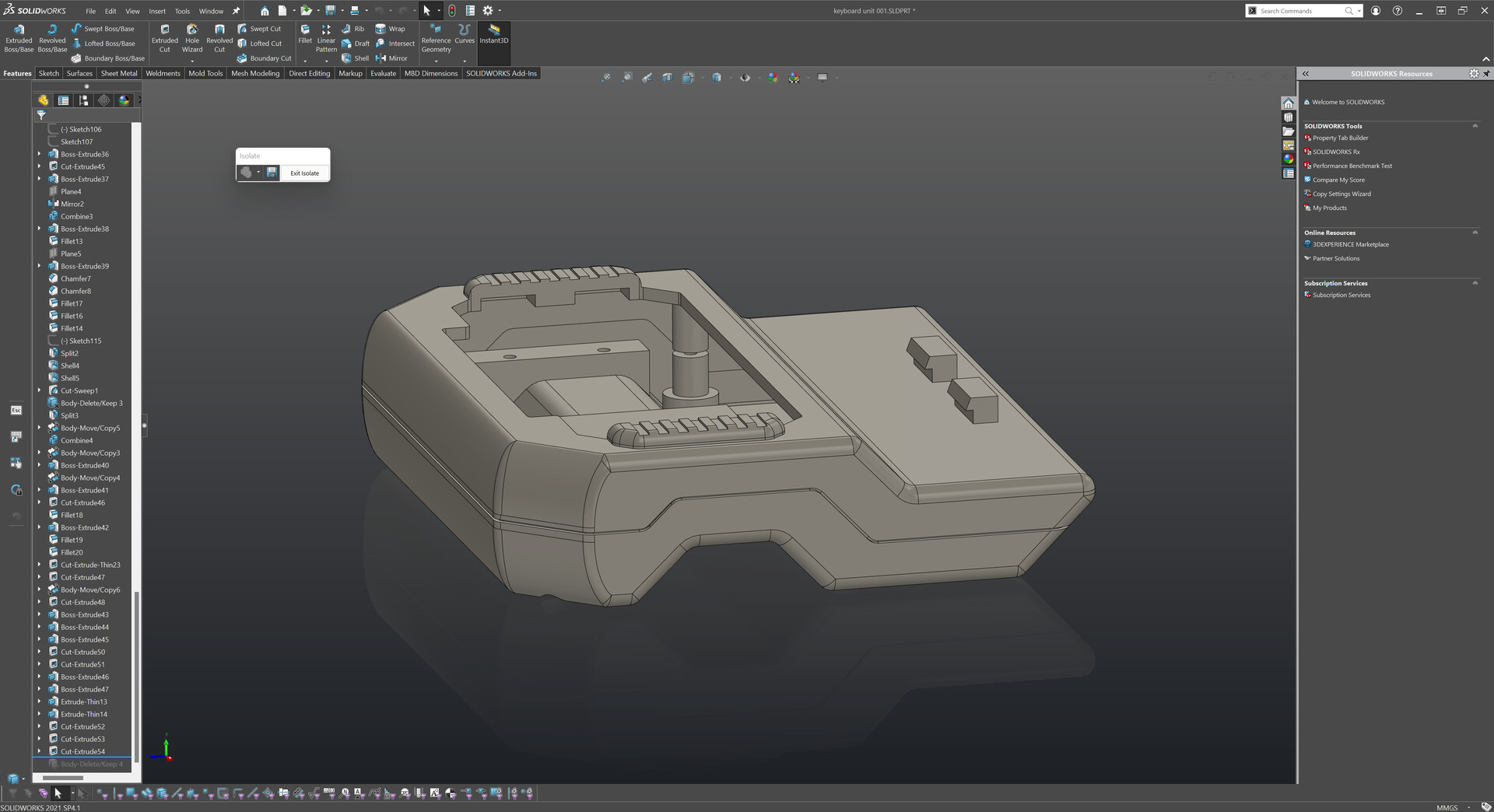
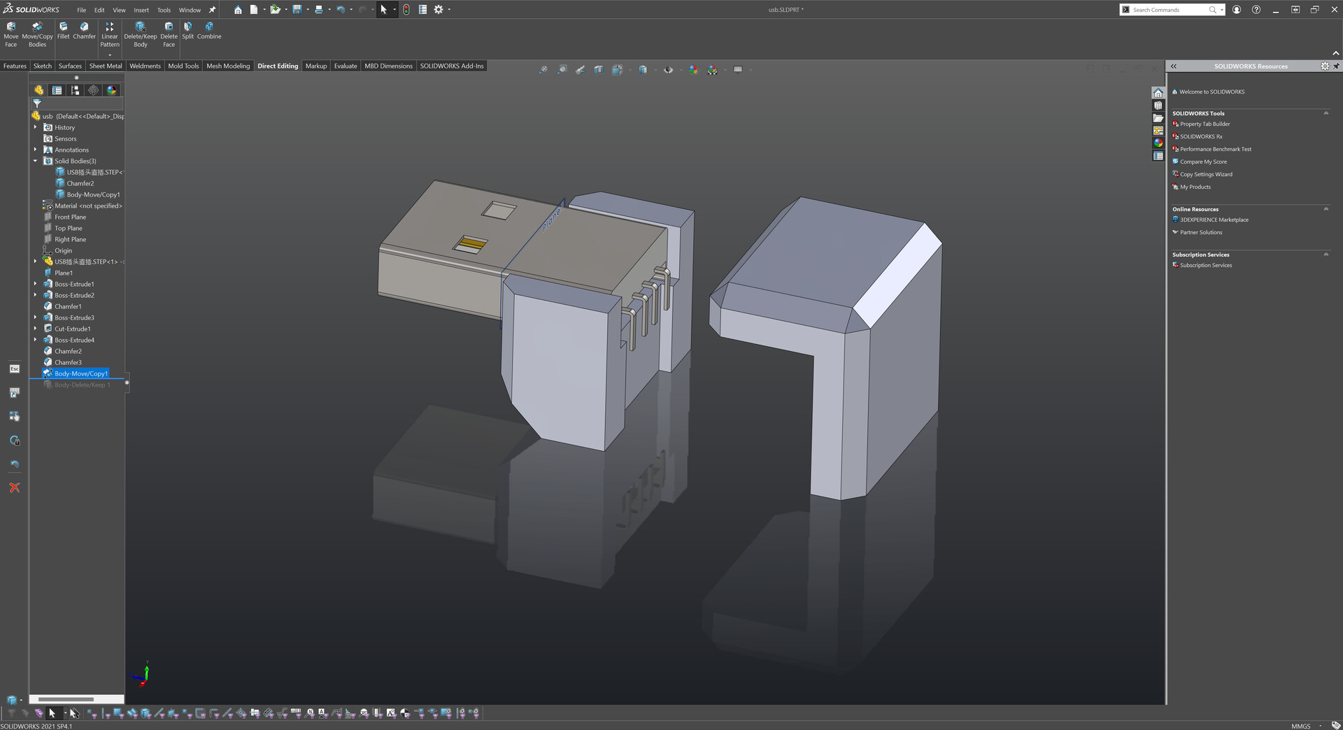
So first, I made a quick design on Solidworks.

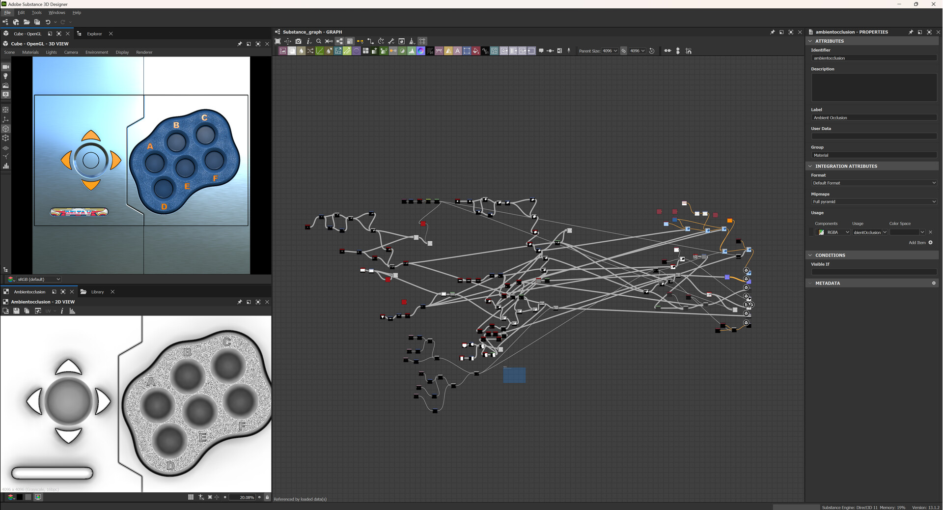
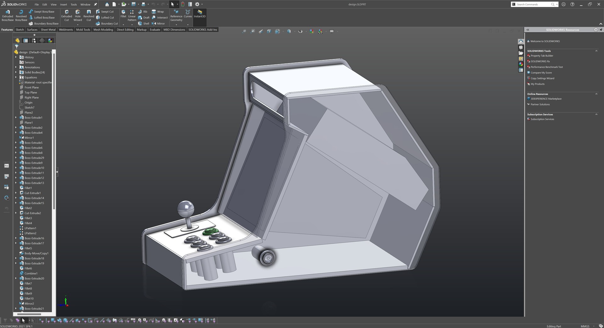
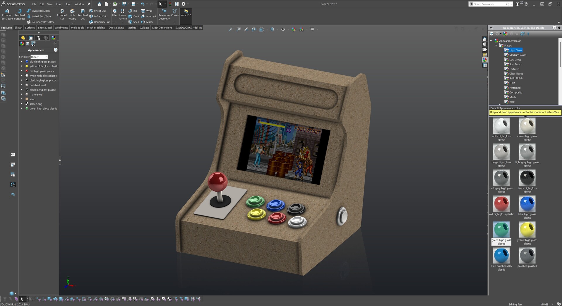
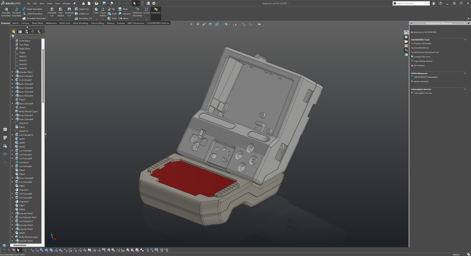
Made some coloring and texturing by the library.

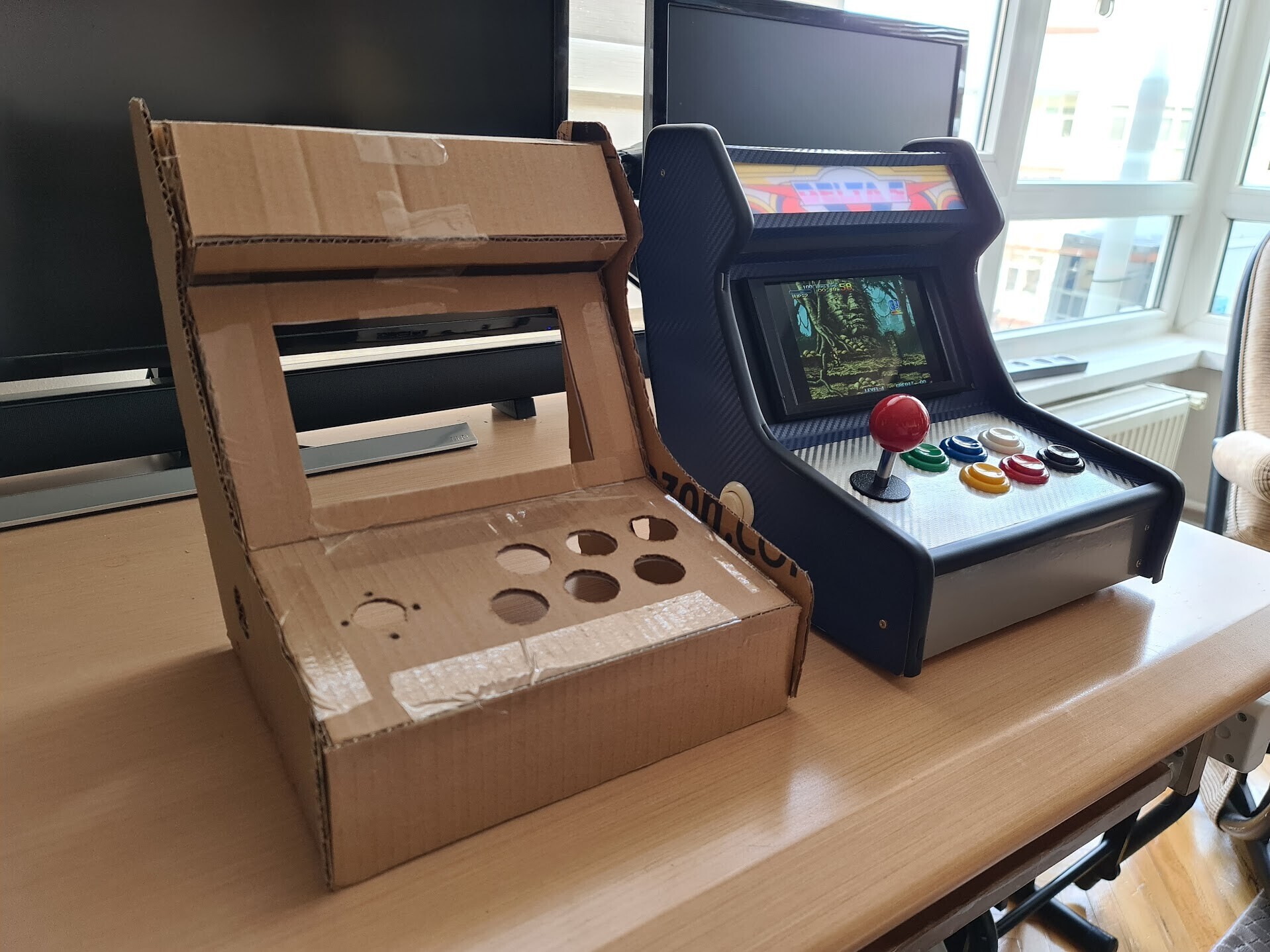
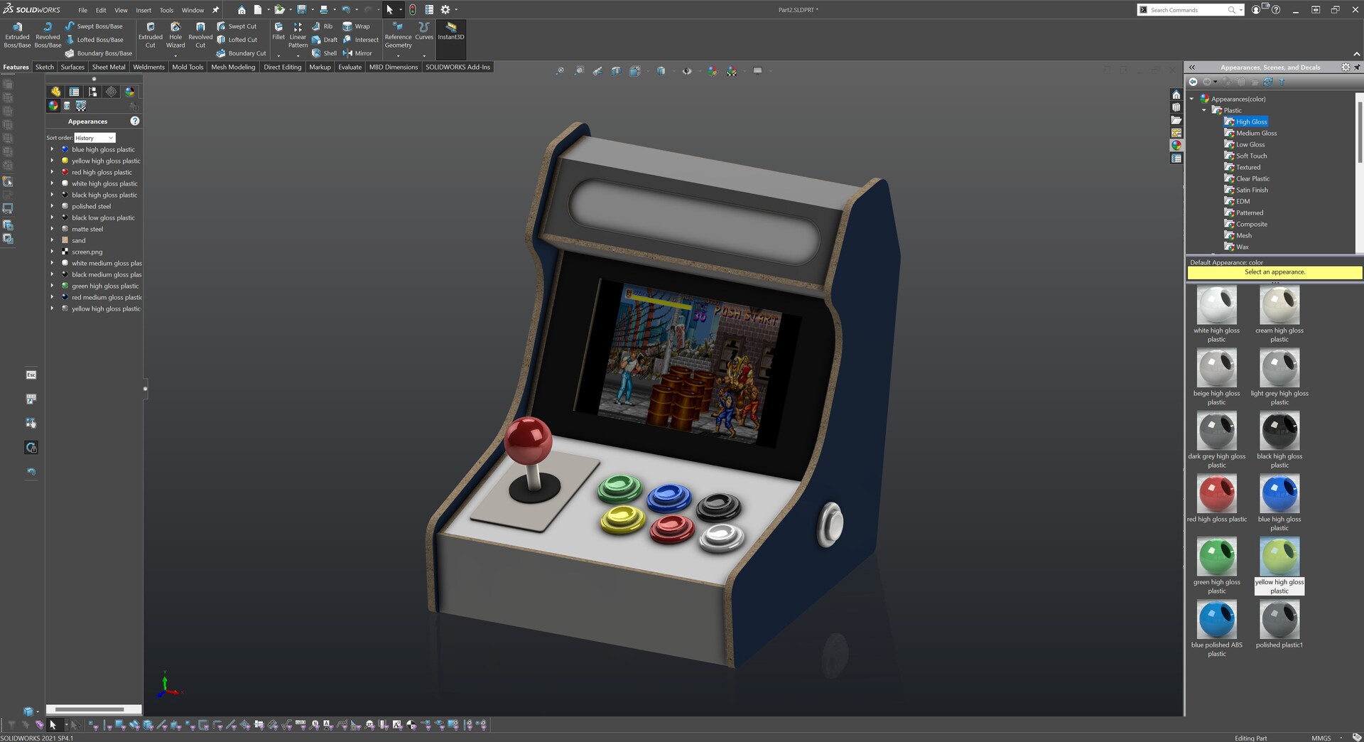
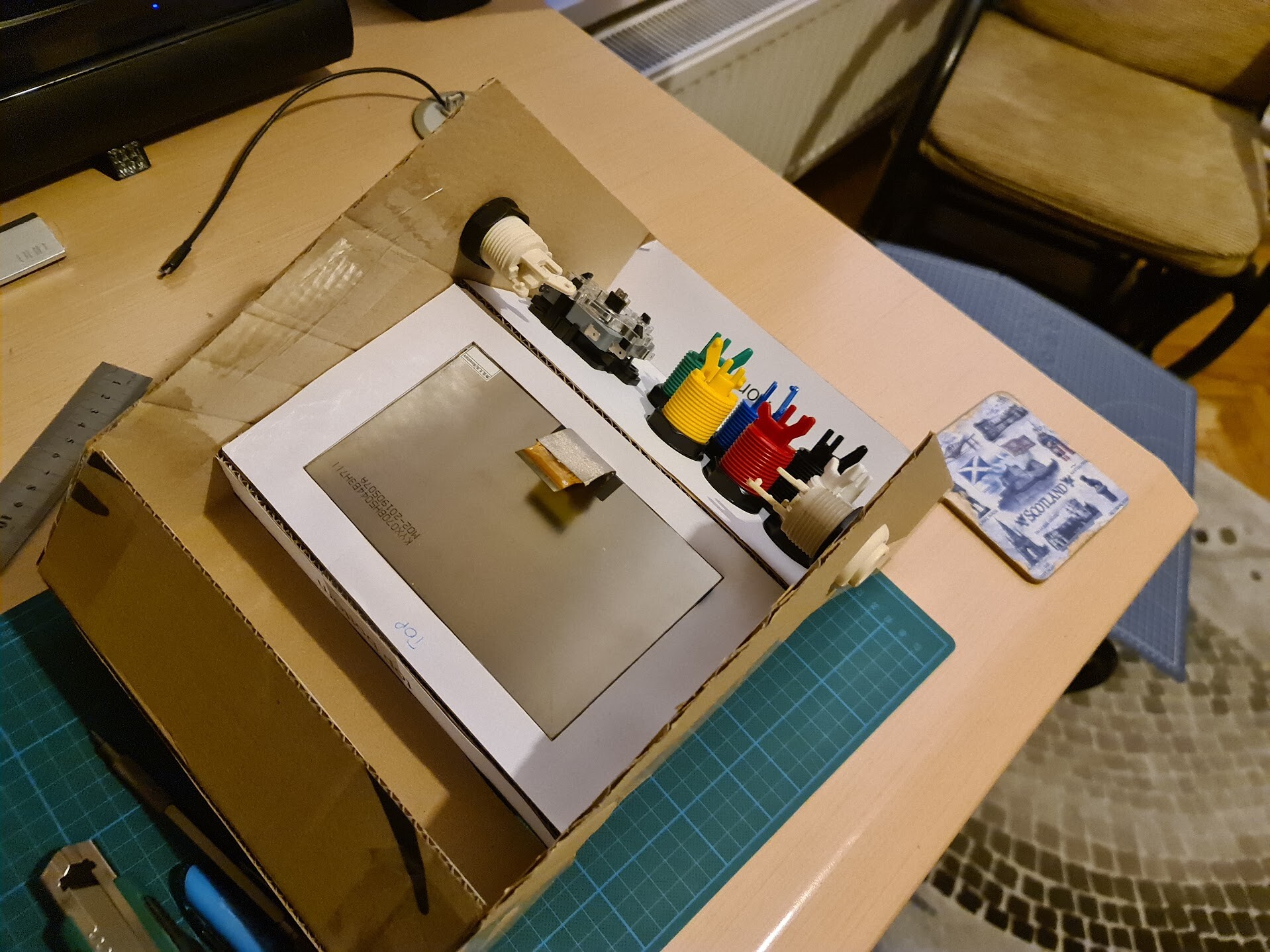
So with the screen size, form factor and the buttons and joystick I have at hand, I pretty satisfied with the result, so it was OK to continue making this real. But first I made a cardboard production. It's easier, less time consuming and low on cost to see how the thing will look like.

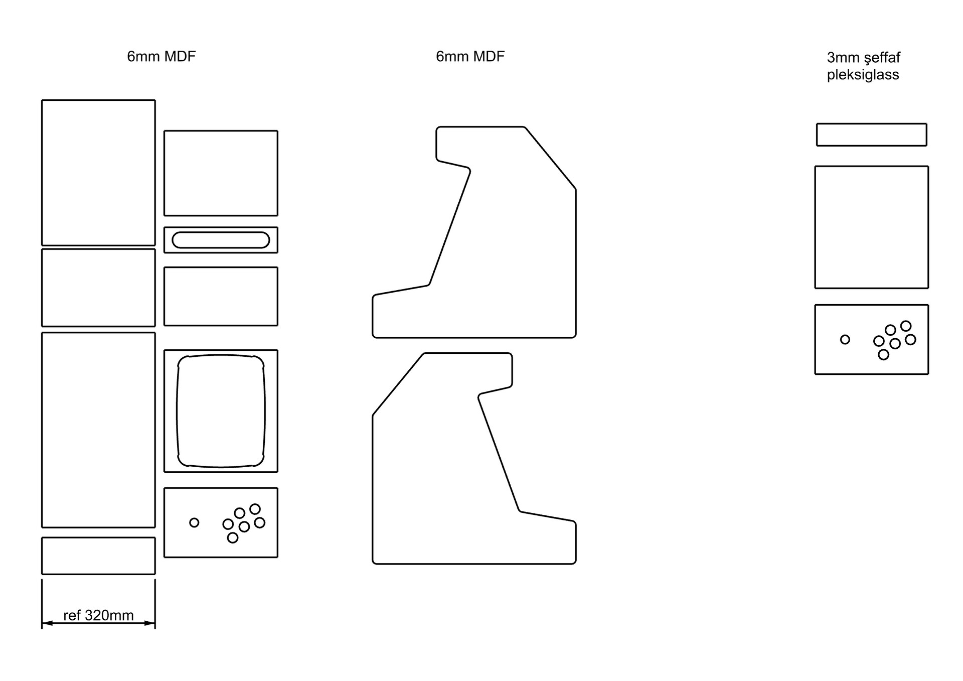
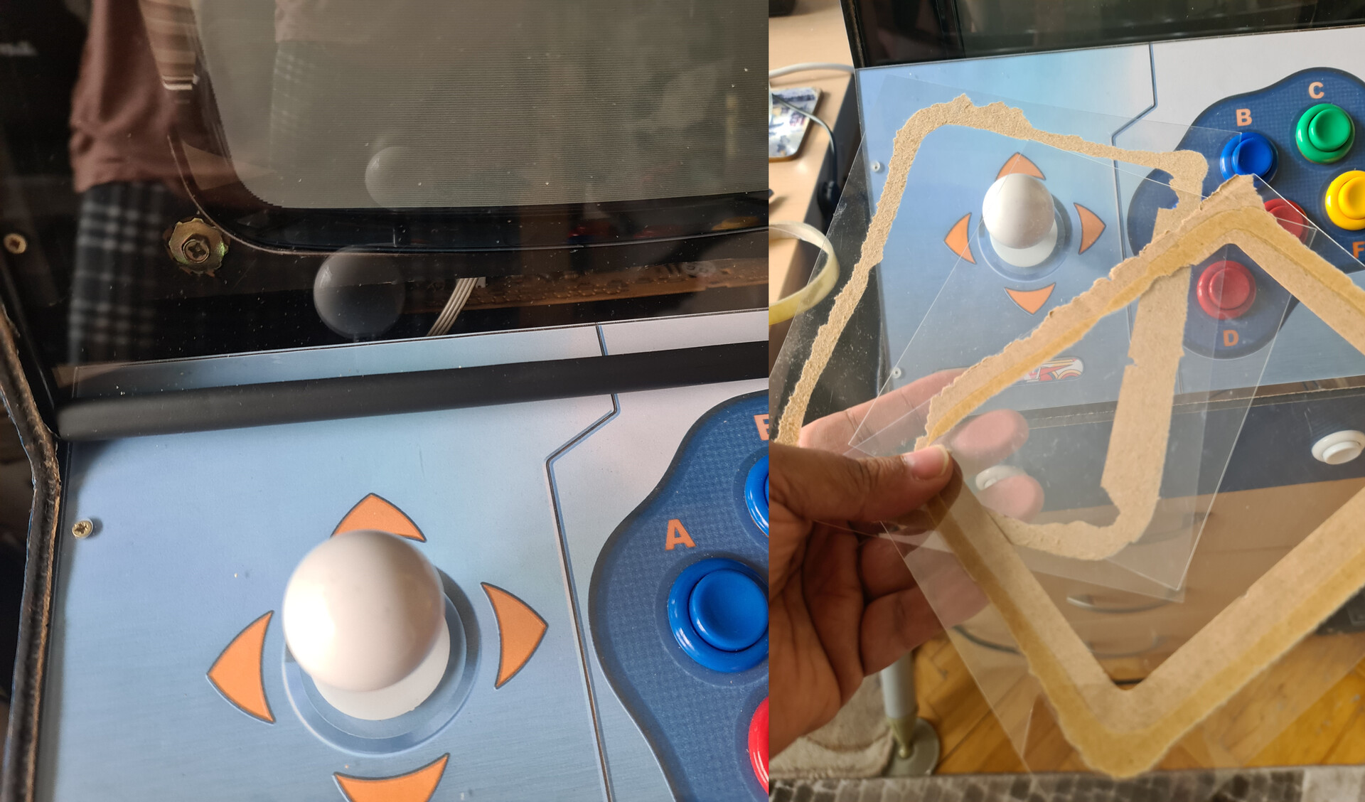
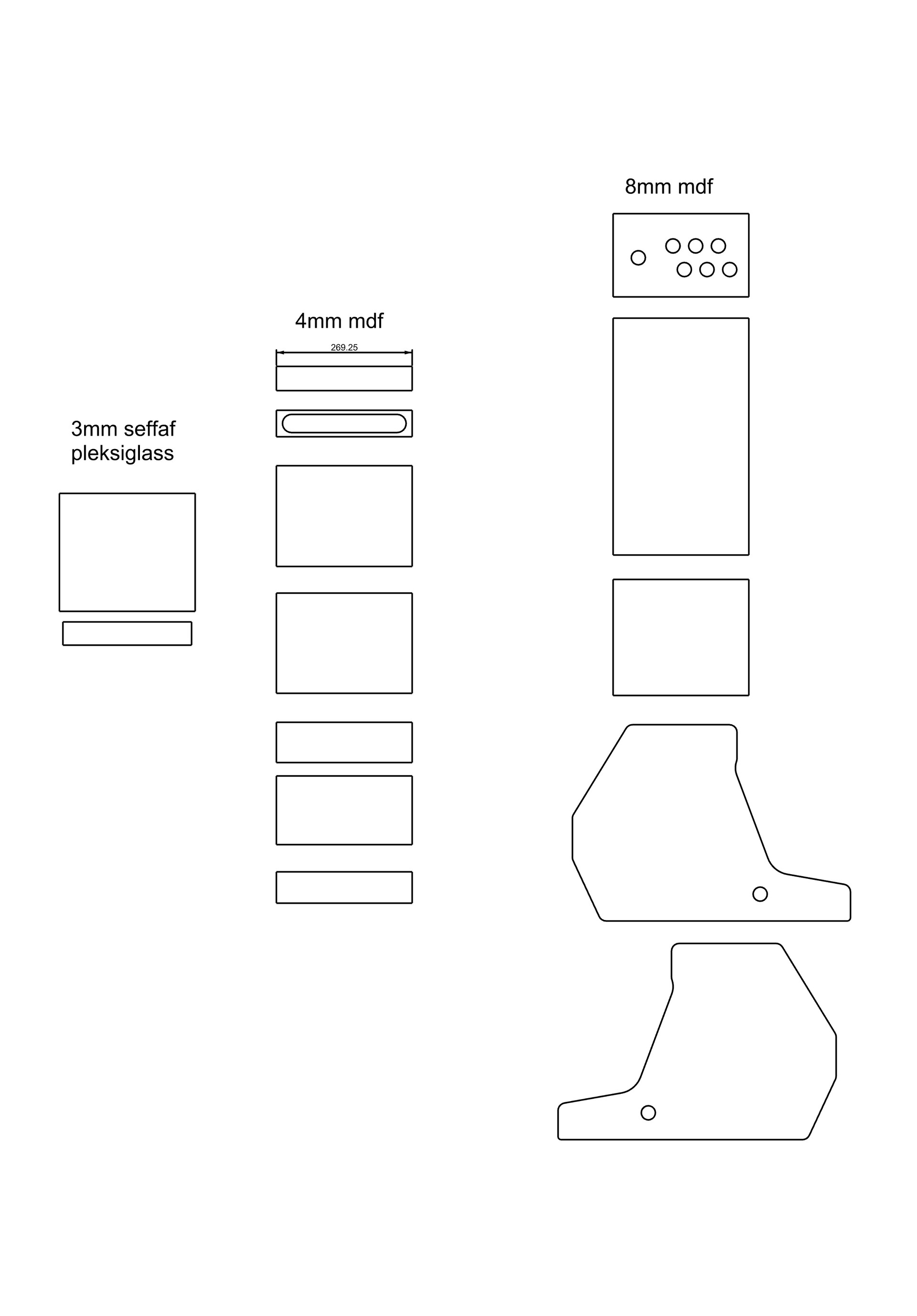
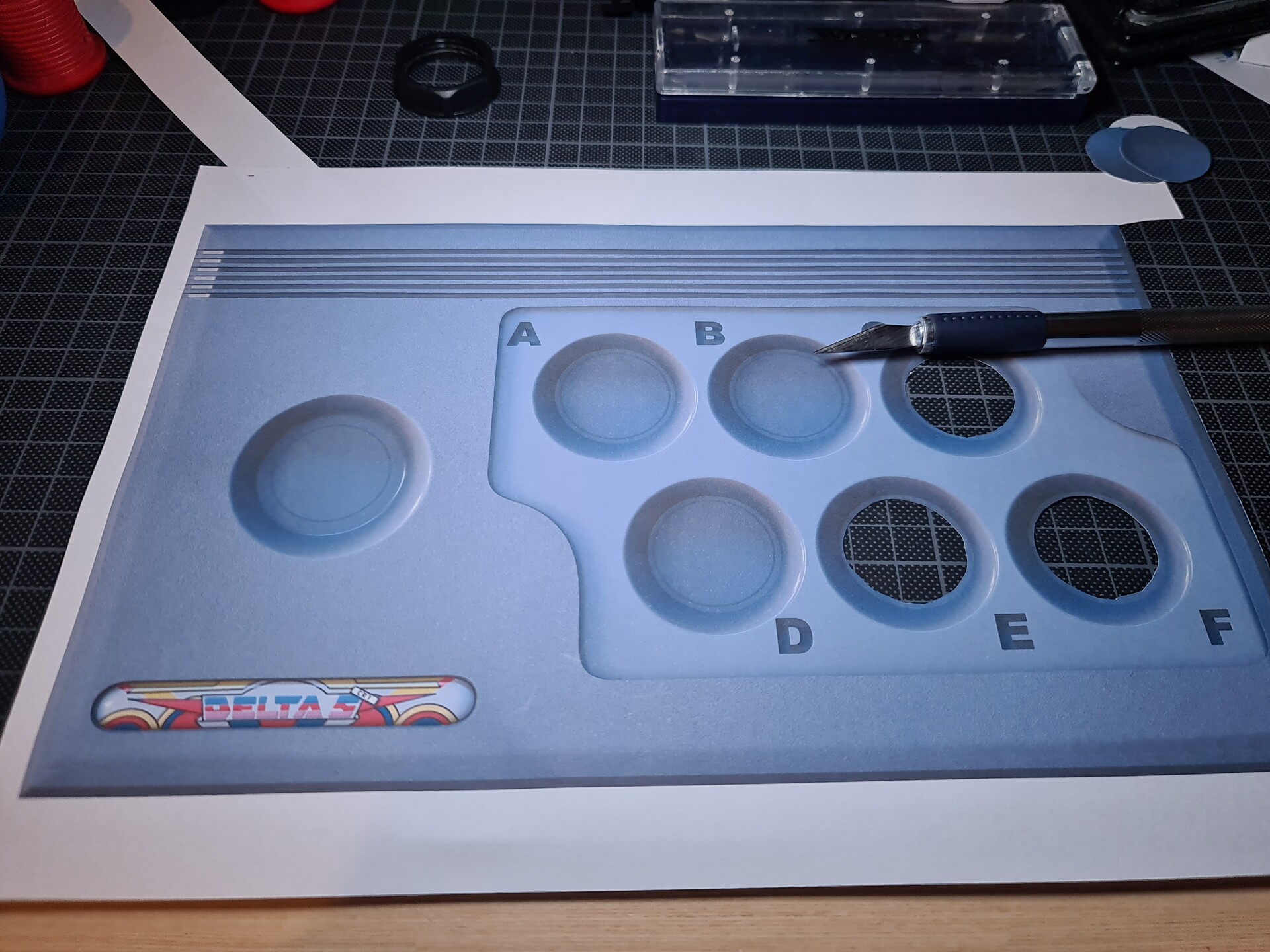
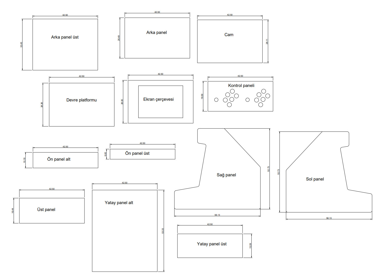
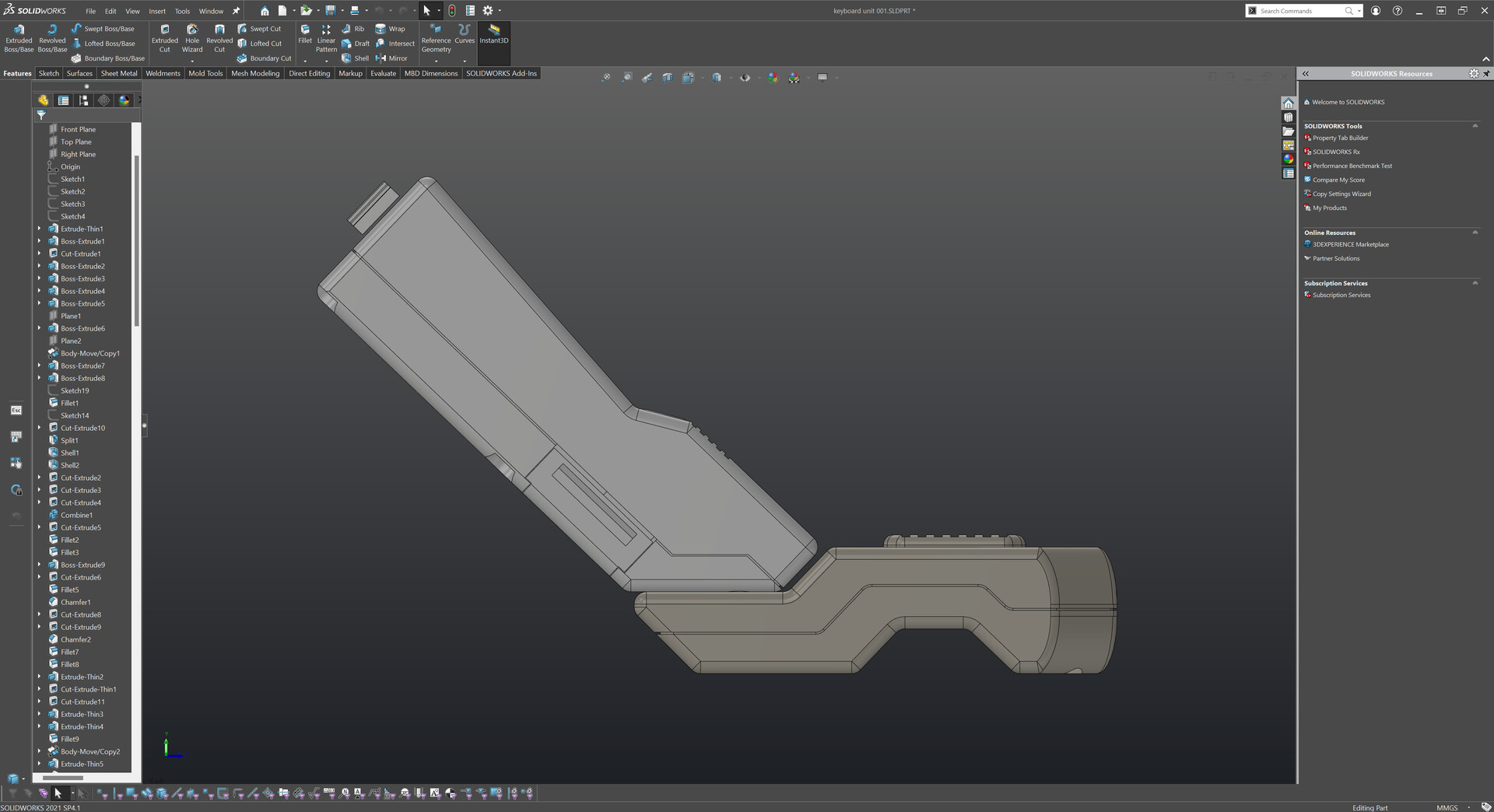
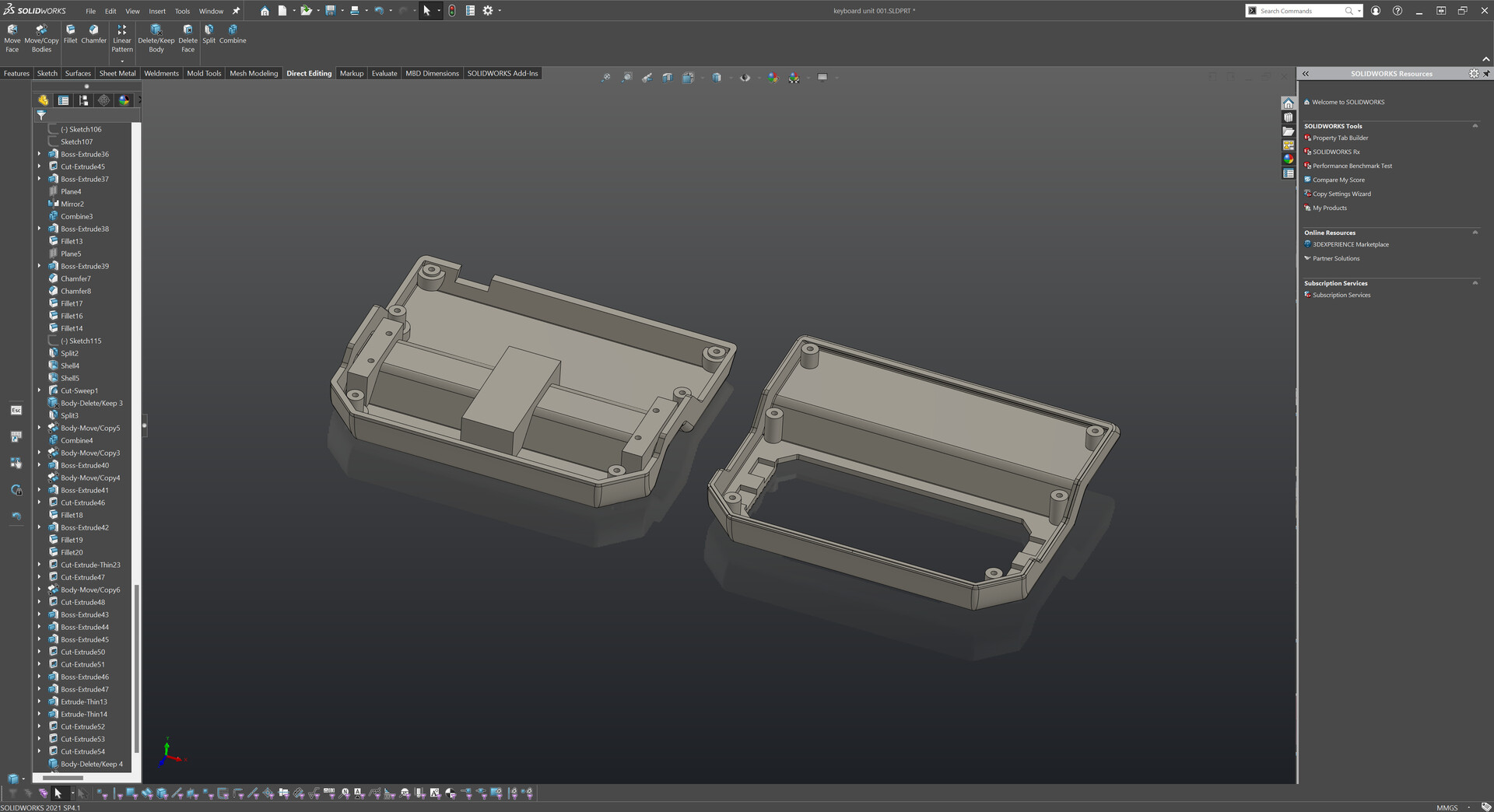
I extracted the surfaces from solidworks like this:

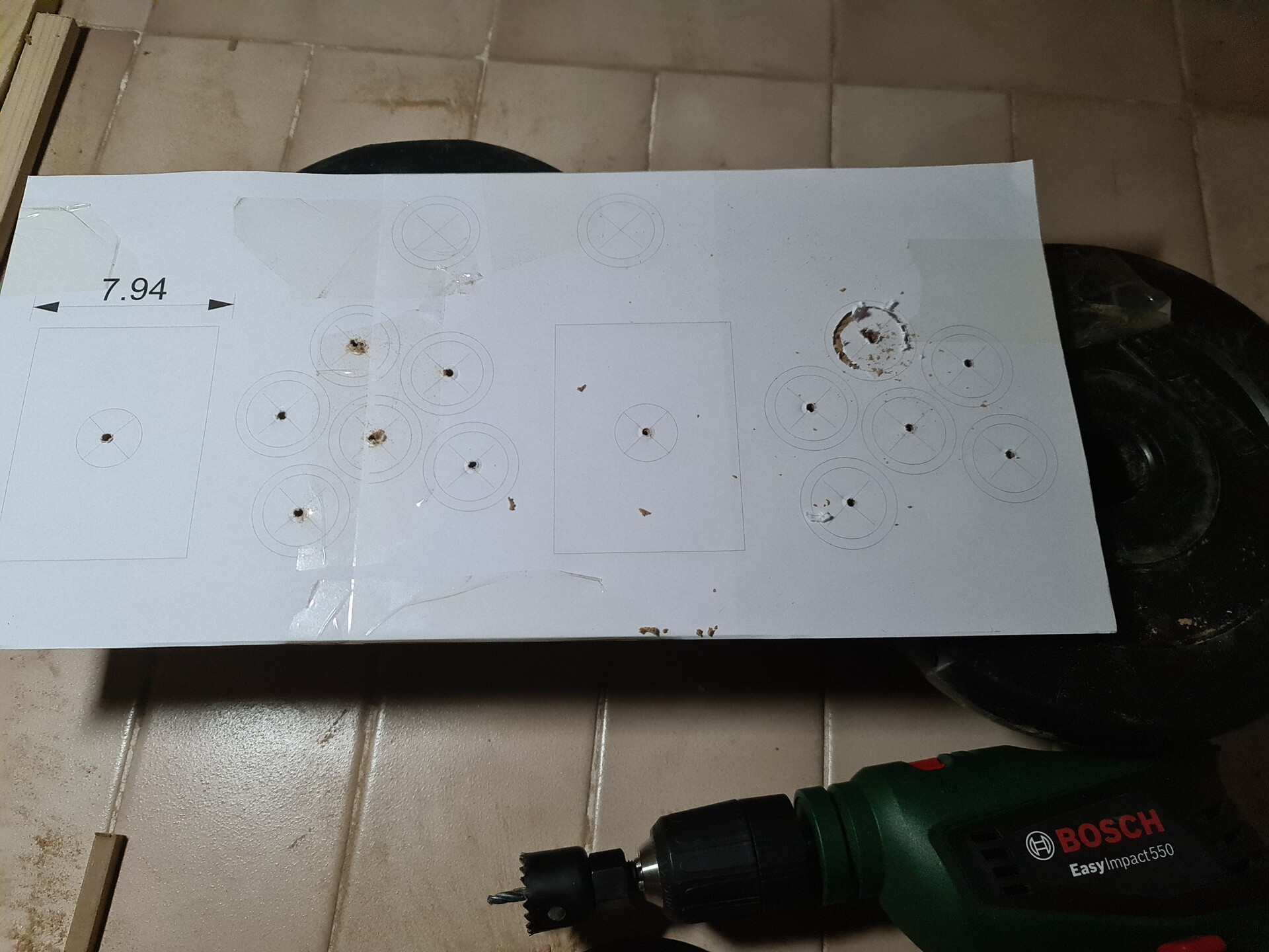
And printed these curves to use them as an overlay on cutting the cardboards. Regular printers are good devices that prints in a precise scale of your CAD software. So it2s the most important part that you had the correct scale of the production relative to your 3d model.  


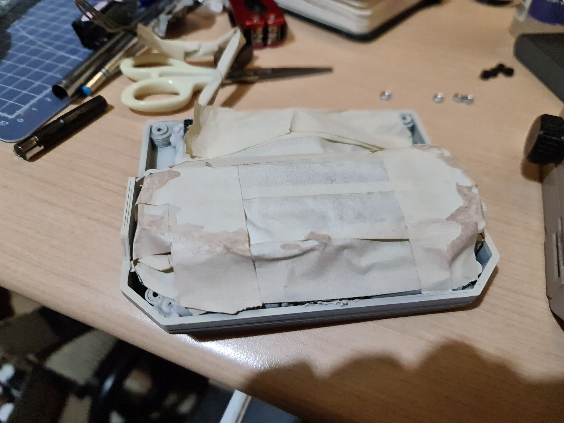
I easily managed to build the shape by packing tape.

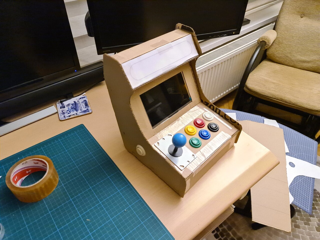
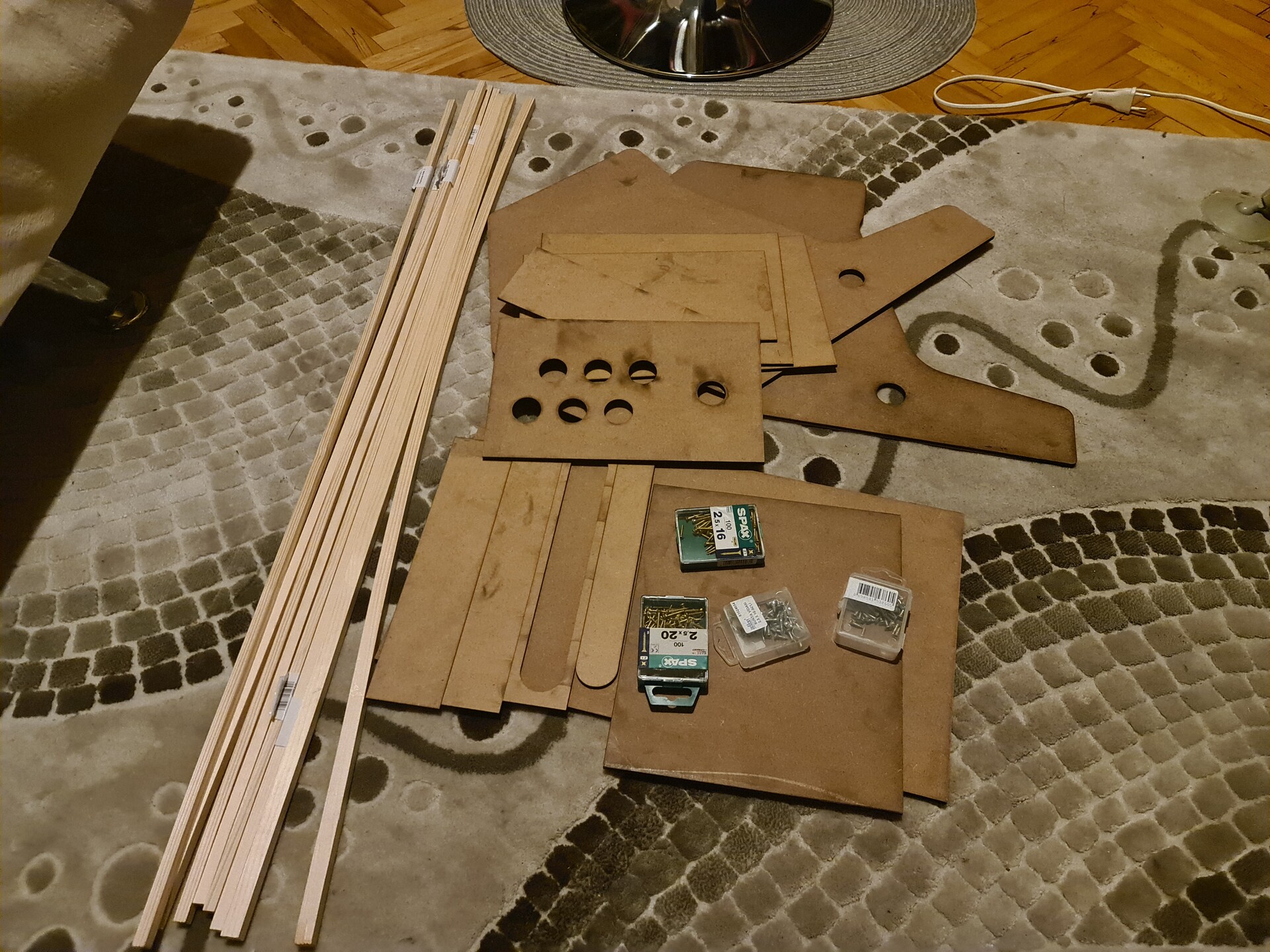
So the general size, and the components look allright, cosidering the inner parts to have enough clearance to put electronic components as well. With that confirmed, I went for shopping some Plywood, MDF etc.

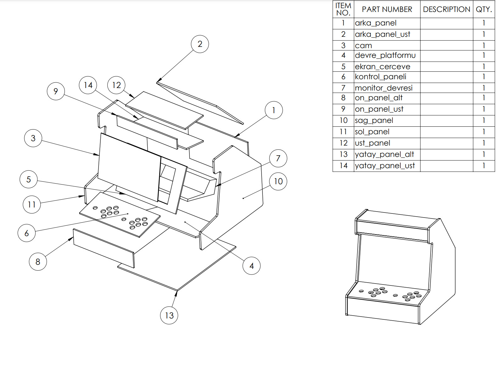
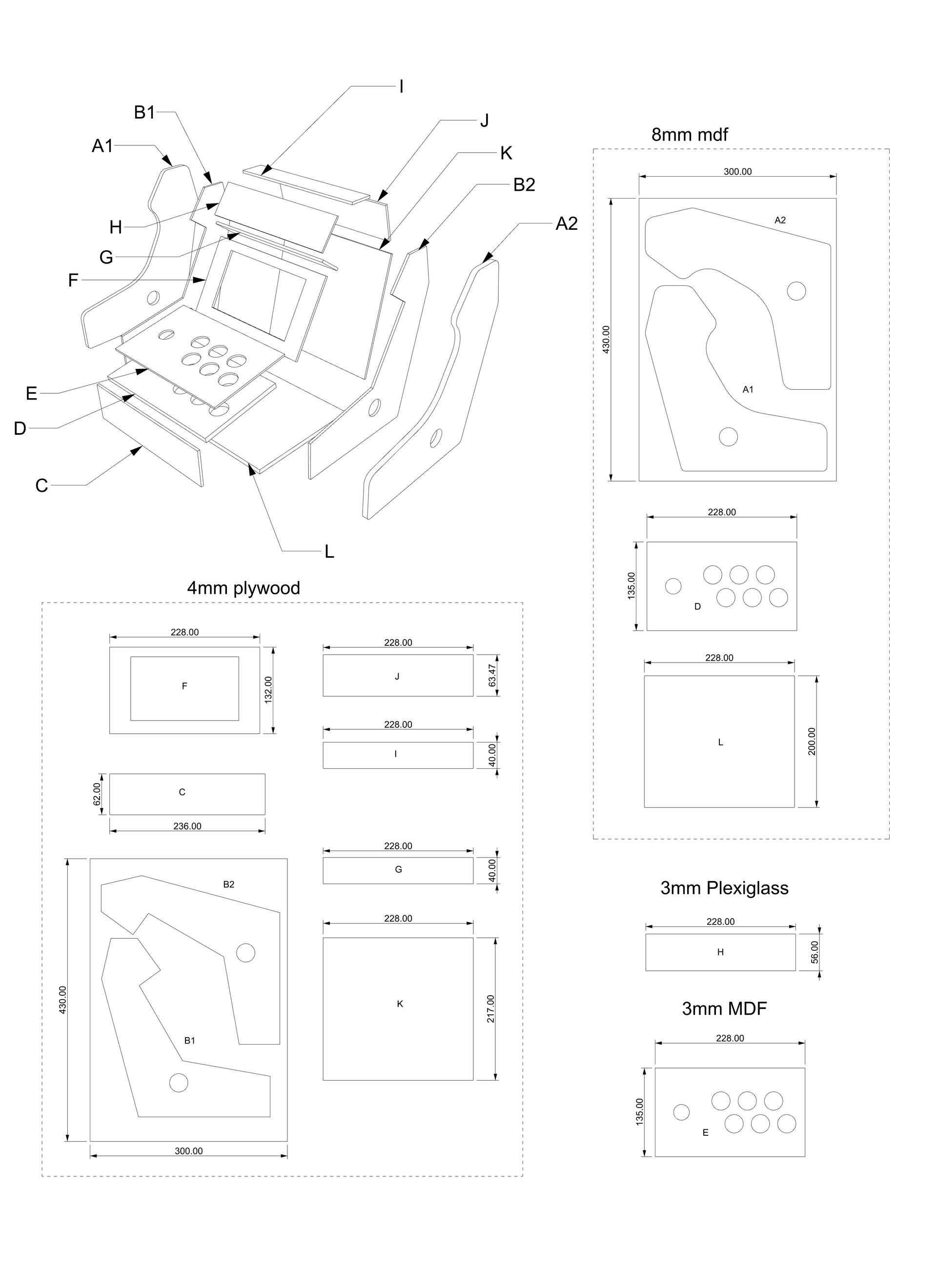
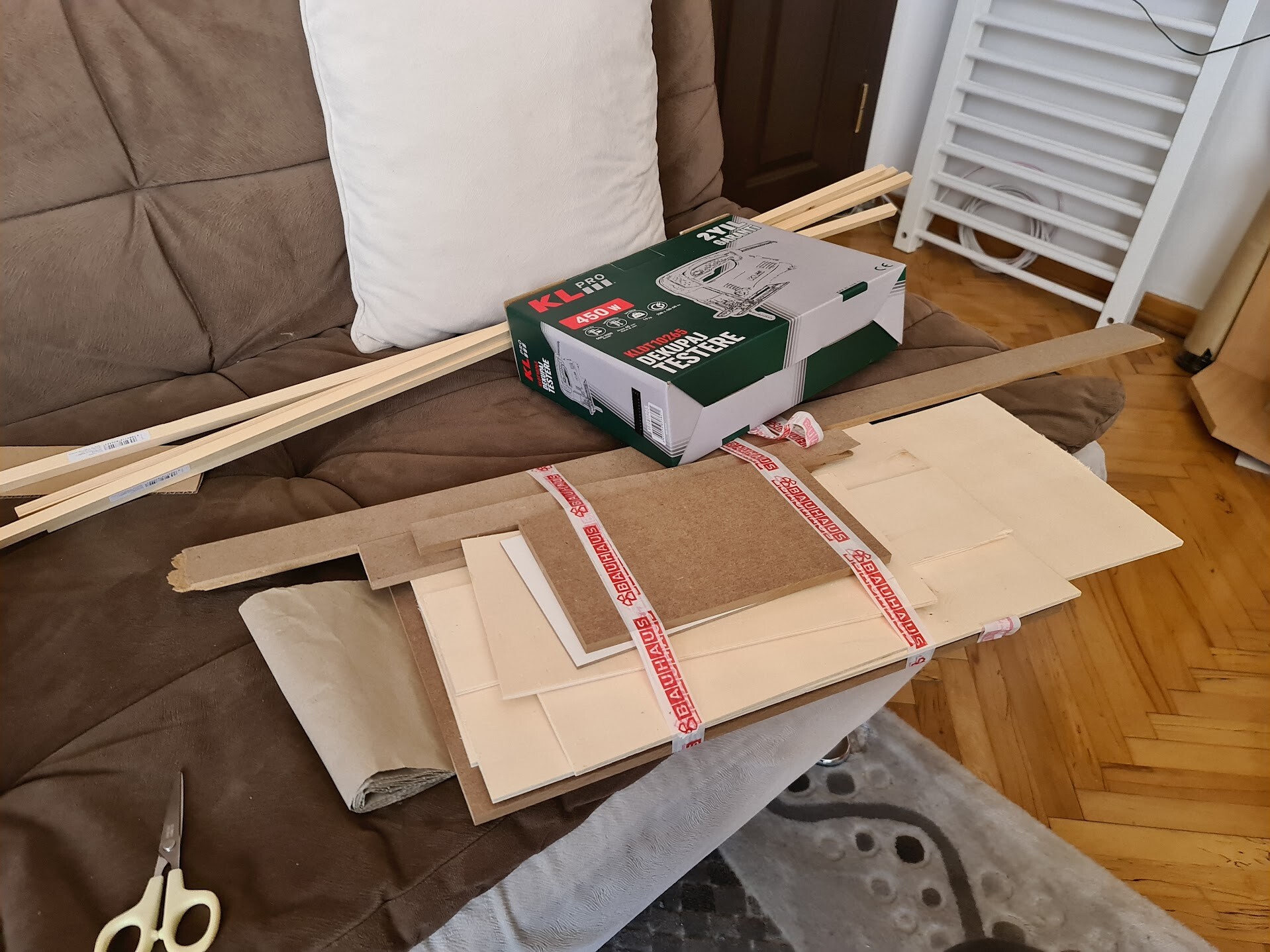
I bought 4mm Plywood (lighter wood), 8mm MDF (darker one), 3mm MDF (with white layer coated). This is the bill of materials. PDF version can be downloaded by this link (if you're going to use, don't forget to check the dimensions and scaling):
https://drive.google.com/file/d/11J50BwOvIOB7_zke6LjI_HYhrdQiZcWt/view?usp=sharing

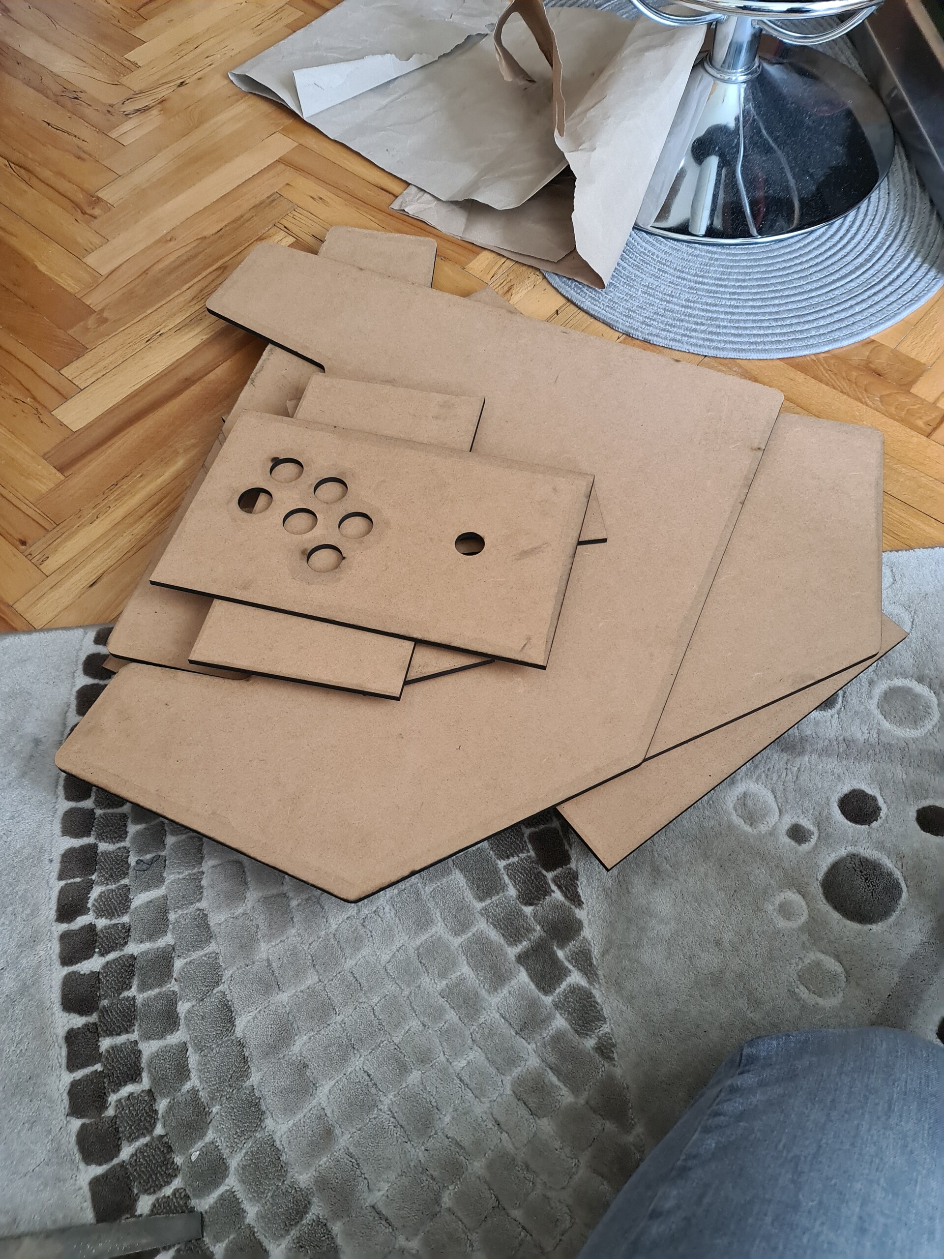
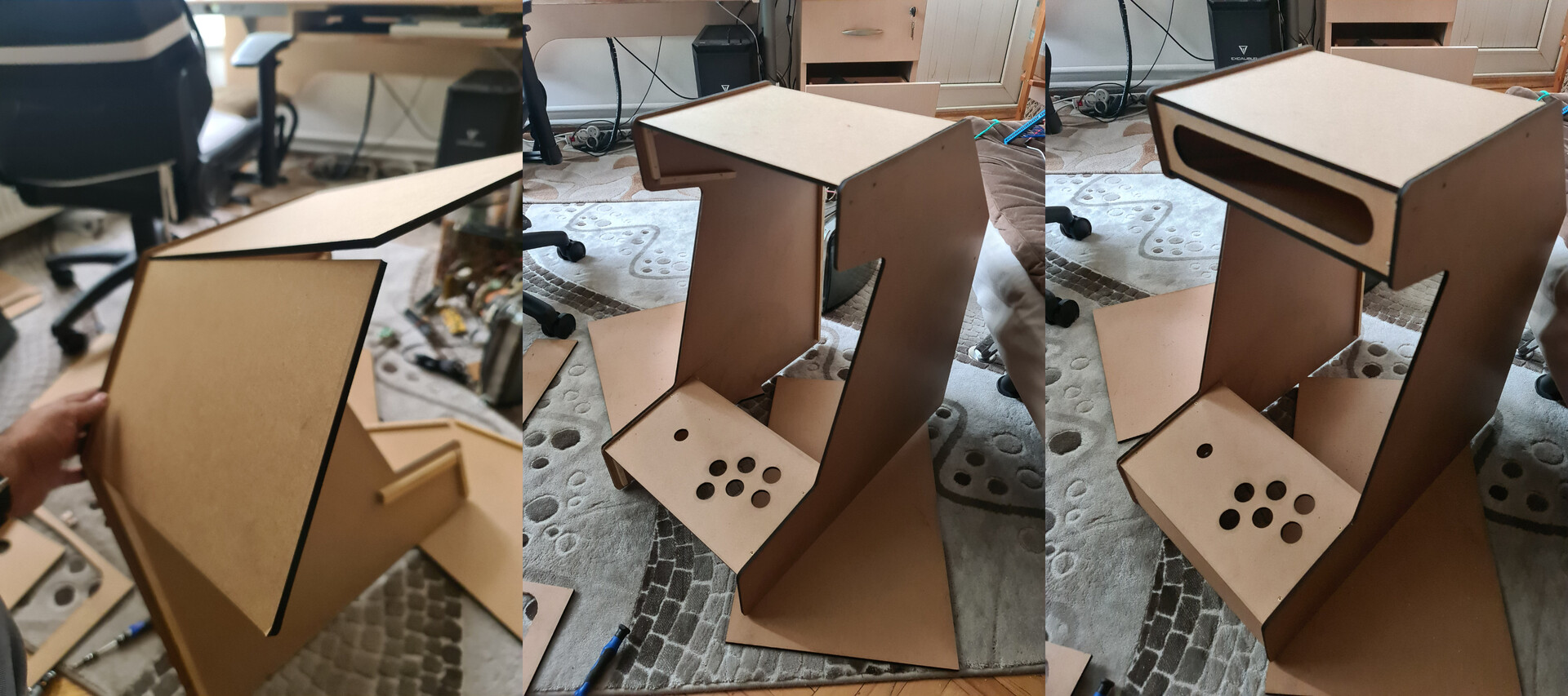
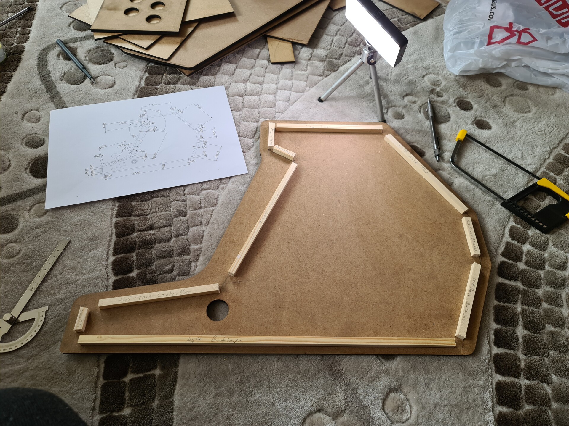
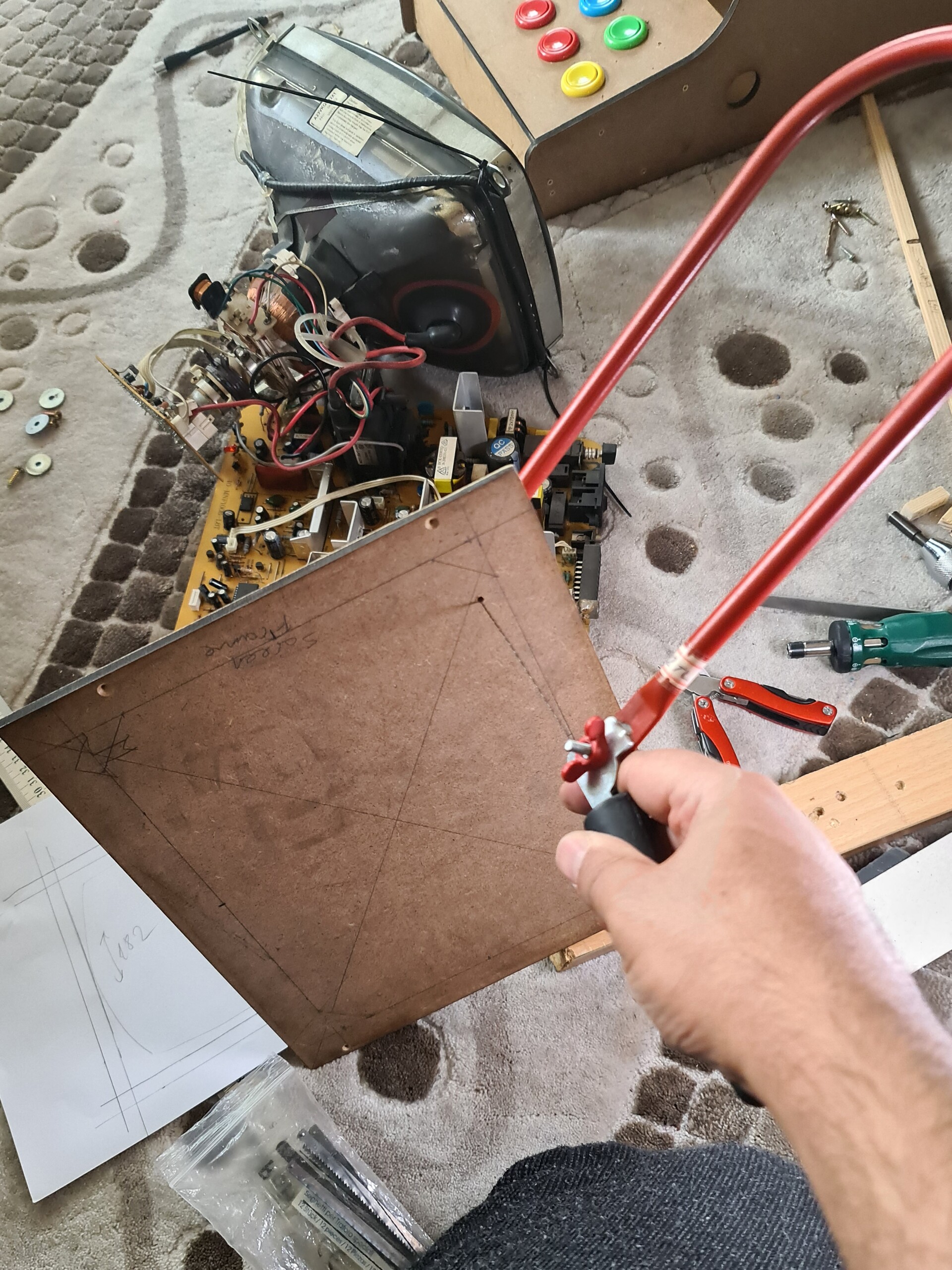
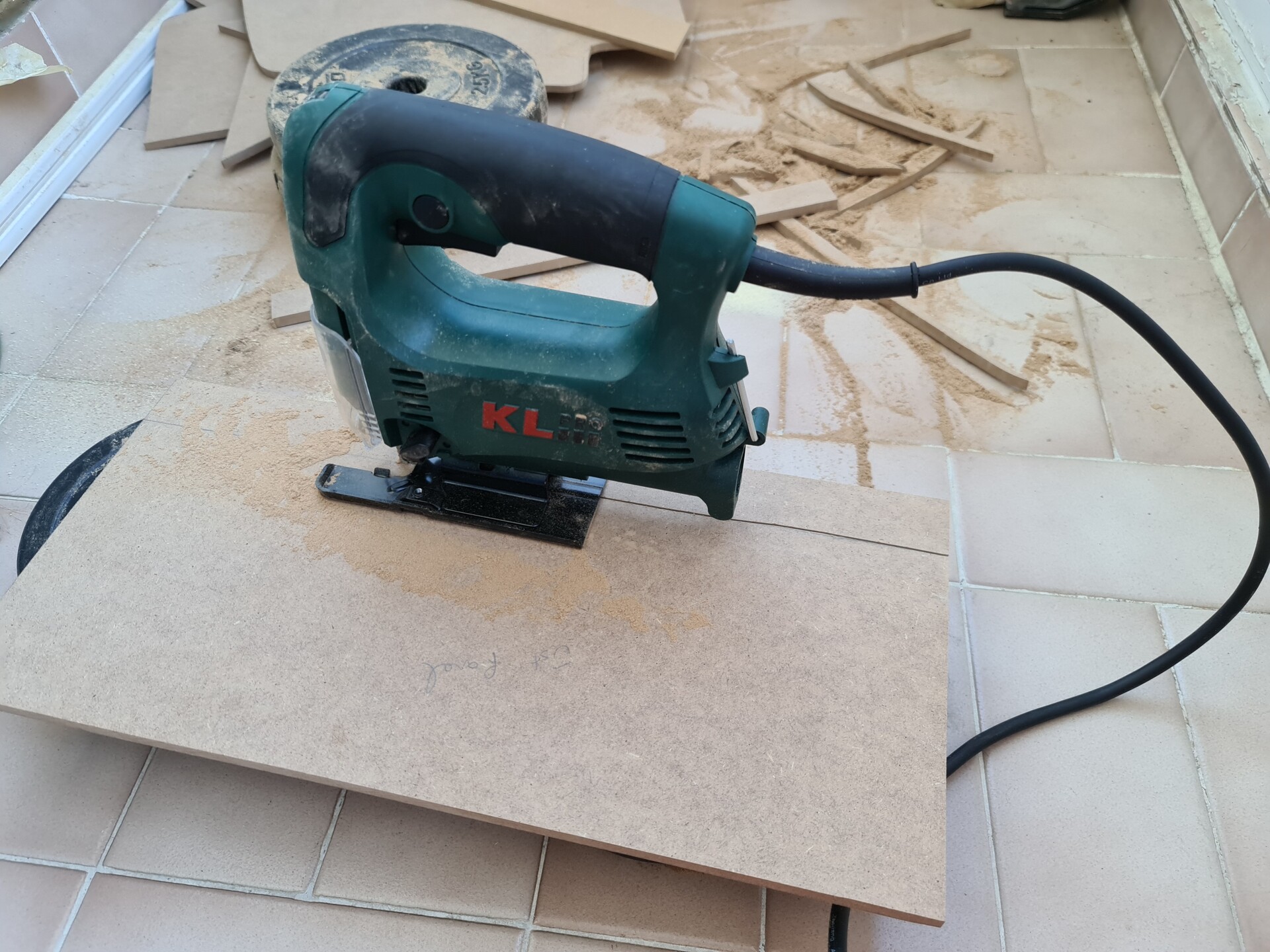
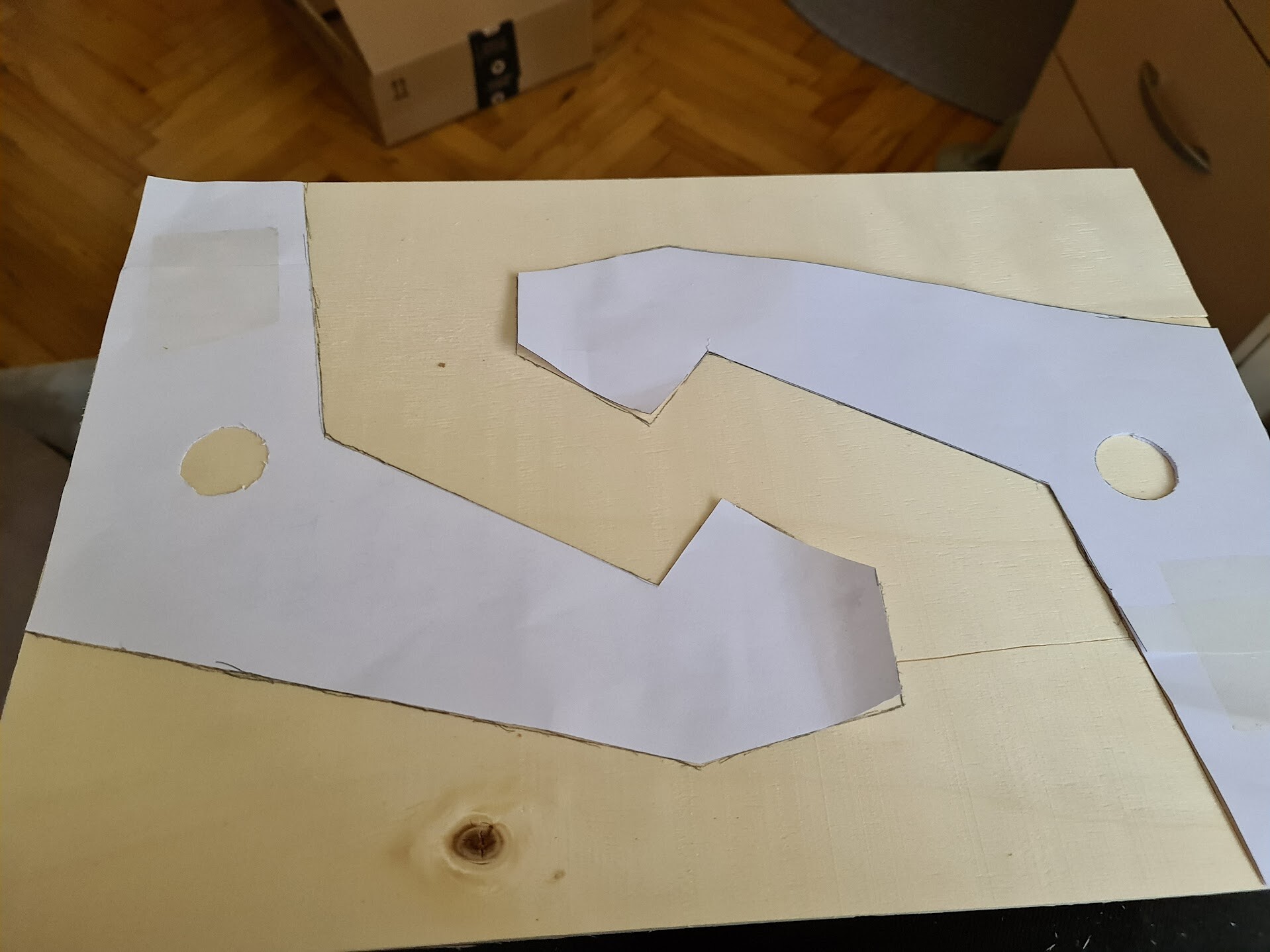
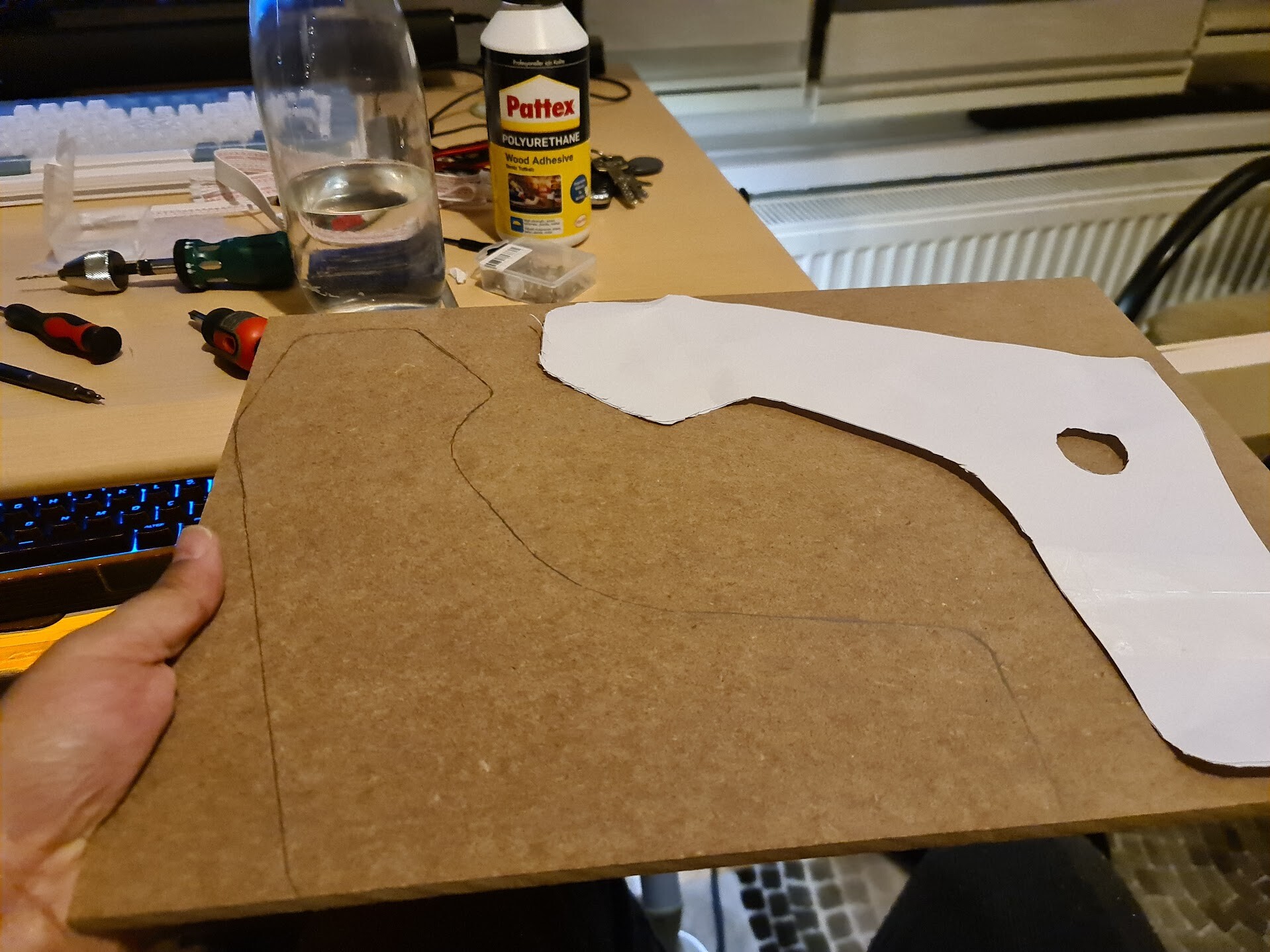
First I put the templates that I printed with a regular printer over the wooden boards and draw the boarders around the templates. Then I started cutting with fretsaw.

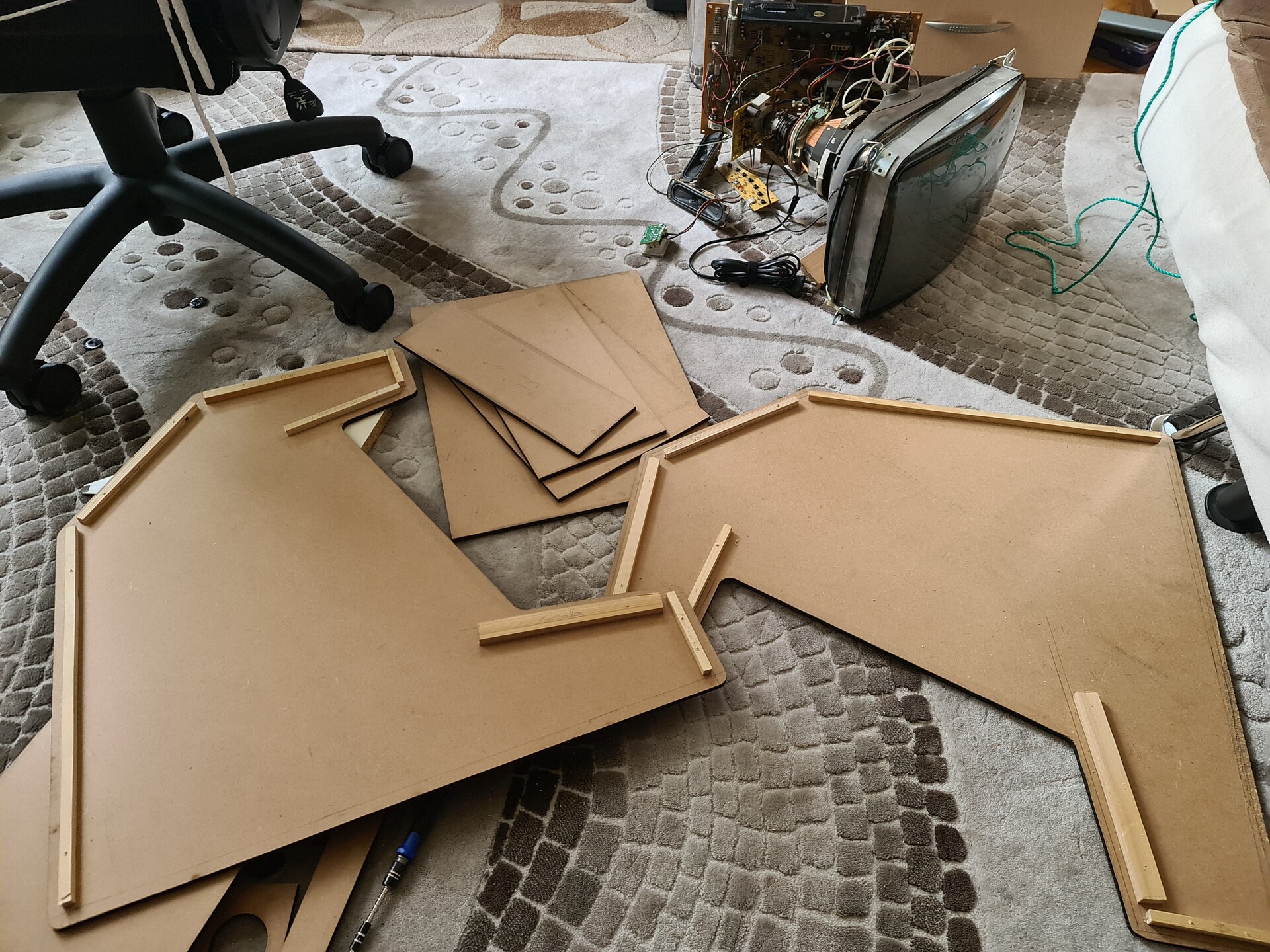
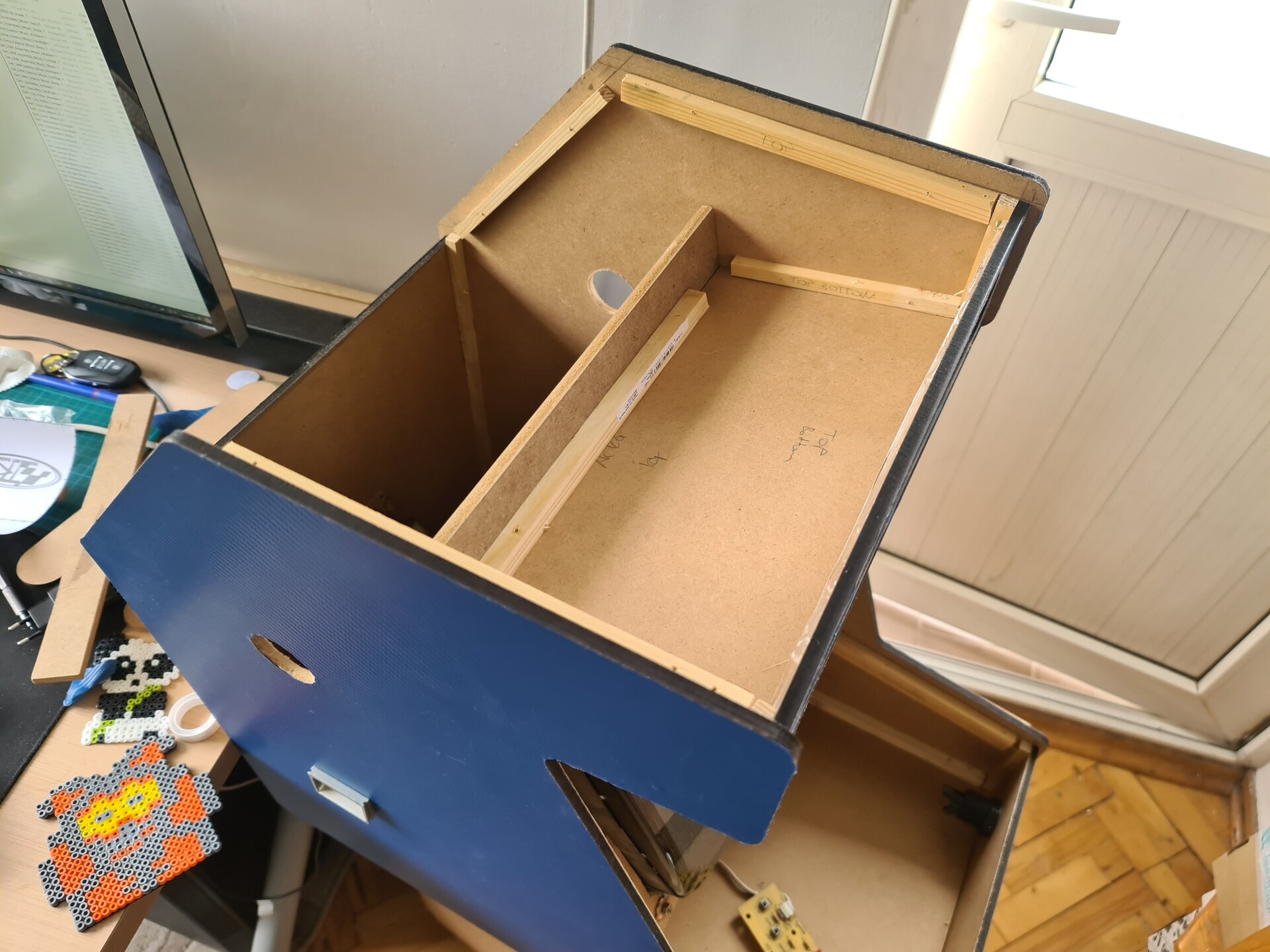
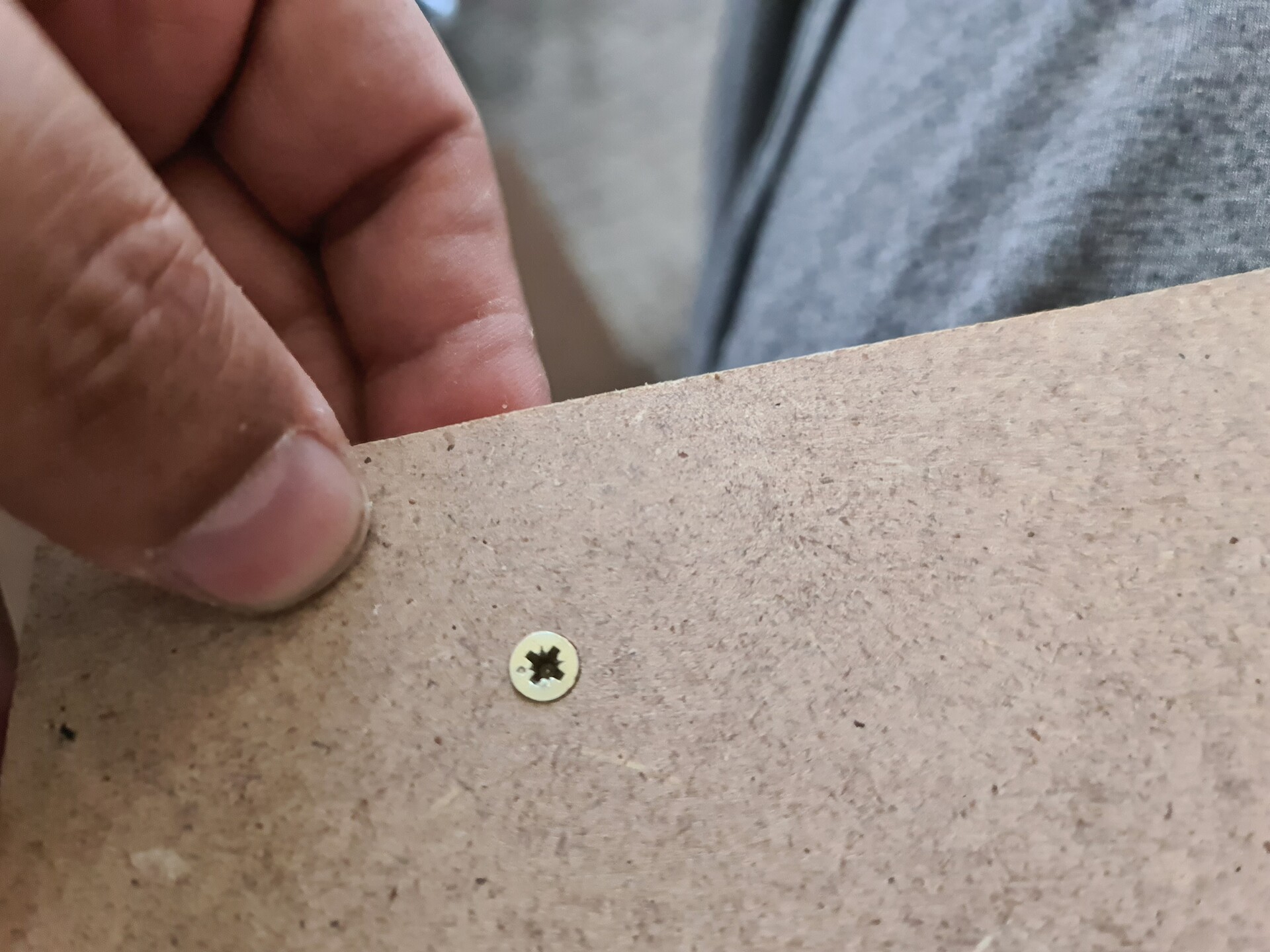
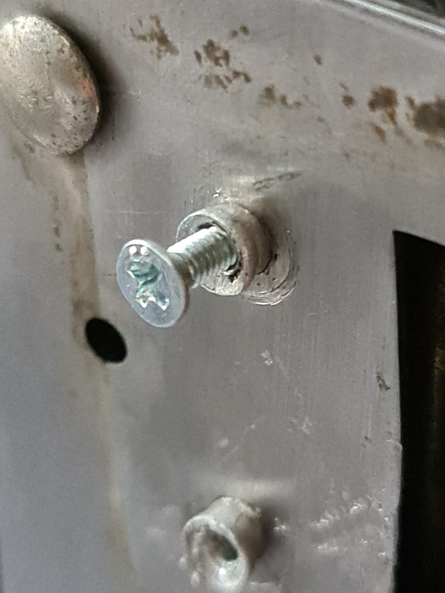
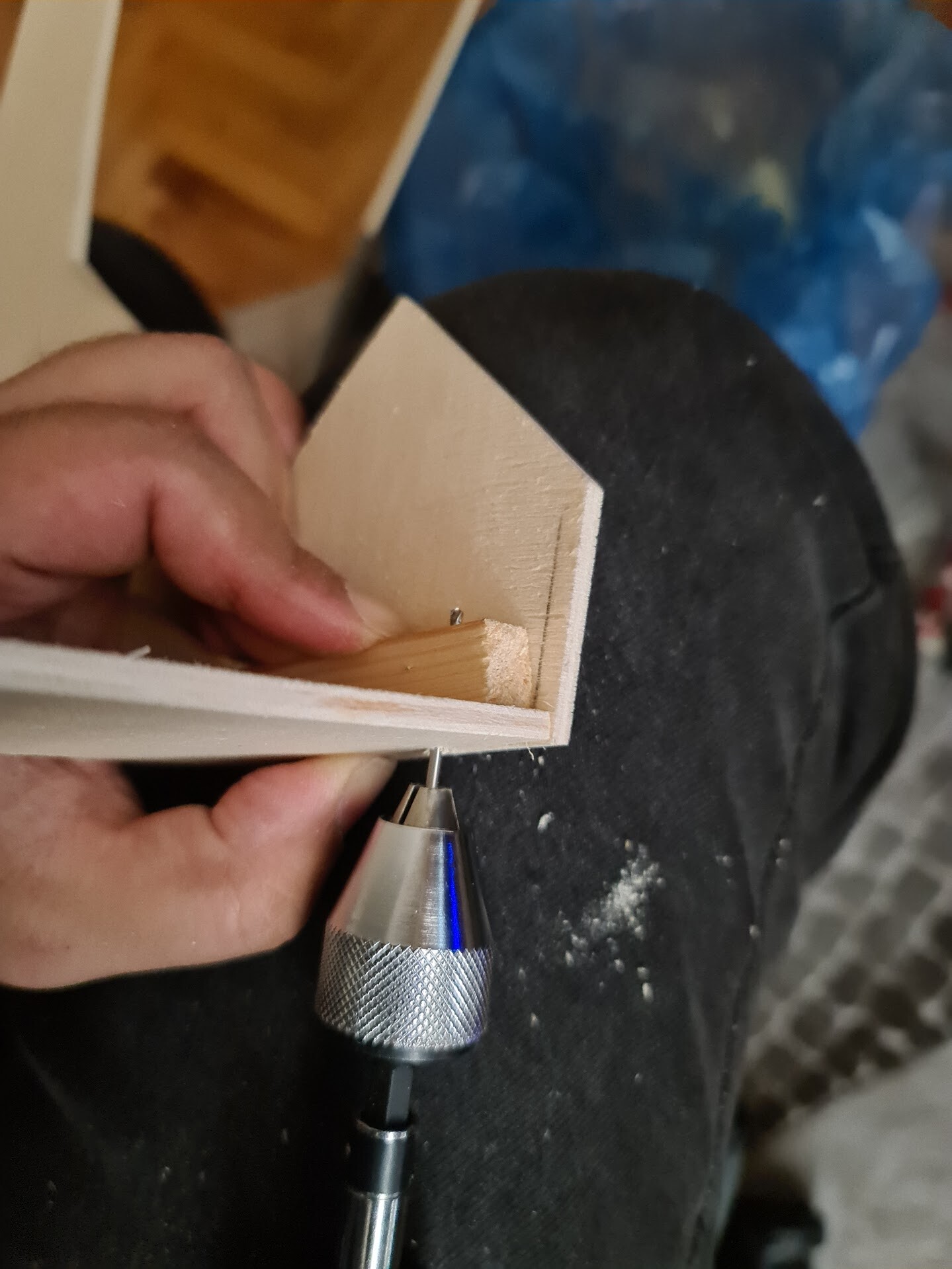
I used wooden sticks to connect perpendicular boards together. I used self tapping screws to connect the sticks with the boards.

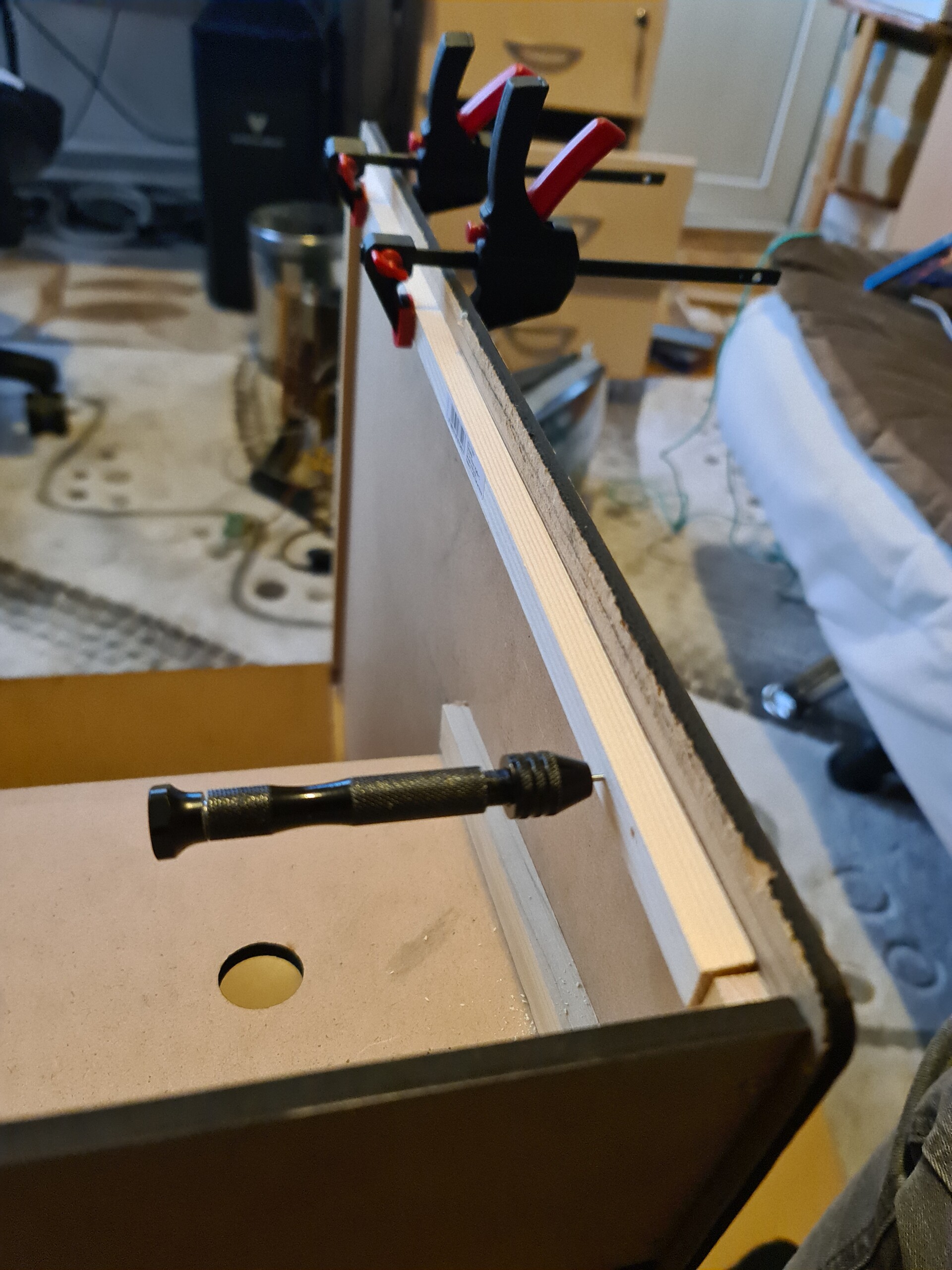
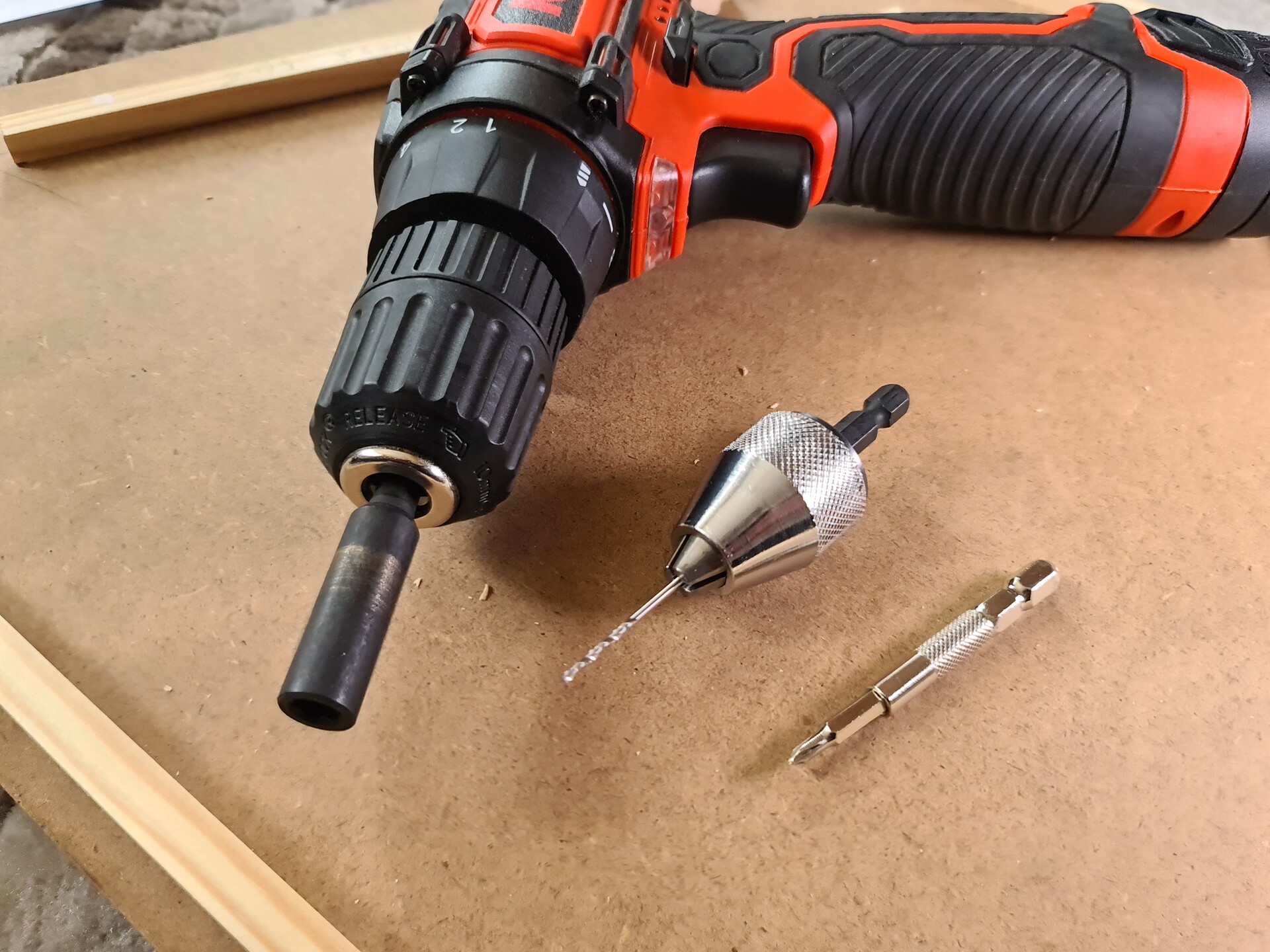
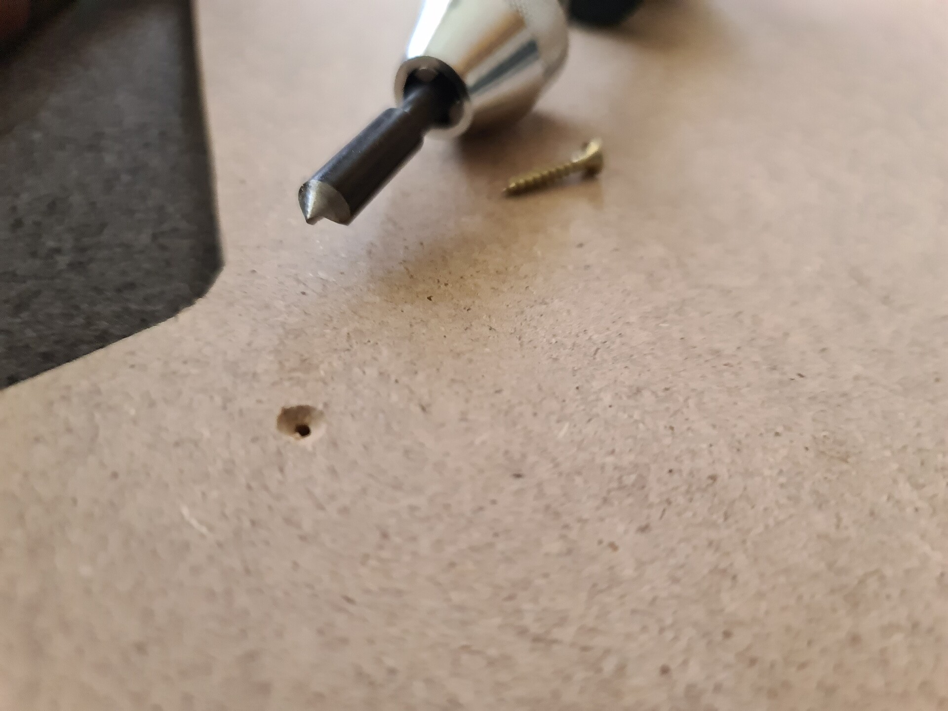
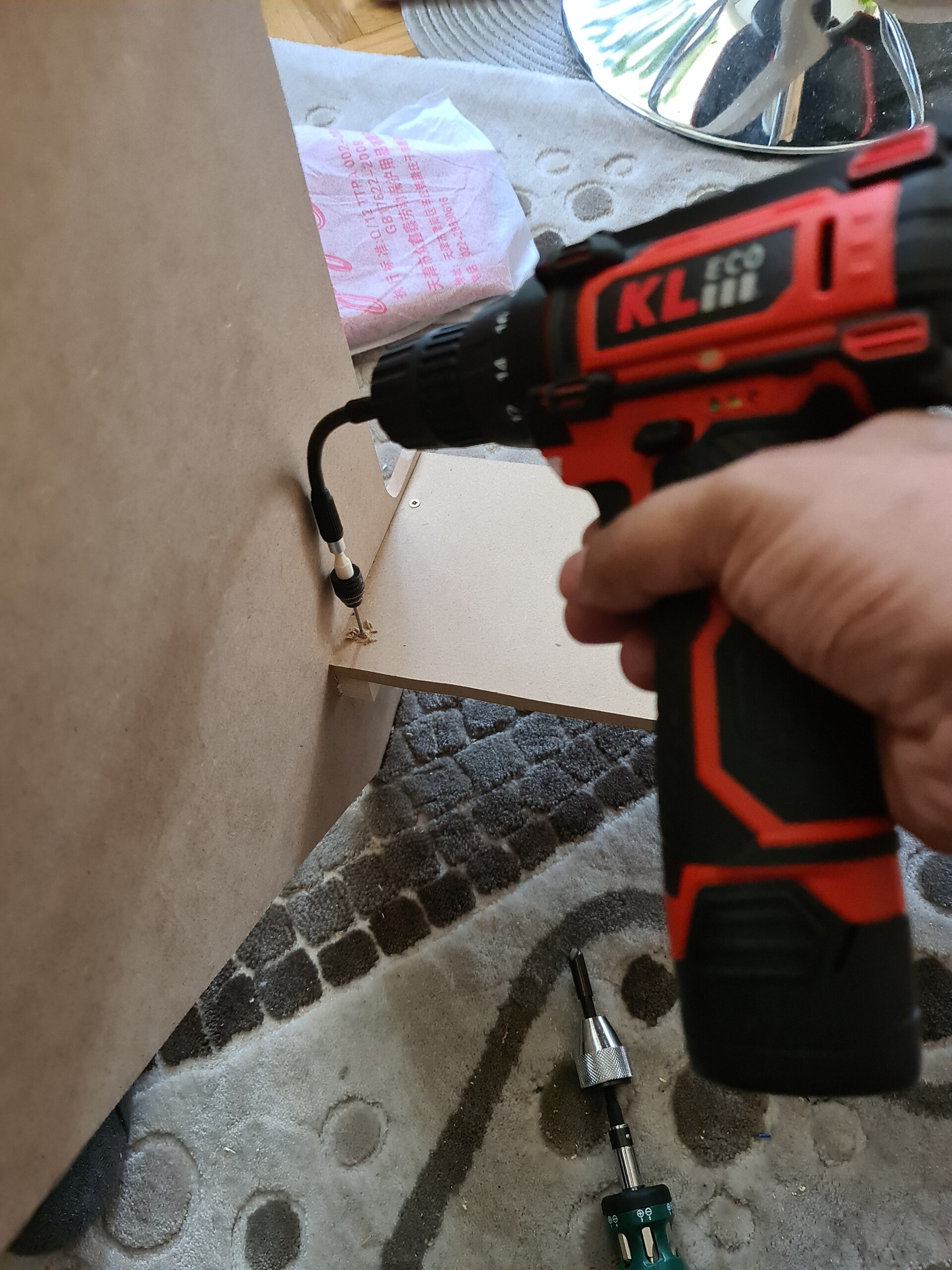
To make the 90 degrees connections I used a hand drill to make the hole for the self tapping screw, and then drive it through.

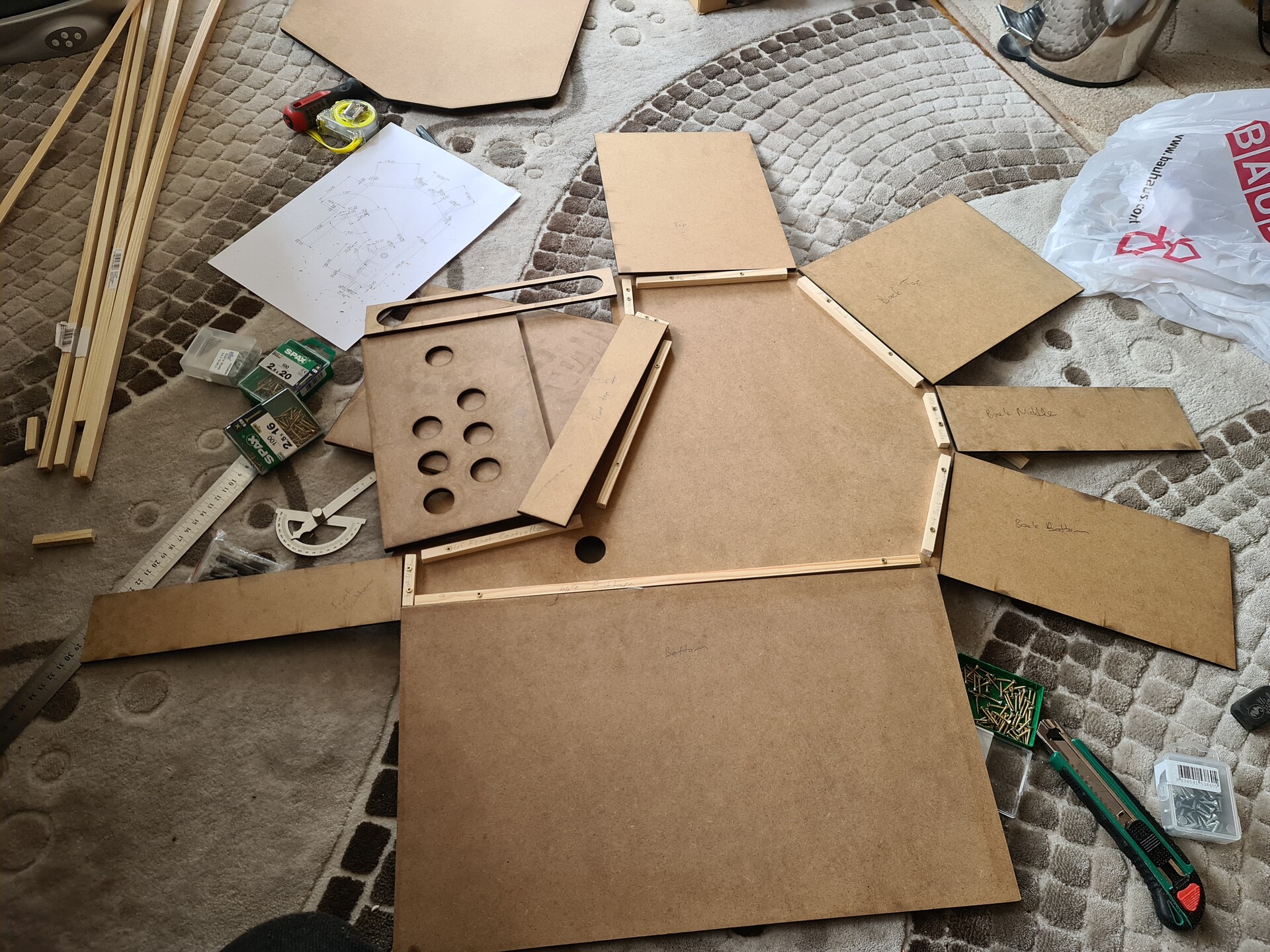
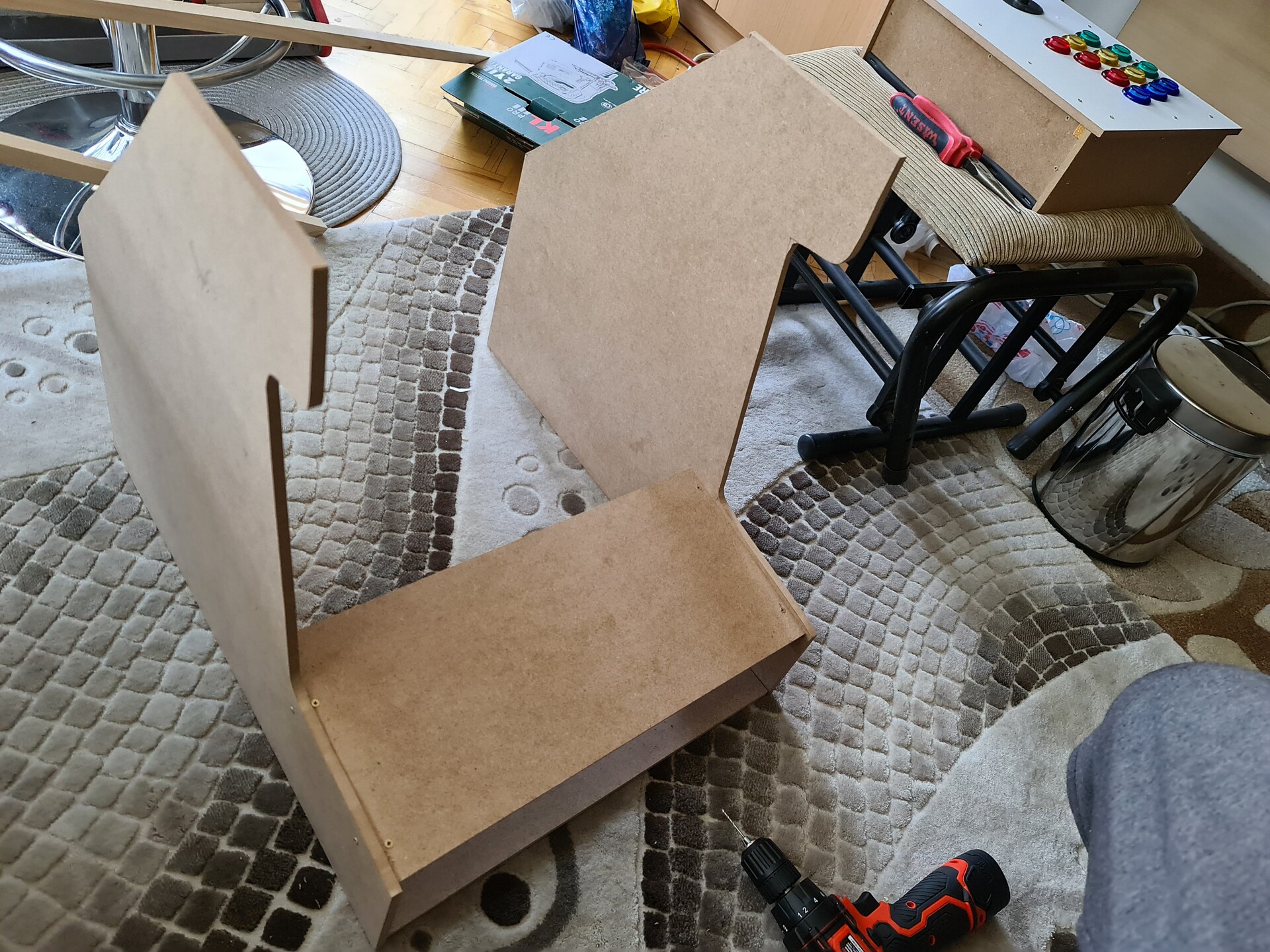
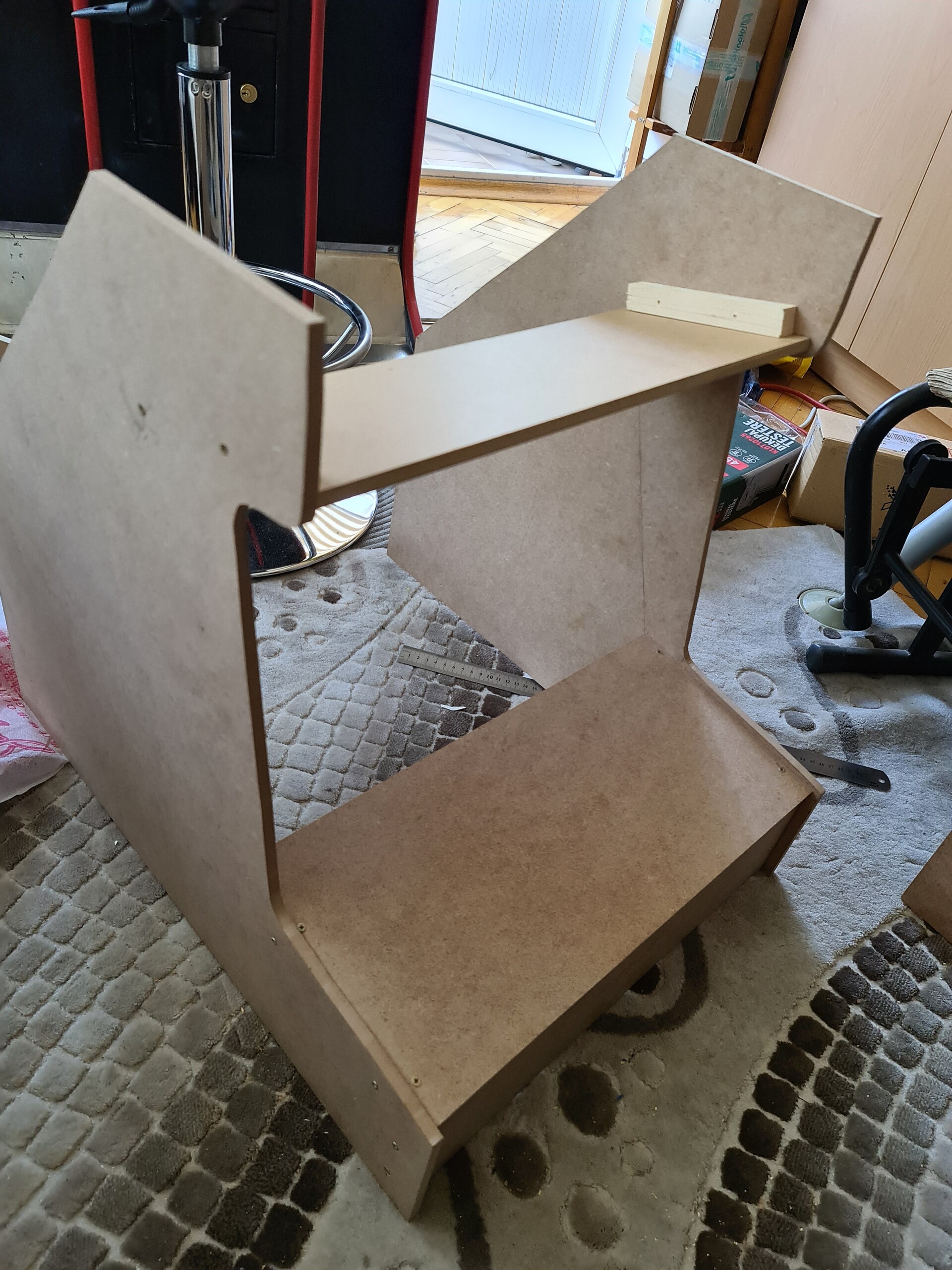
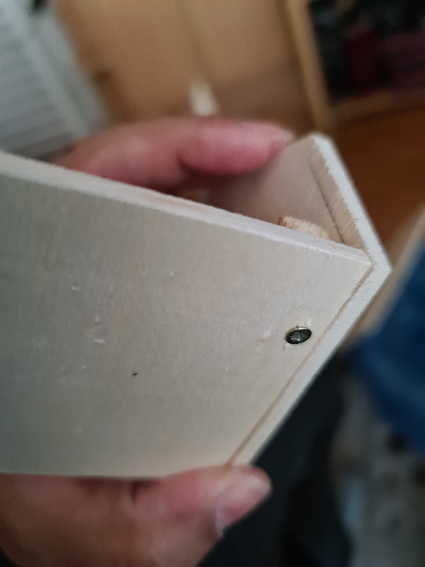
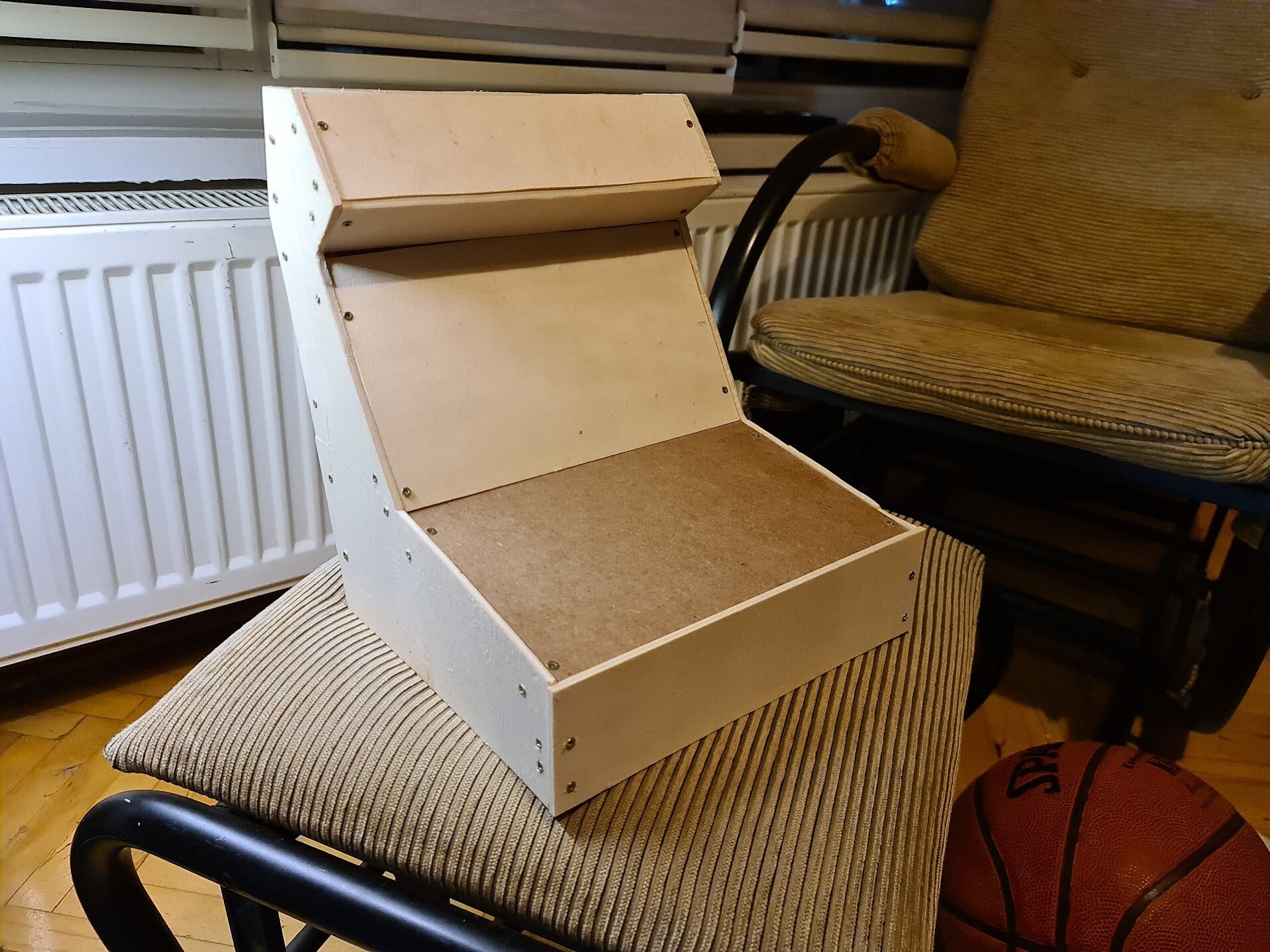
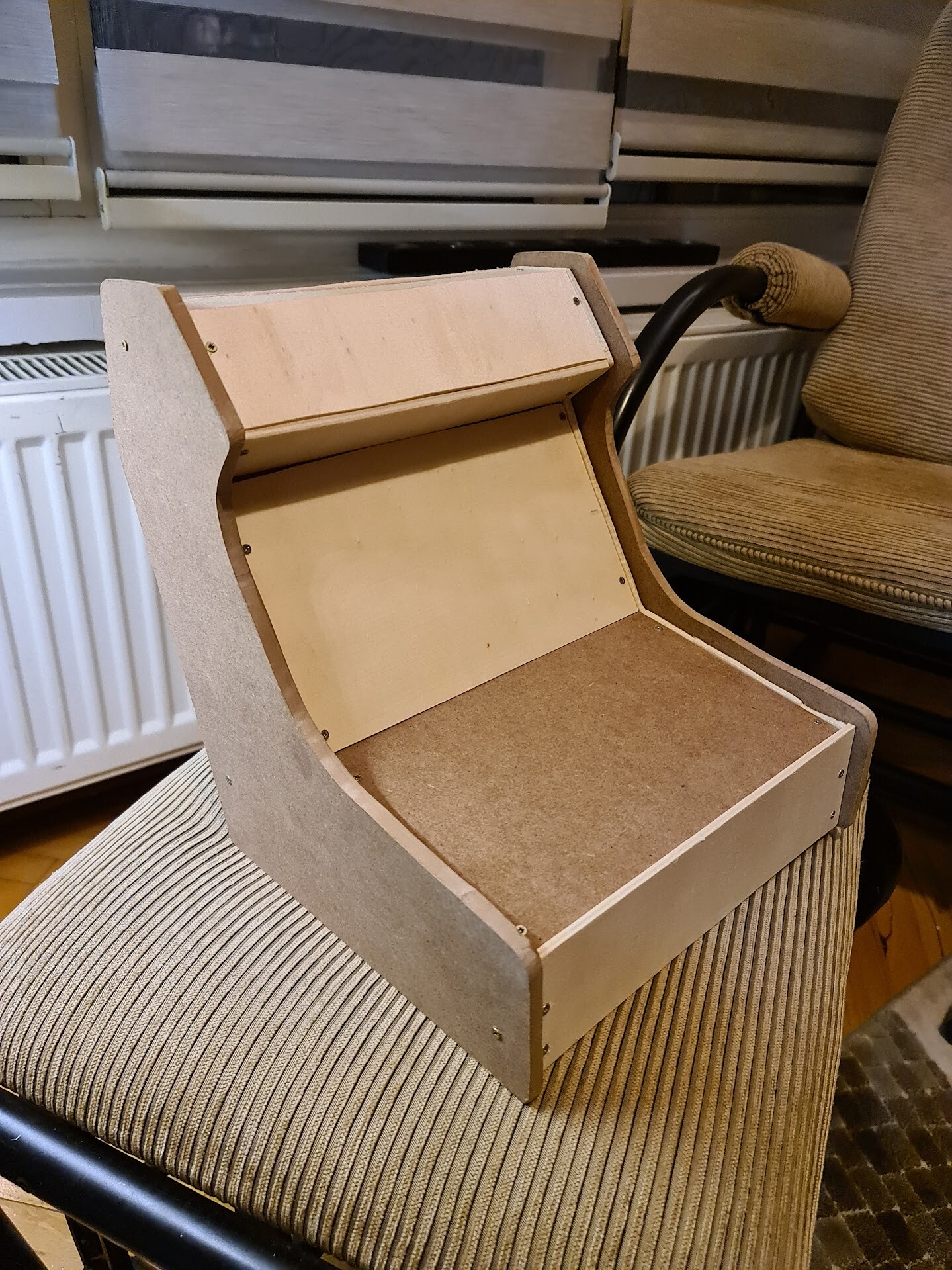
This is the look of connected boards, which made me happy since it's my first experience to work with wooden material like this.

I cut the rest of the planar boards with a saw.

And connected the rest of the boards. Result is like this:

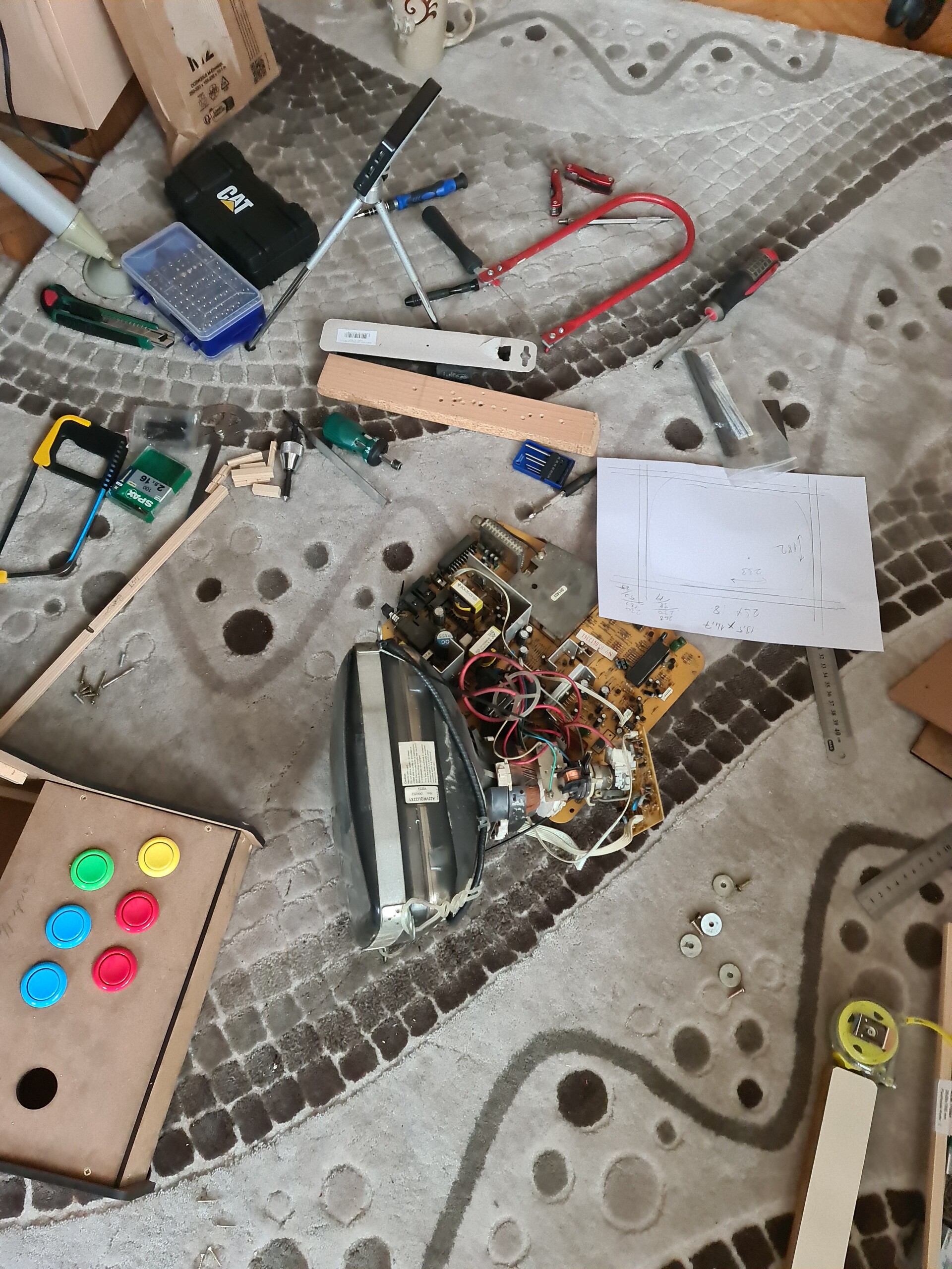
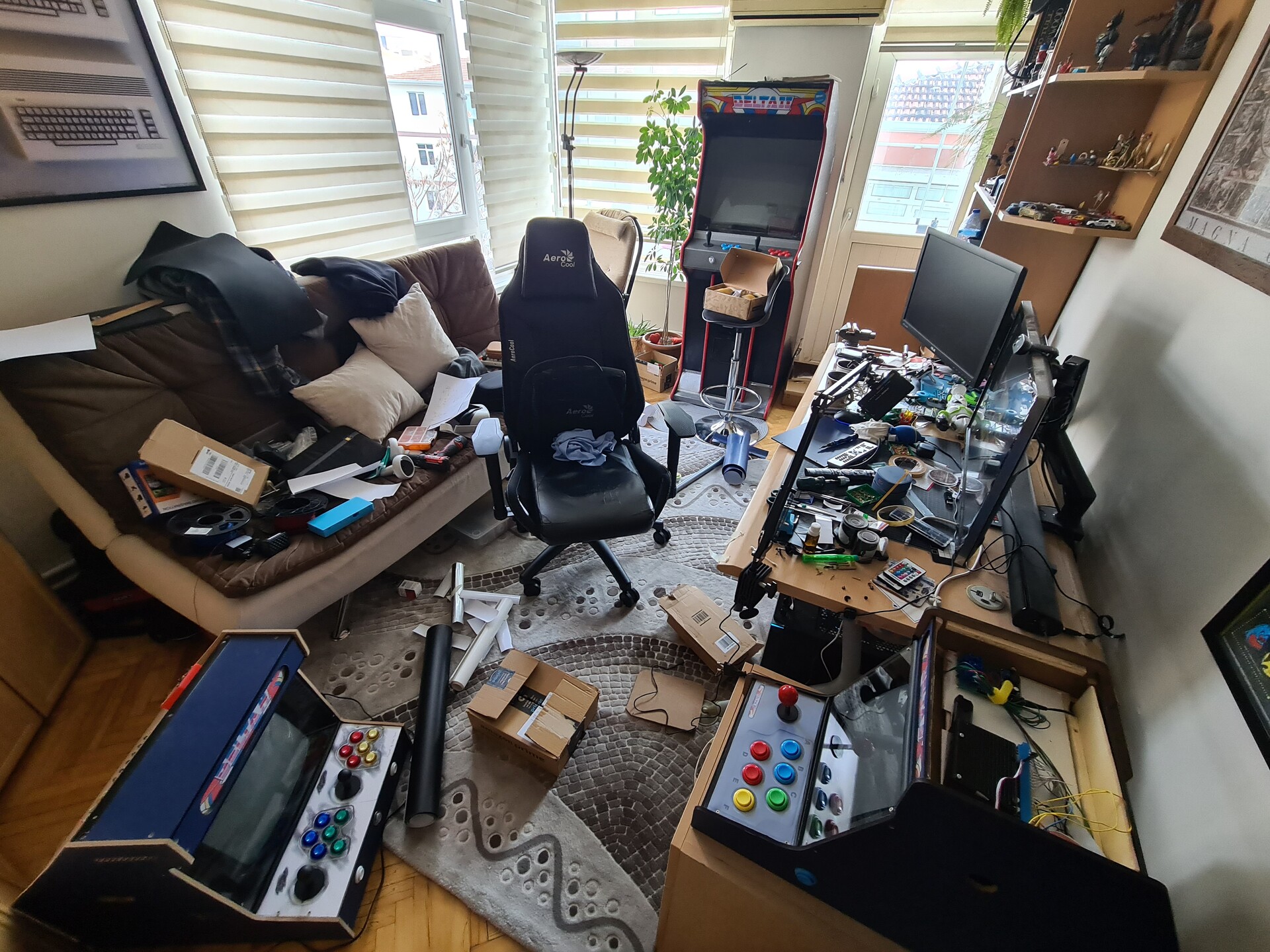
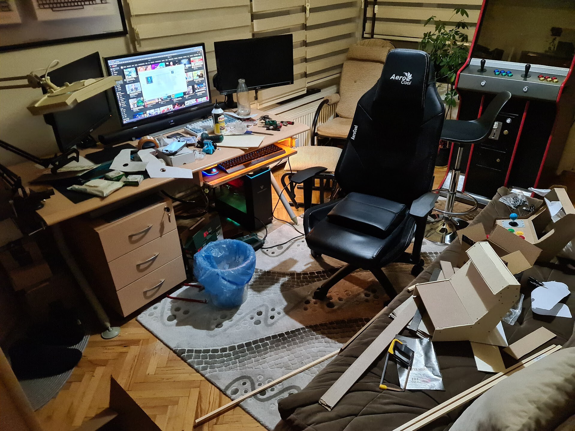
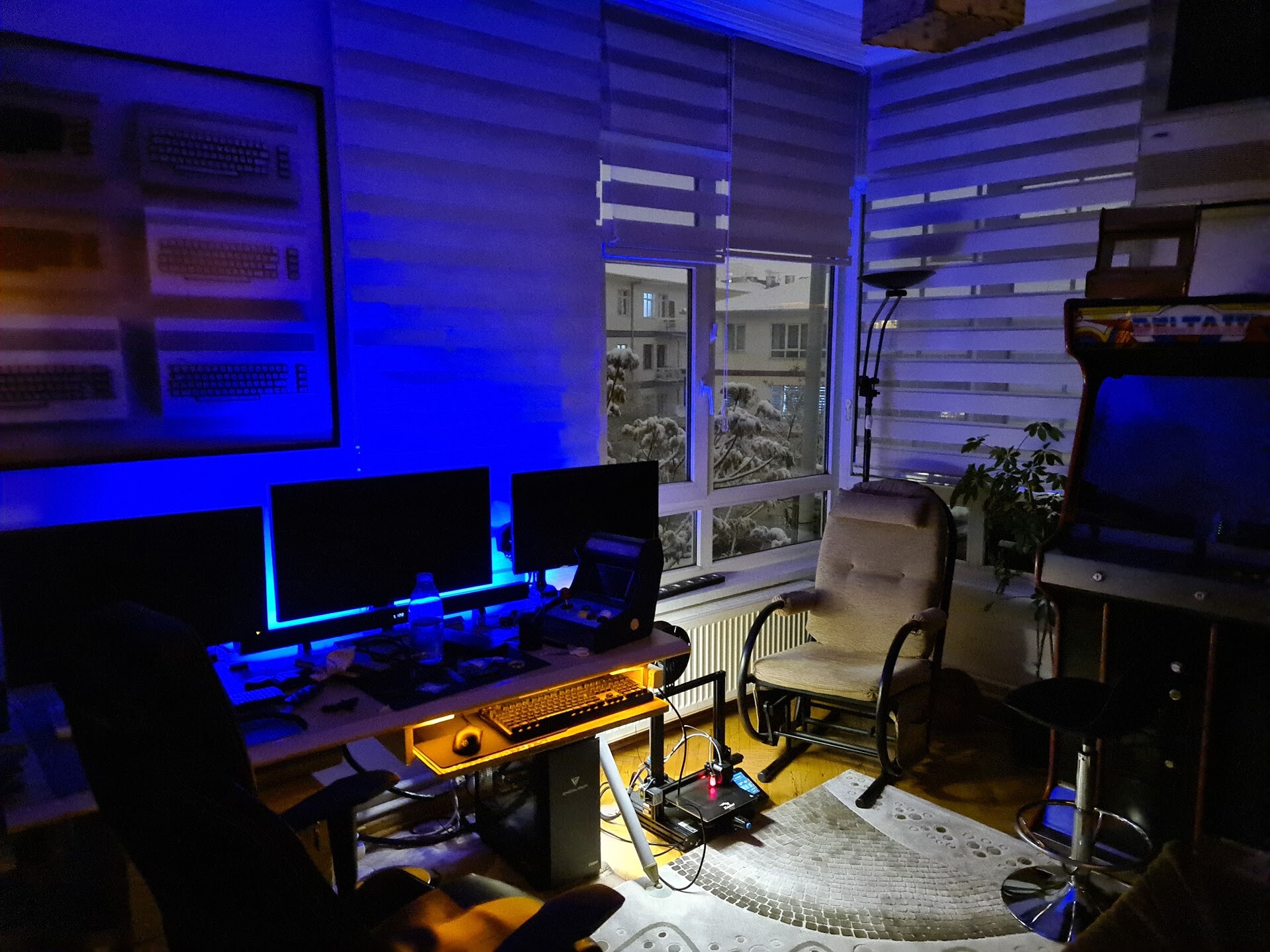
My workspace is kind of messed up.

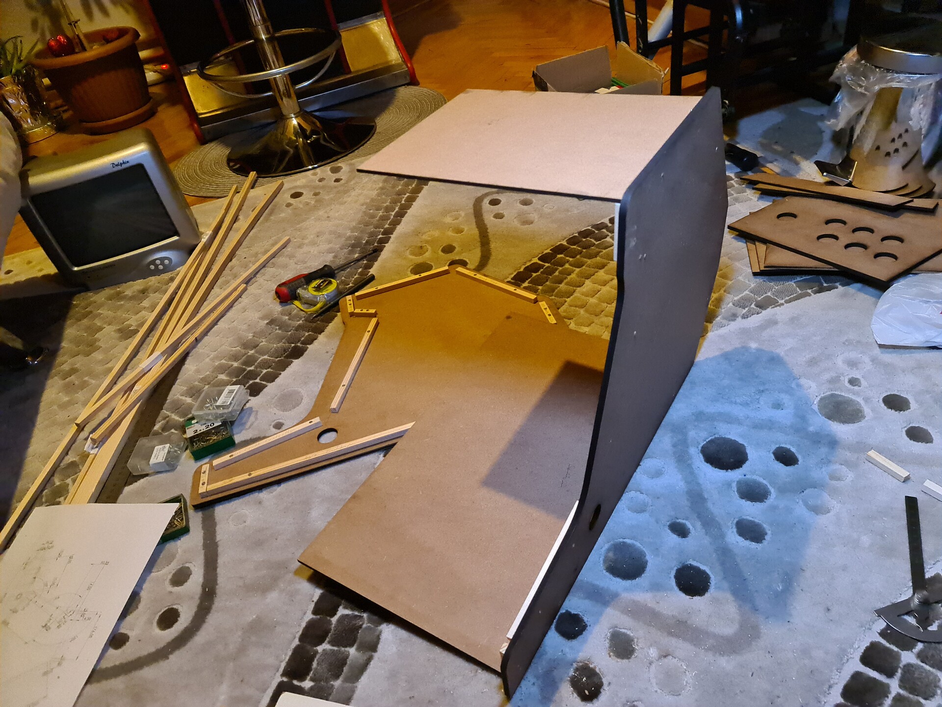
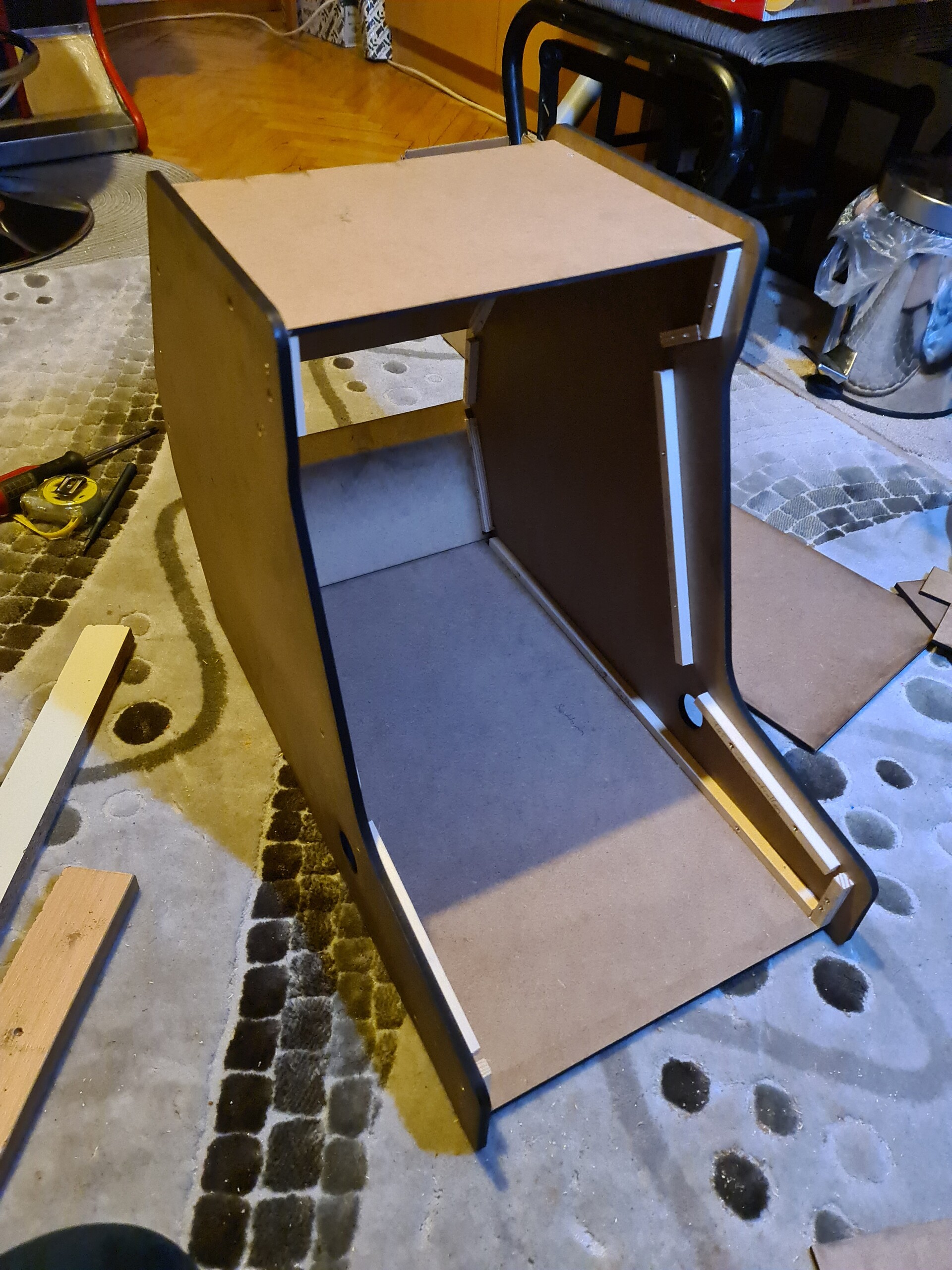
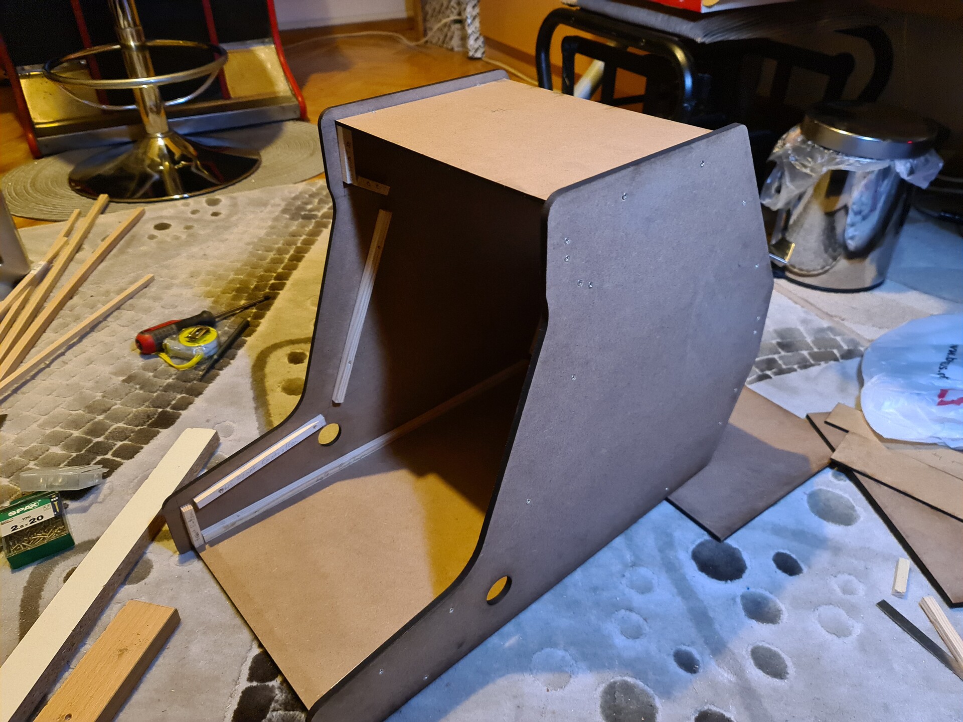
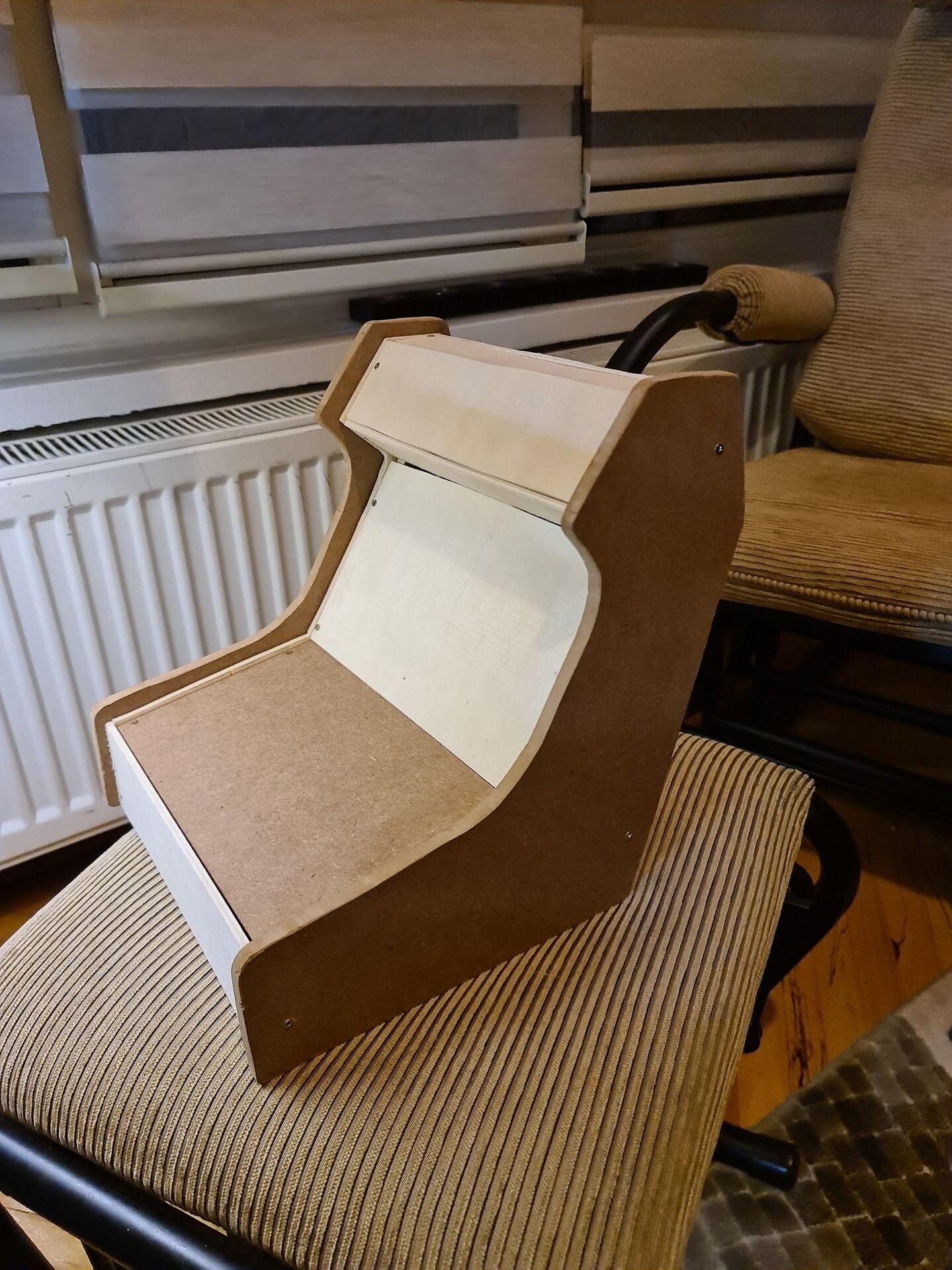
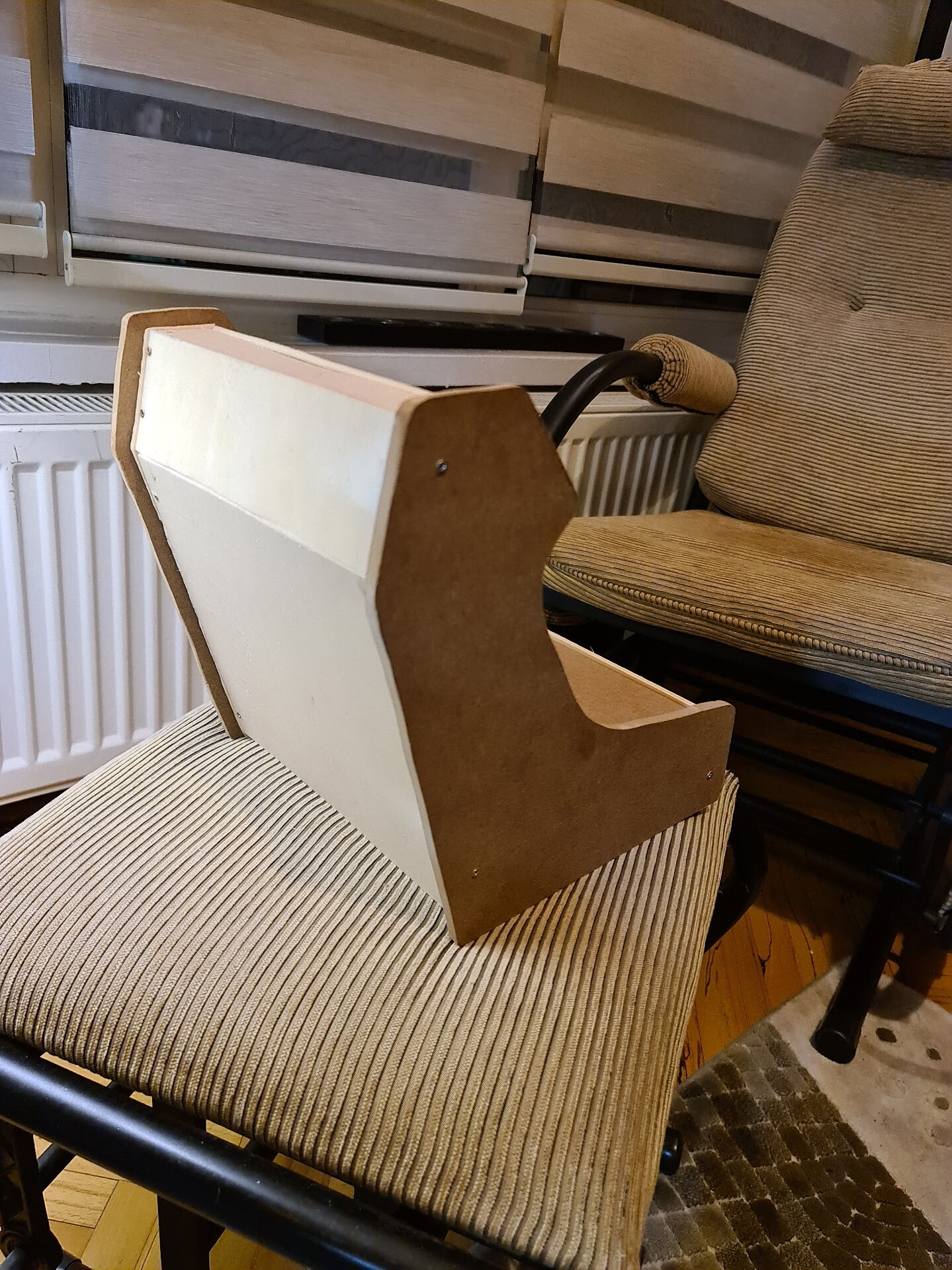
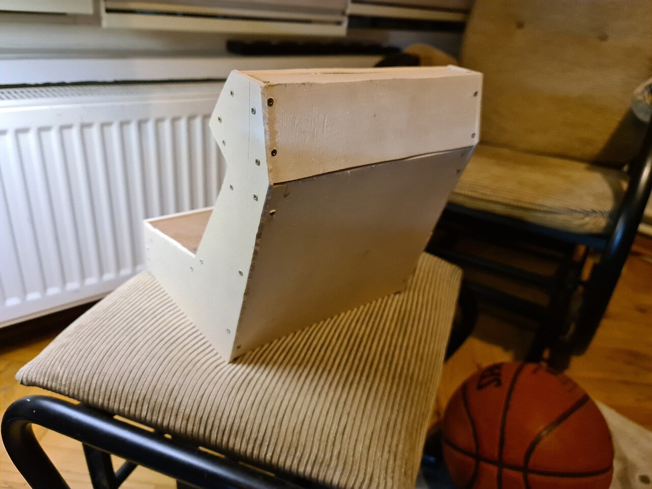
Now it's time for the side boards with 8mm MDFs. I used the same templates I used for the cardboard process to draw the border of cutting.

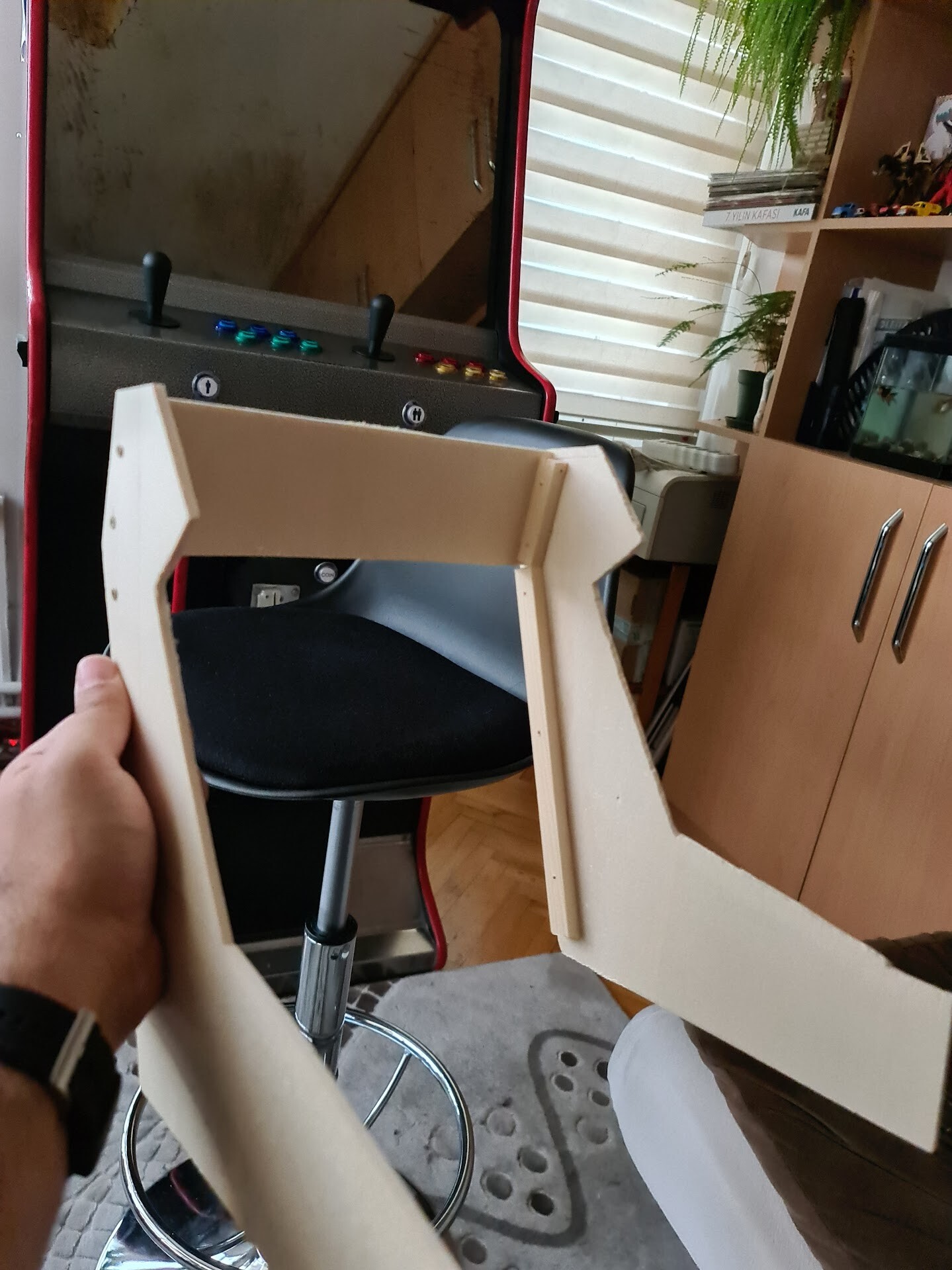
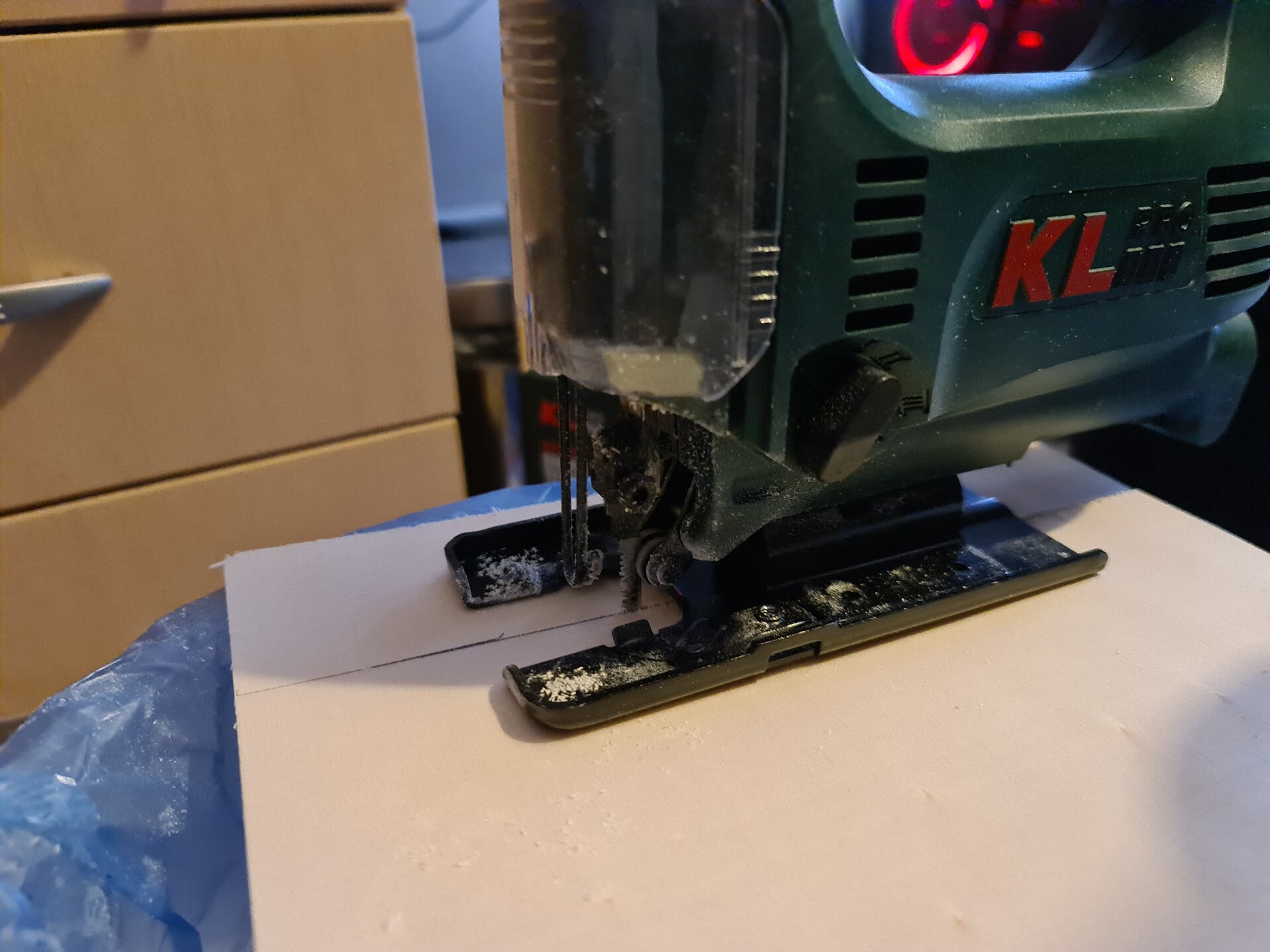
I used the same automatic saw to form the curvy sides. I wasn't so sure but it worked good since it's a flexible saw.

So I mounted the side boards too.

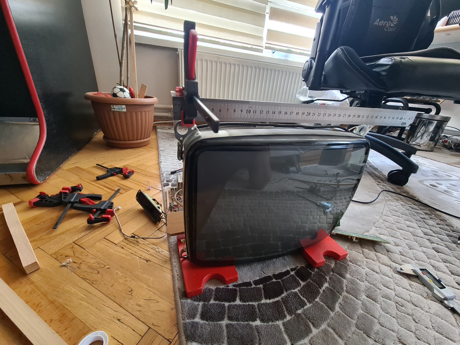
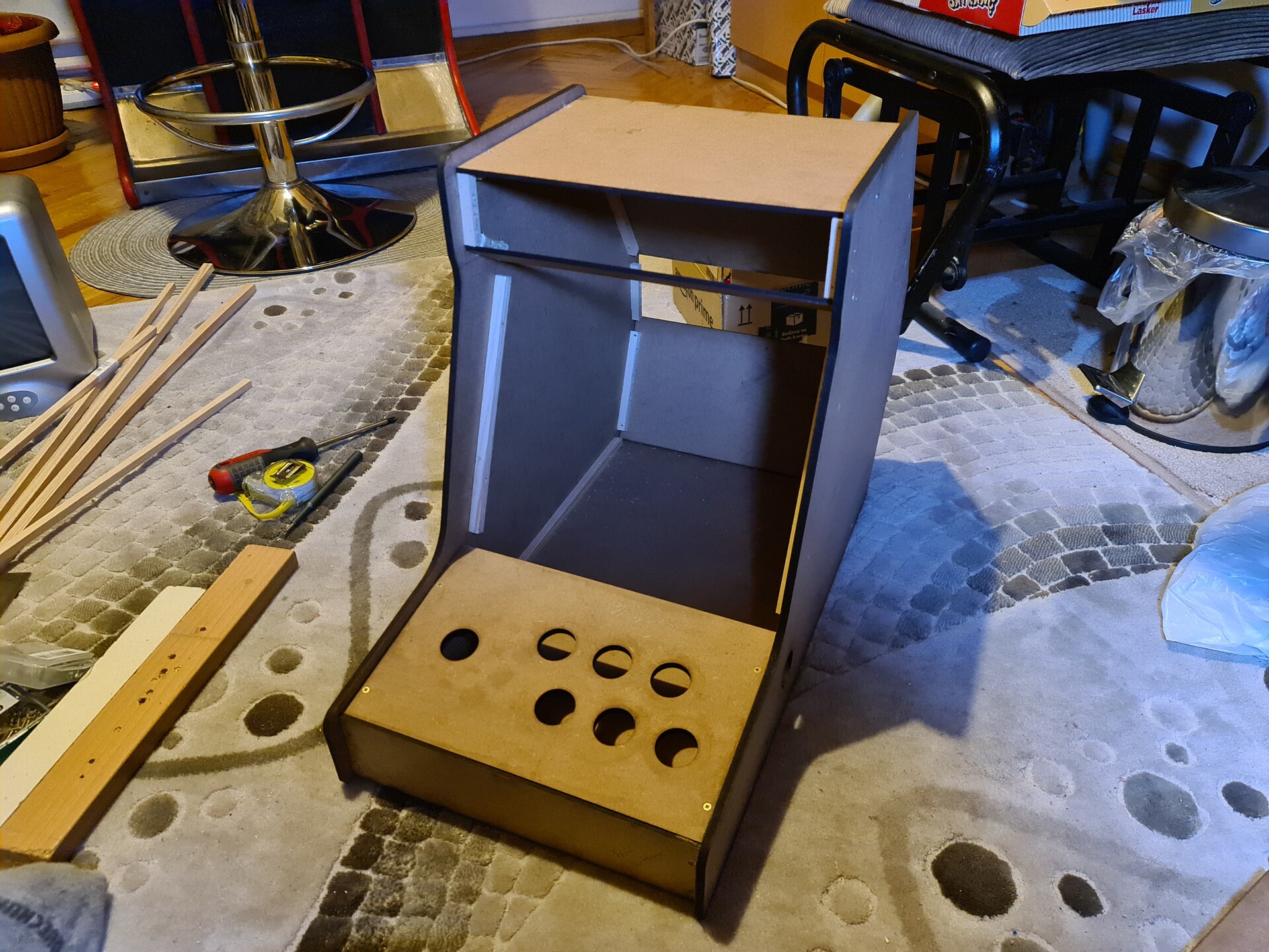
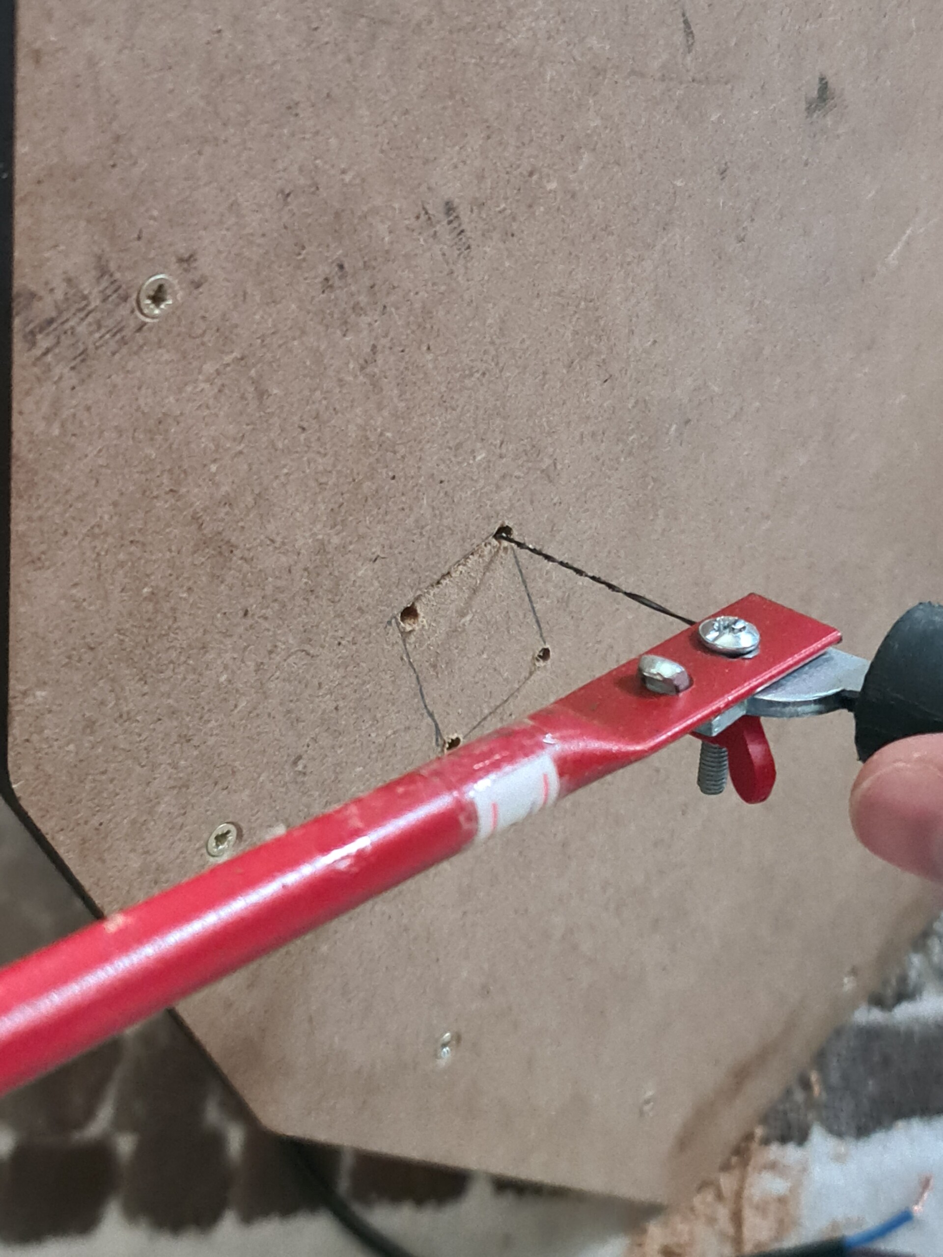
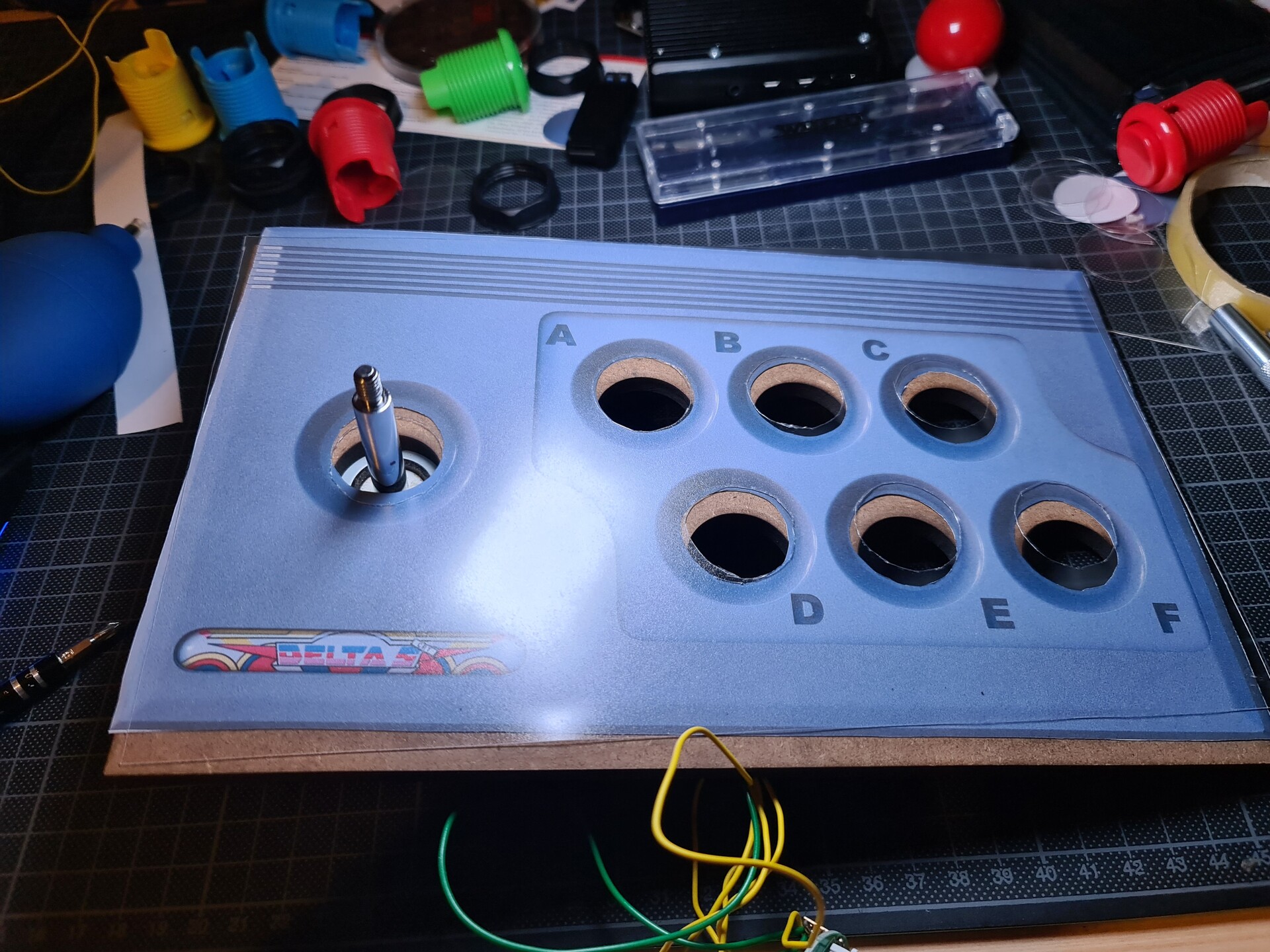
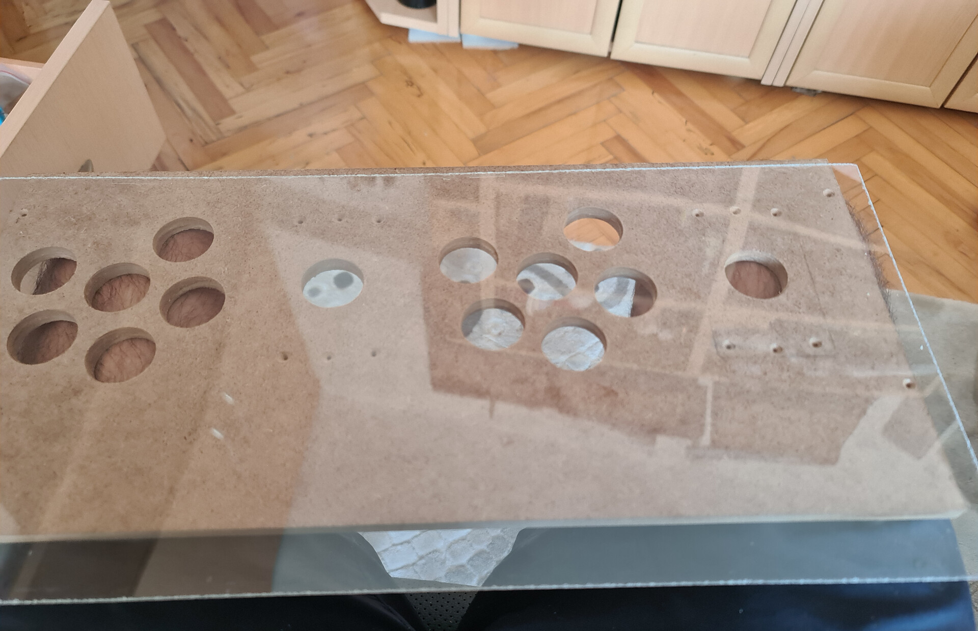
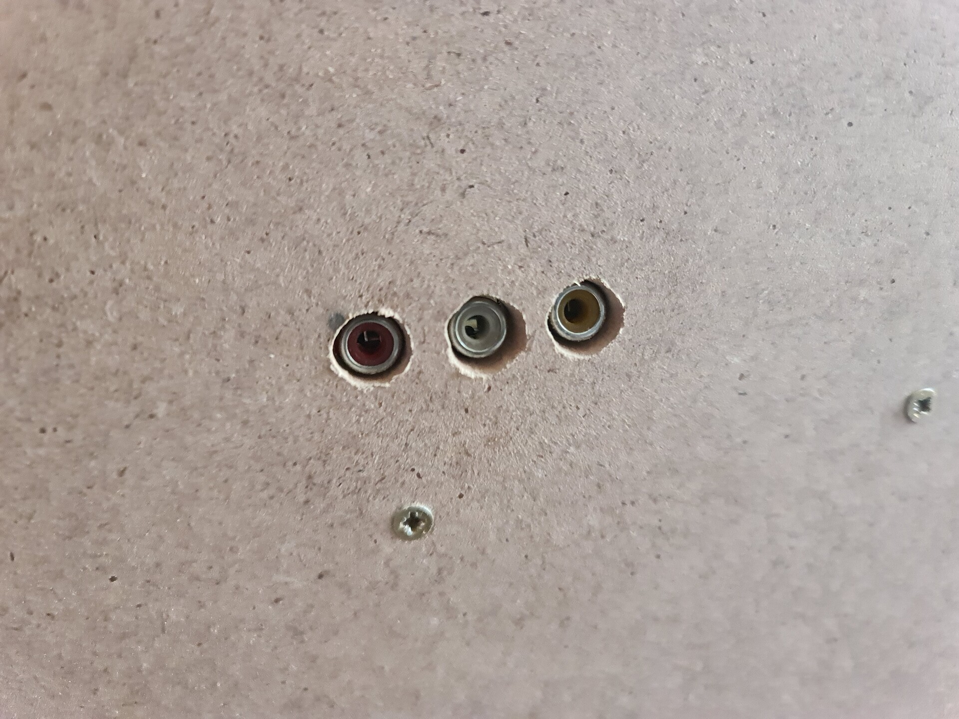
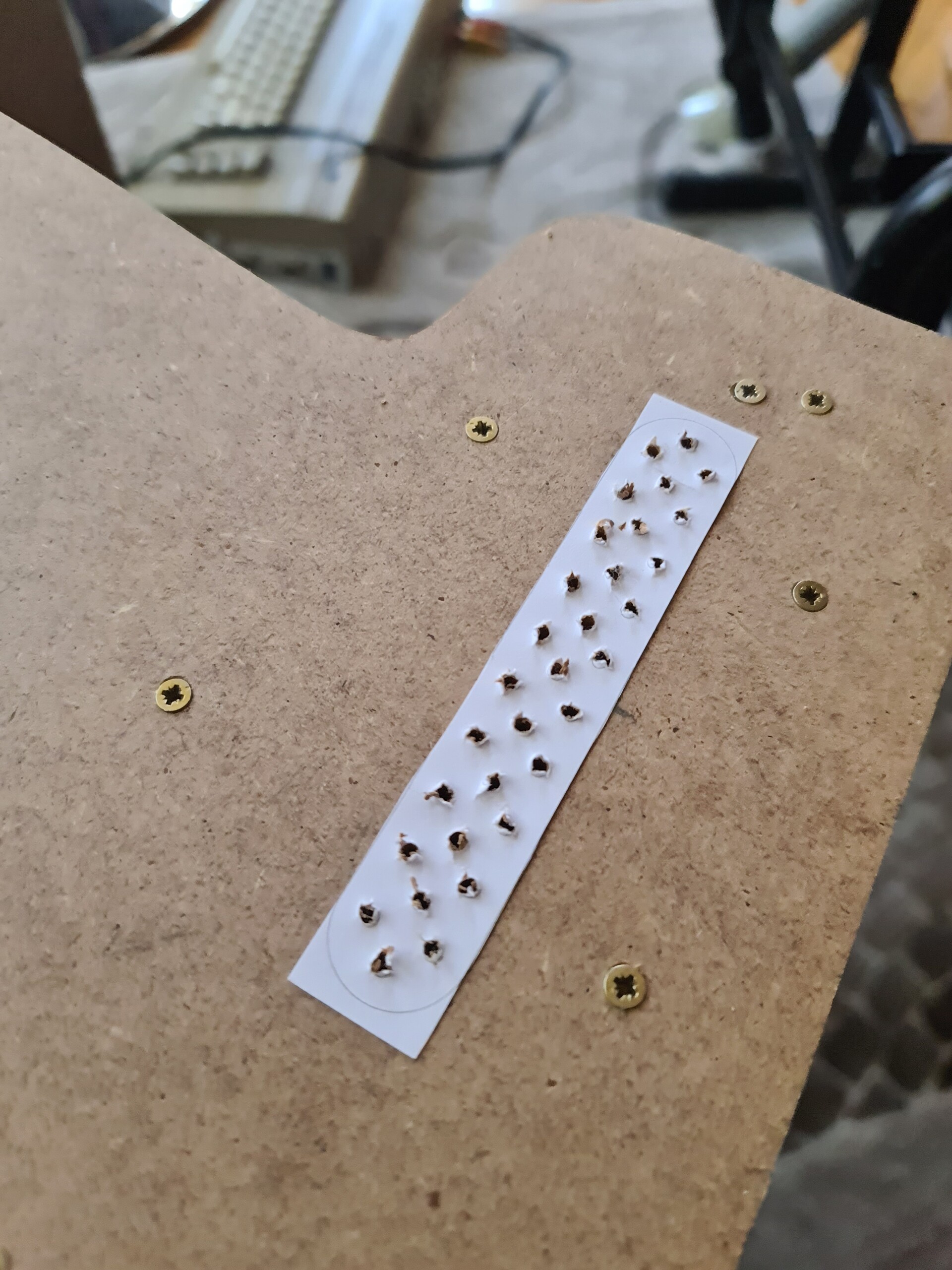
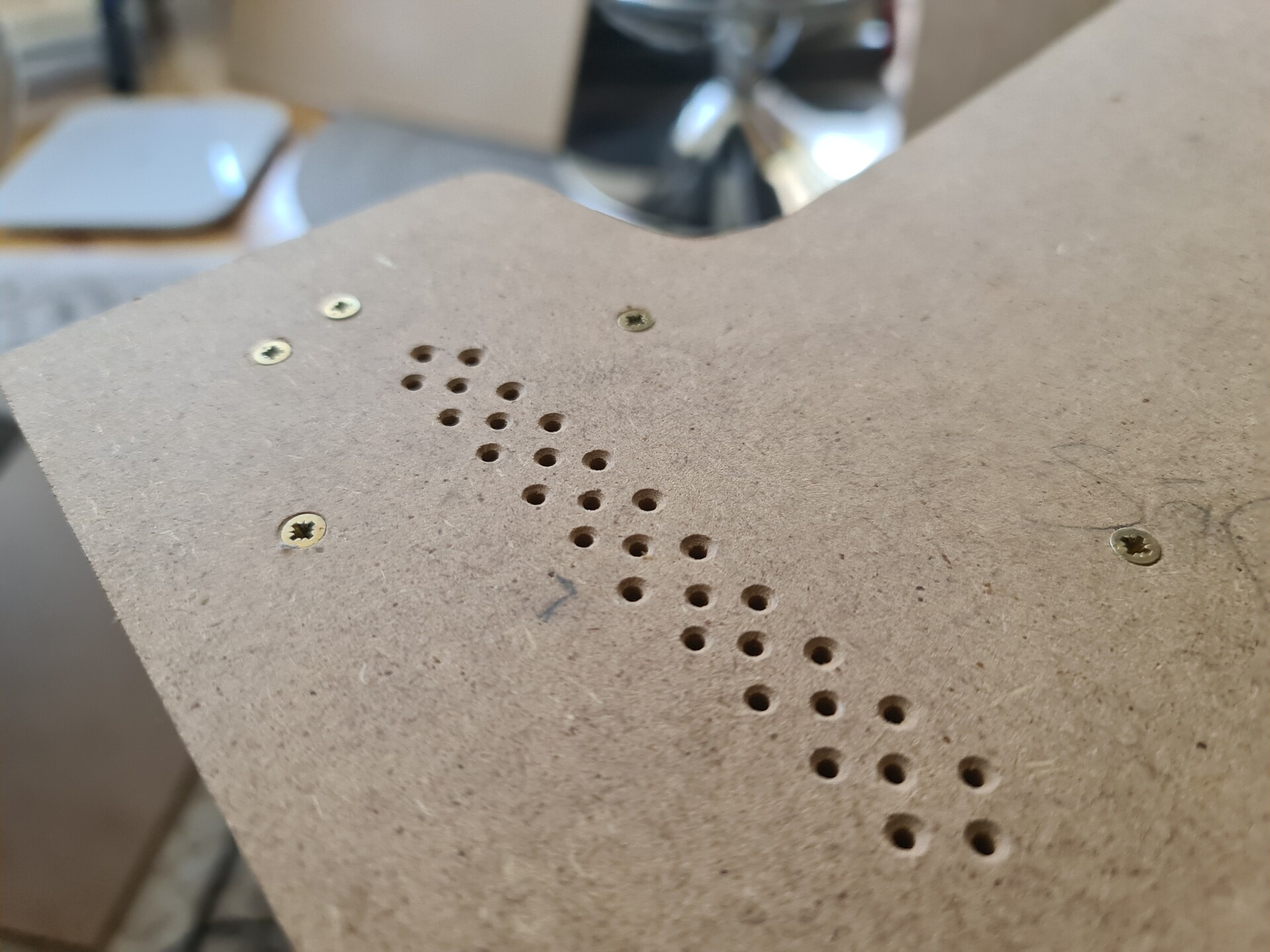
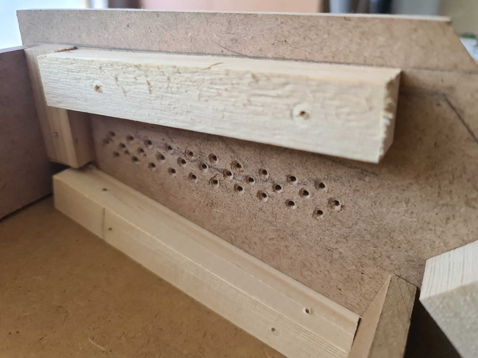
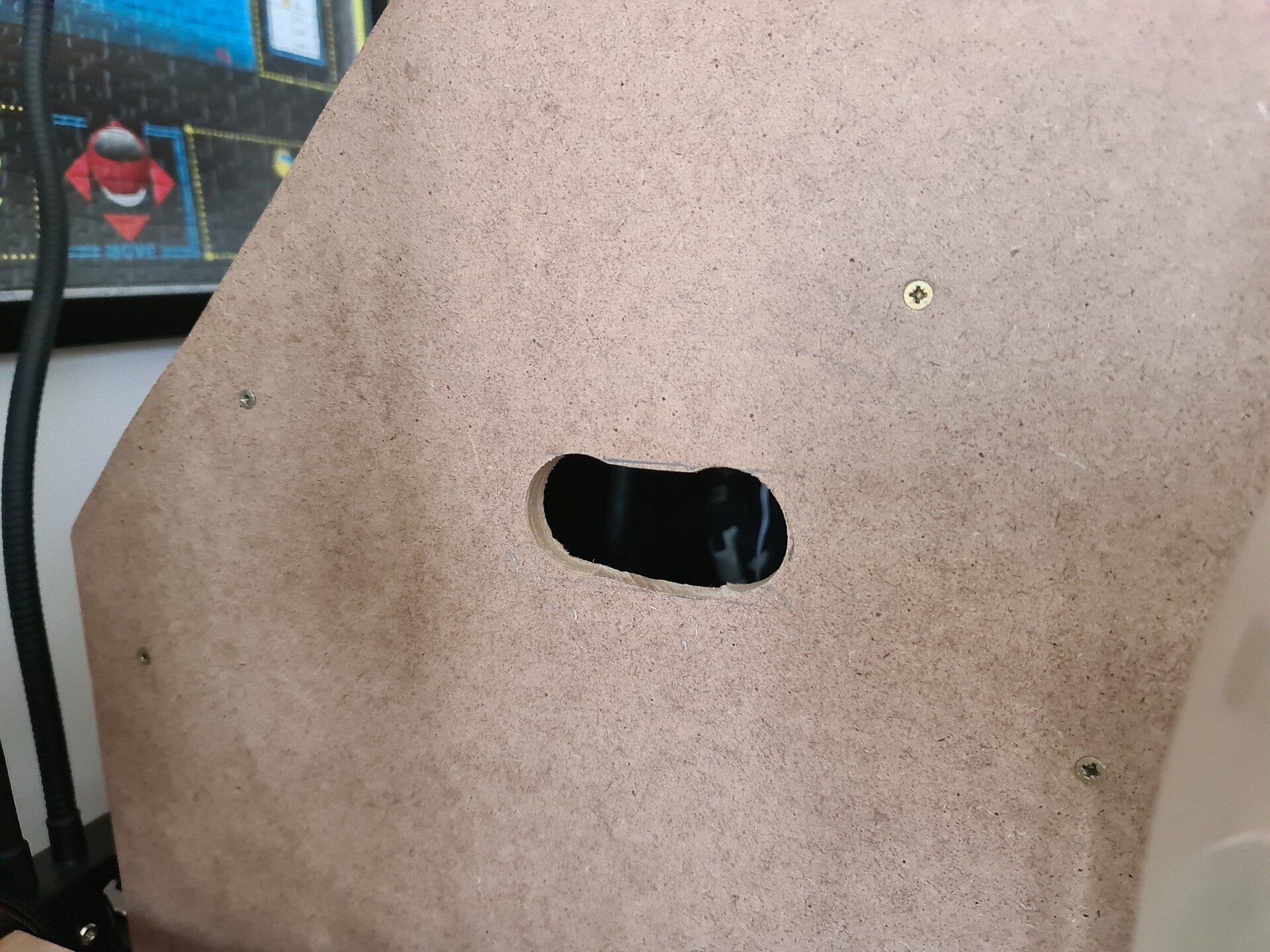
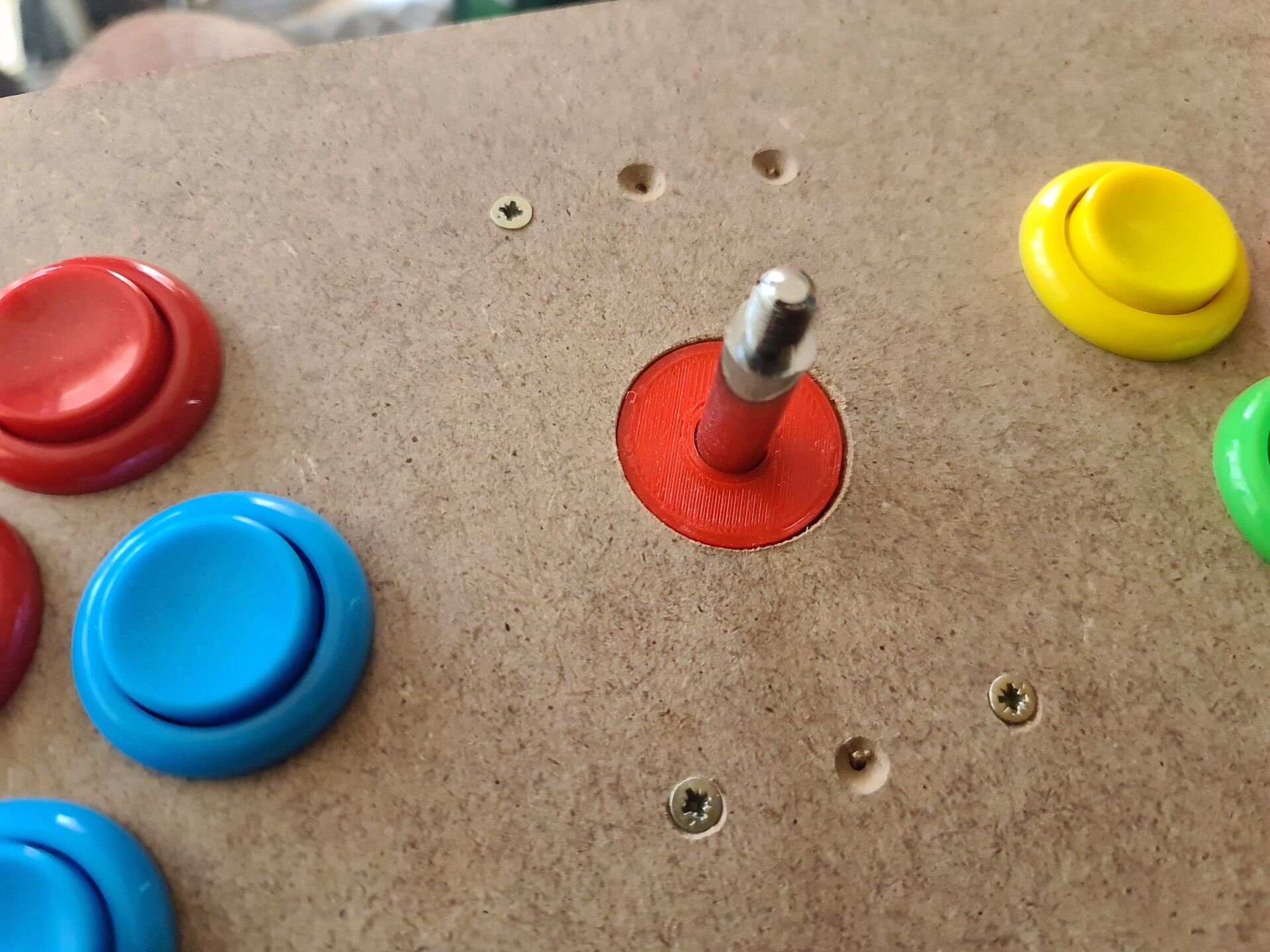
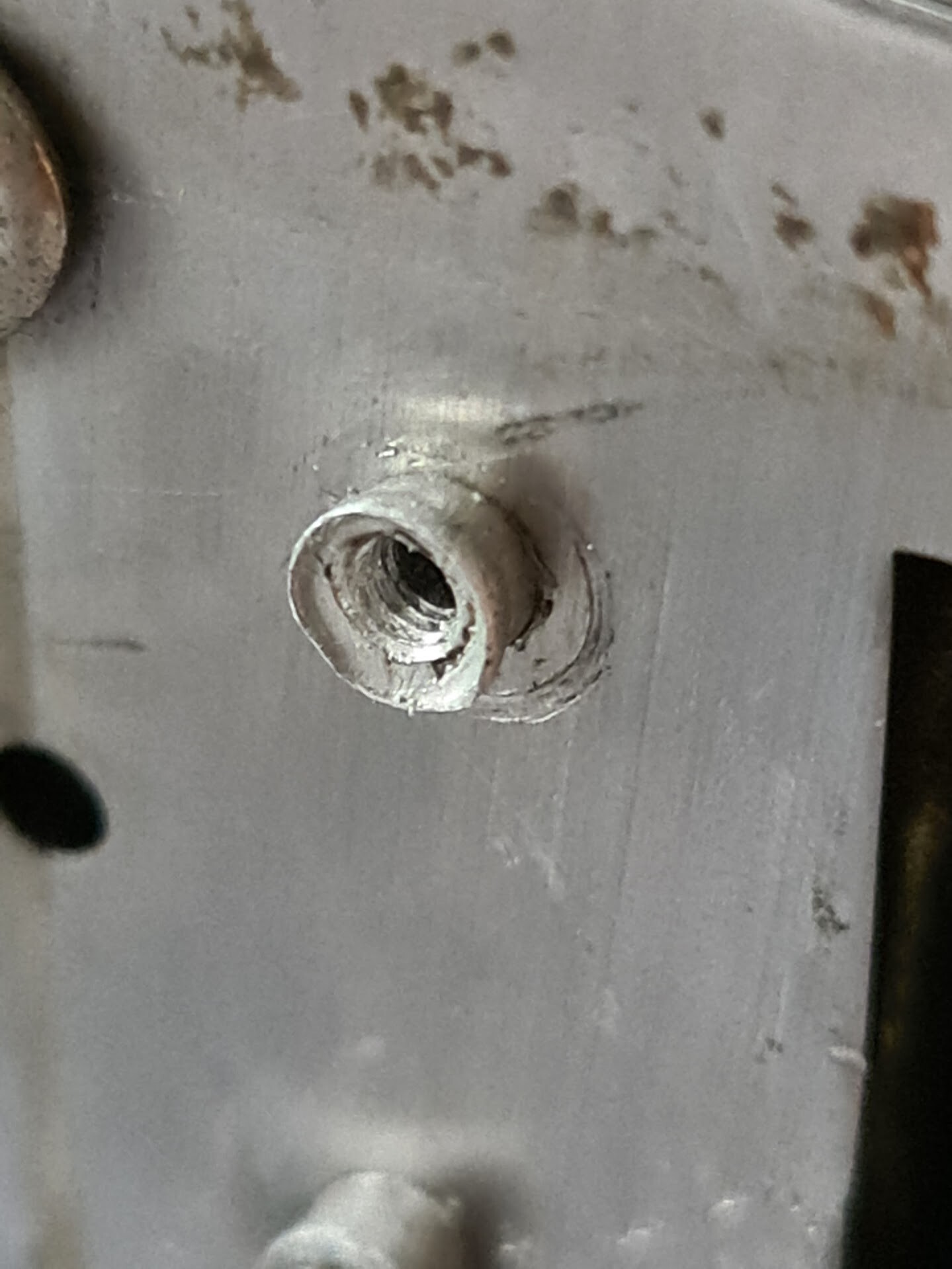
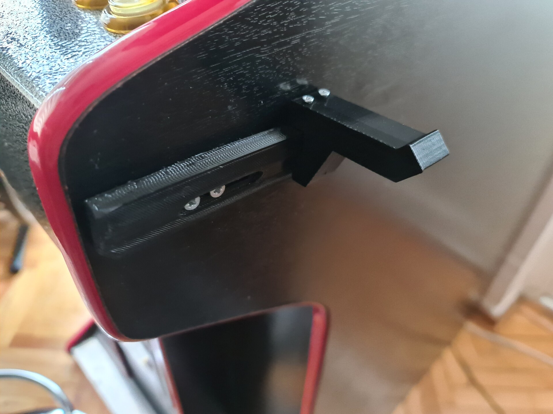
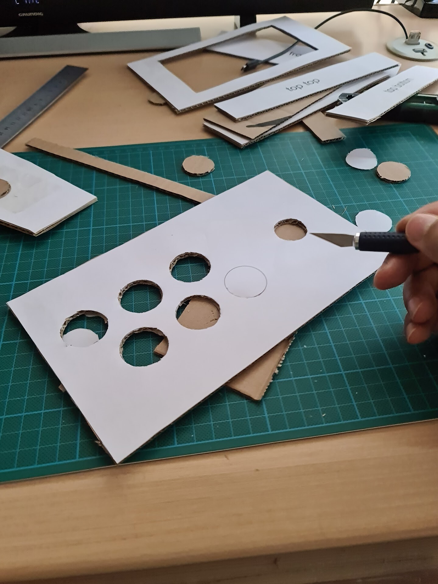
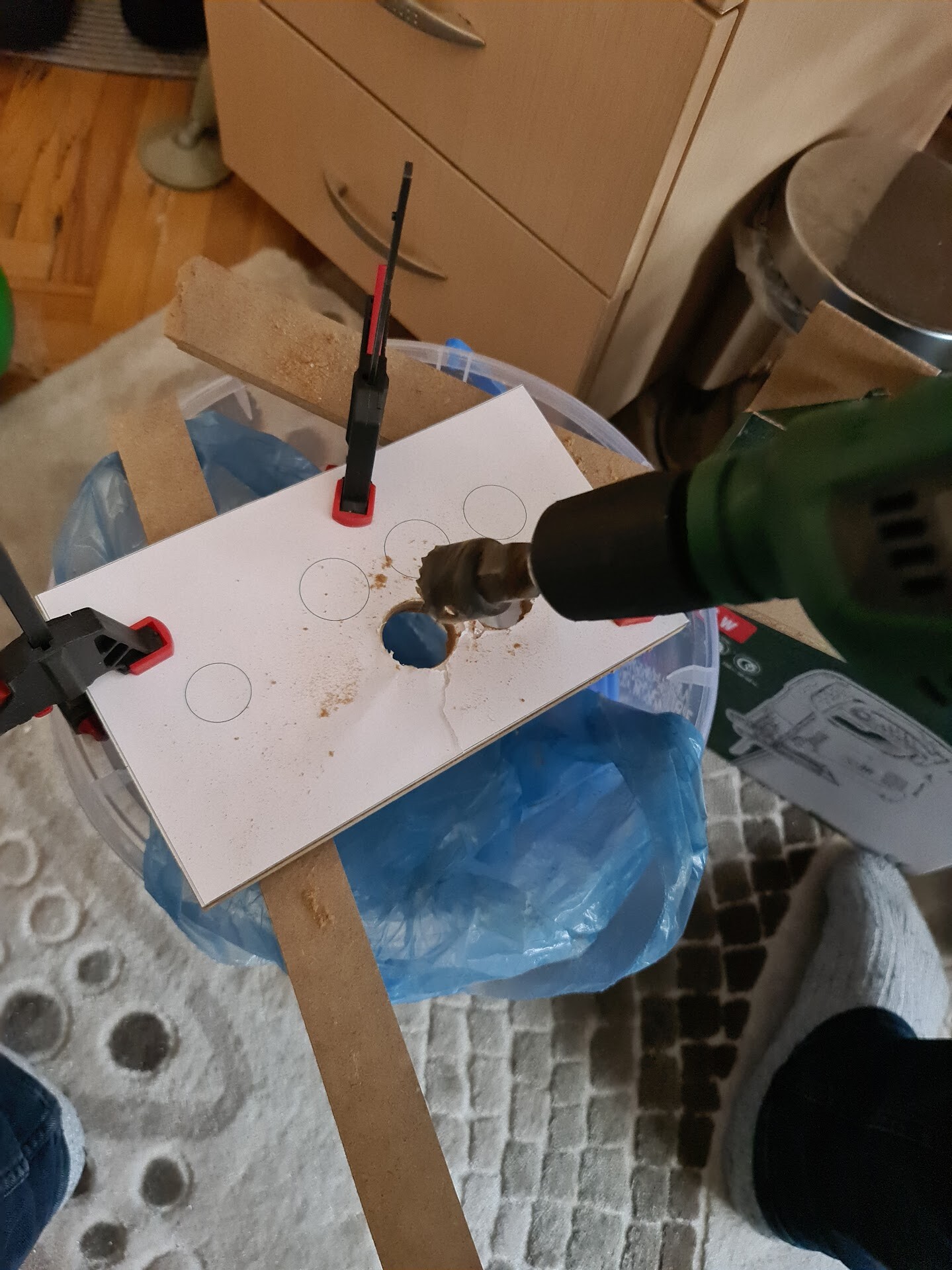
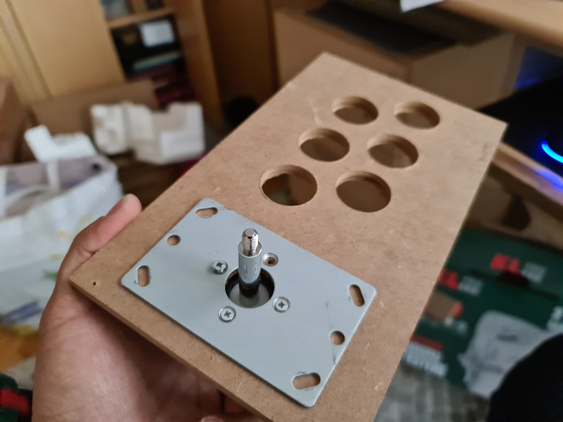
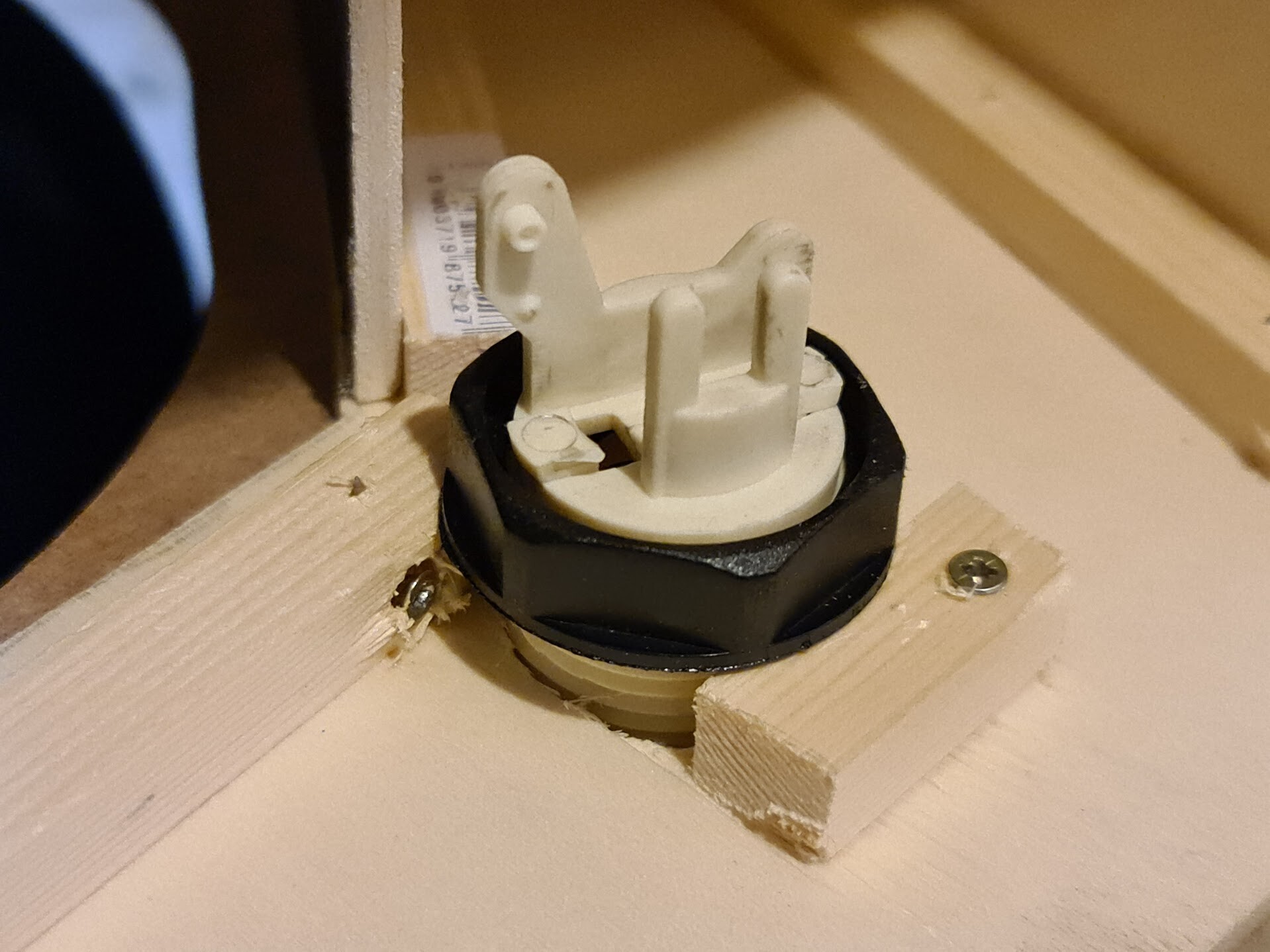
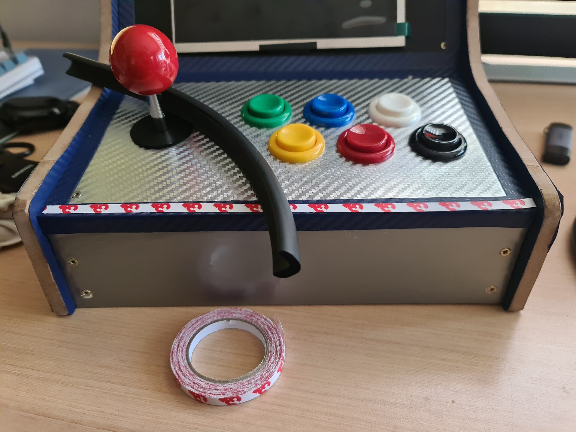
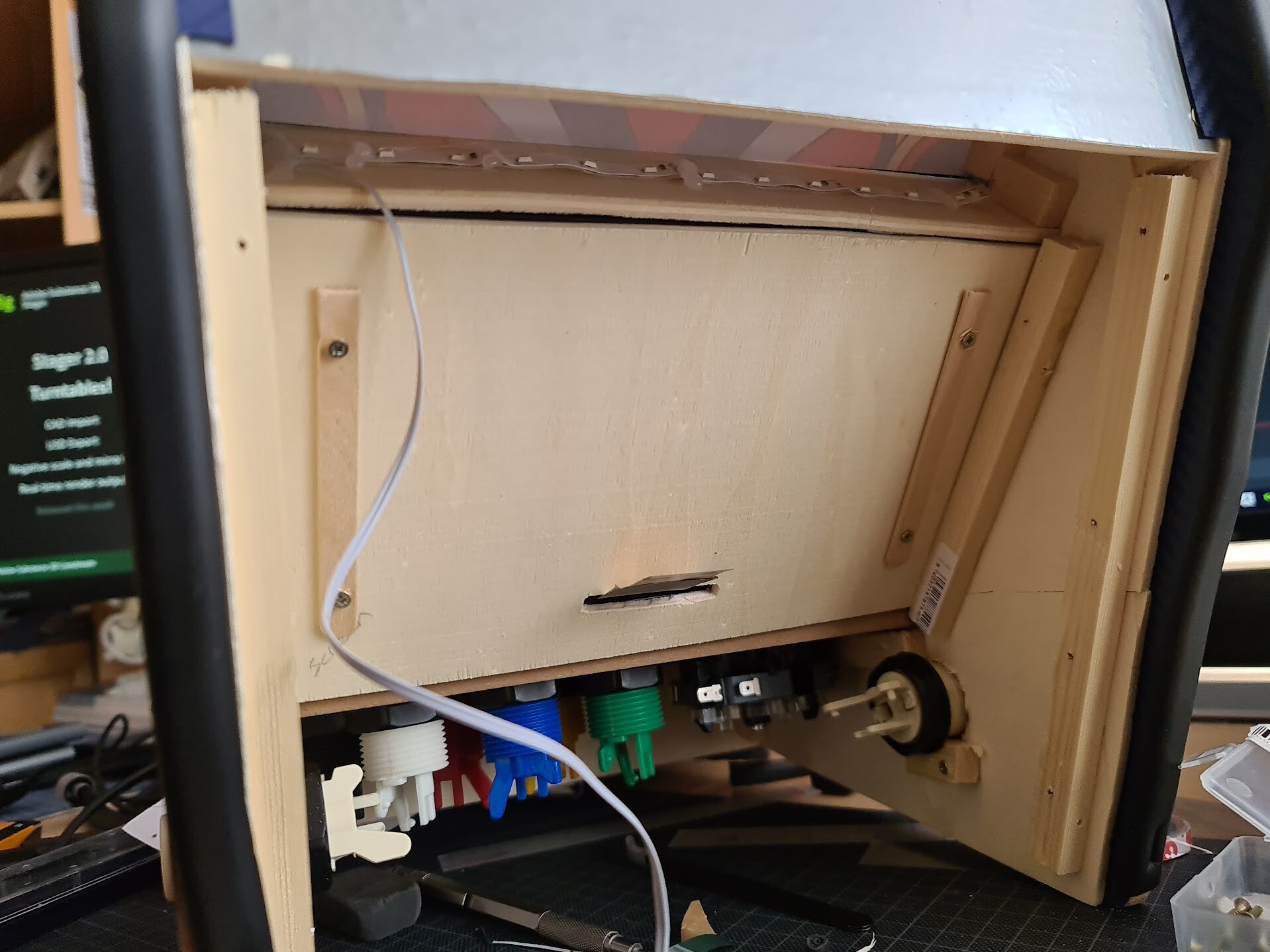
After this part, I drilled the holes for the button and the joystick.

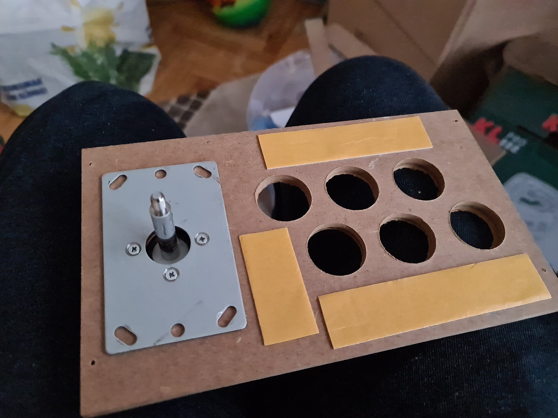
Since the joystick I have, has a metal plate to screw to the wood from top, I ended up with a thickness on the top of the 8mm board. That was the reason why I also have 3mm white MDF. I used it to cover this metal sheet. I also applied some thick 2 sided sticker tapes to balance the thickness of the metal plate.

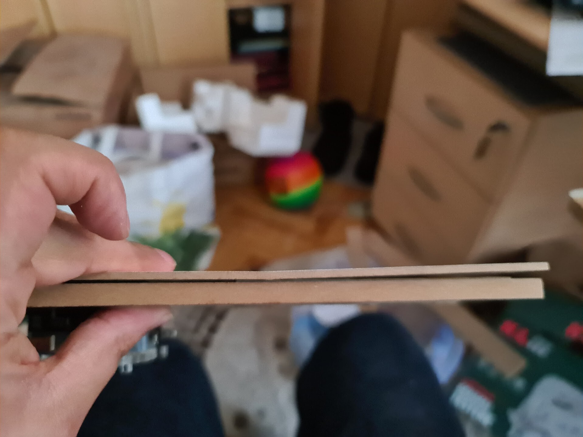
This is how it looks when I added the 3mm MDF over the 8mm MDF.

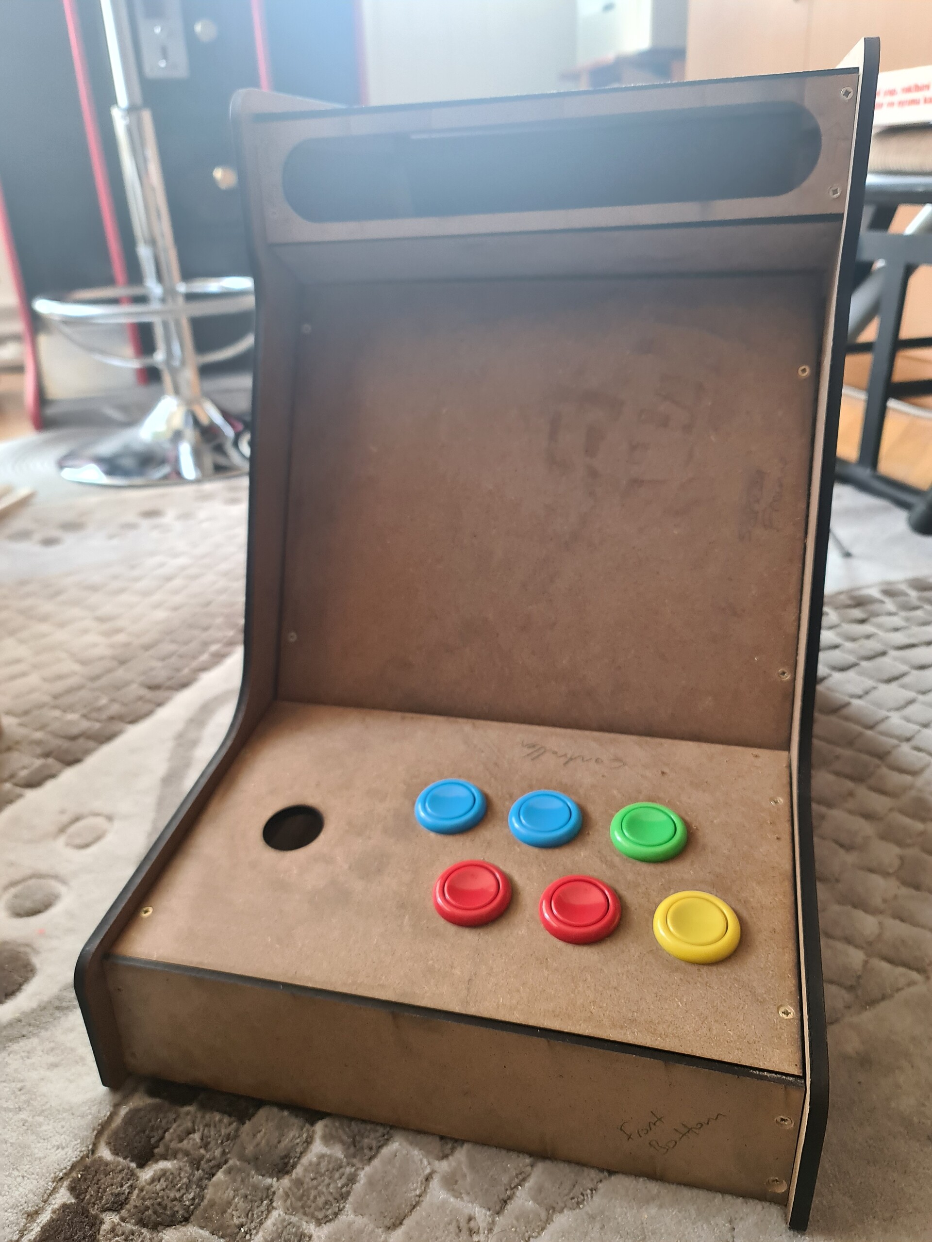
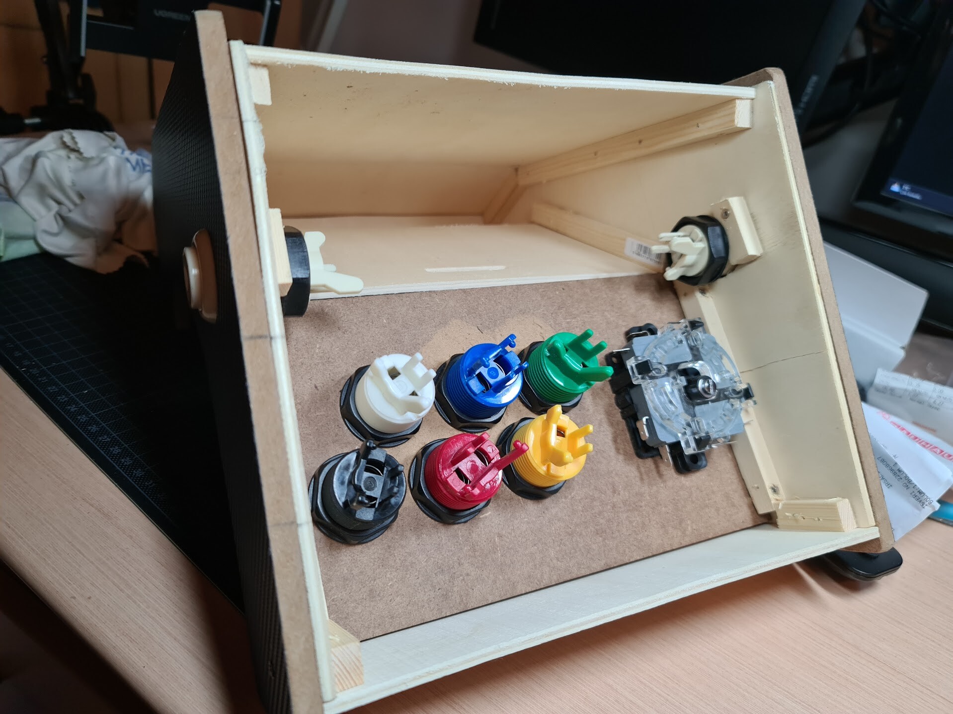
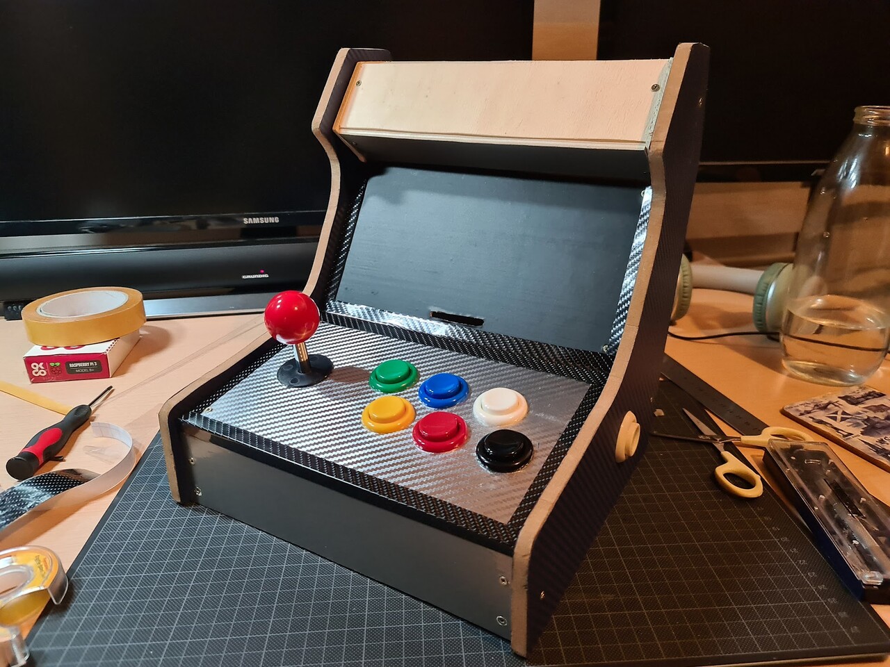
So I mounted the buttons. These buttons has a tightening ring and mounted as through hole. So they also act like a fastener for these two boards.

I ordered some carbon textured sticker foils to cover the boards. I had 3 types of foils:

Metallic Gray (for the surfaces between sides)
Black Carbon (for the corners, later I removed them)
Pain black (screen area)
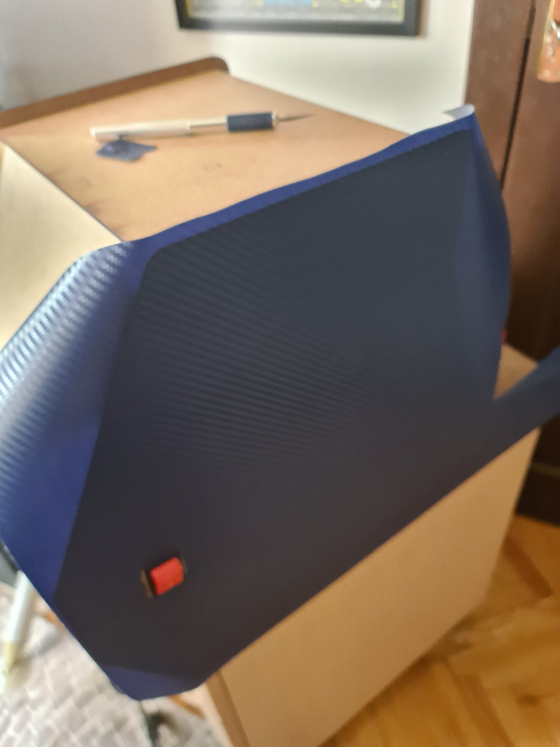
Dark Blue Carbon (sides and corners)
Metallic Carbon (for the button area)

So started applying stickers over the boards, by first unmounting them, applying sticker, then cutting the edges.

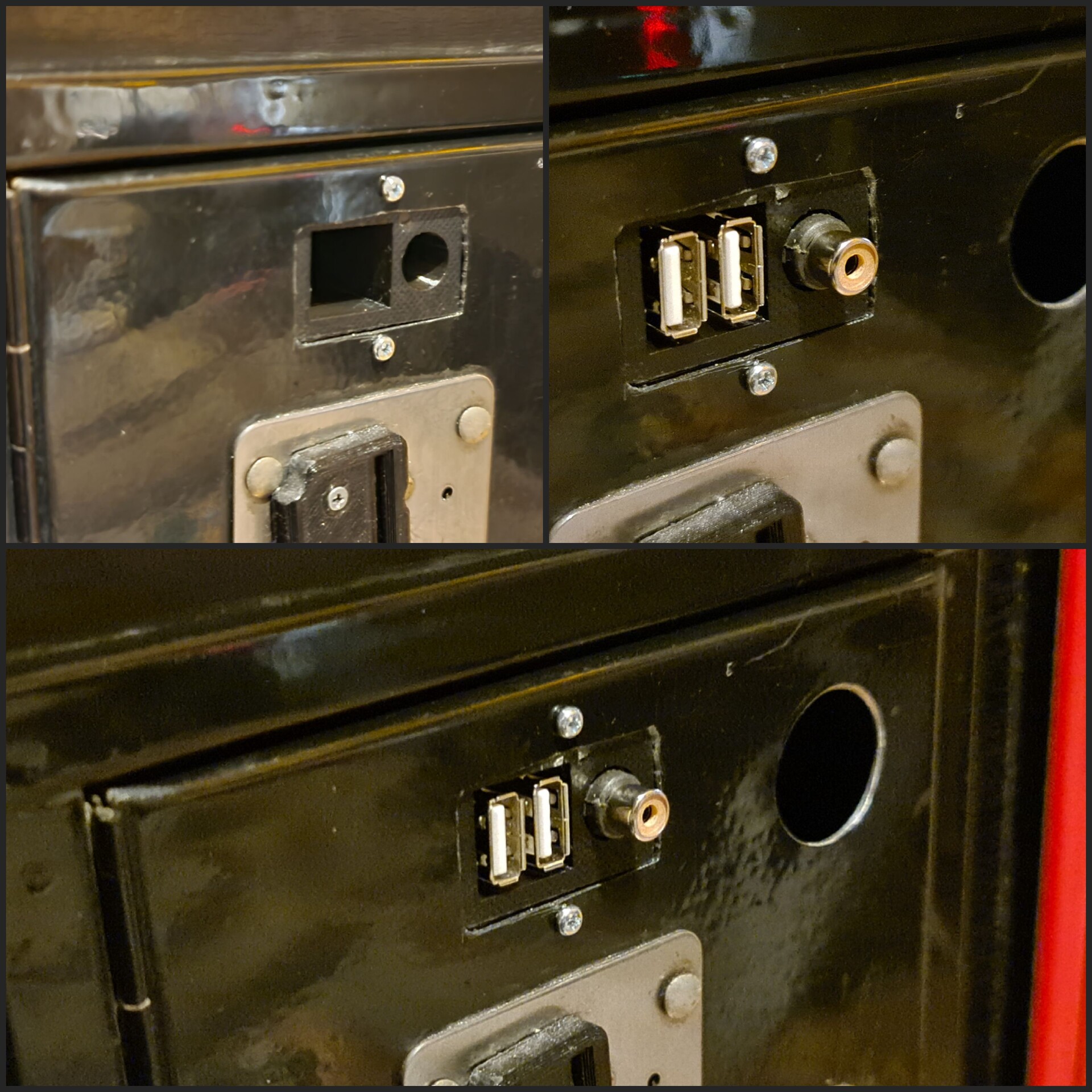
Screen and the button area are like this:

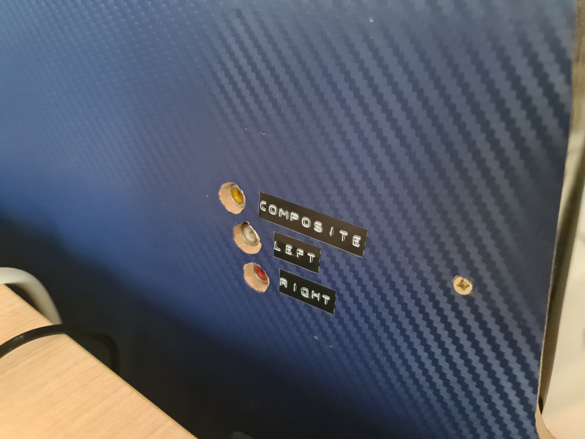
Next I covered the side edges on both inner and outer surfaces (these photos show that I only applied to the outer surfaces but later on I covered the inner surface as well). And also I used plain gray sticker for the rest of the surfaces.

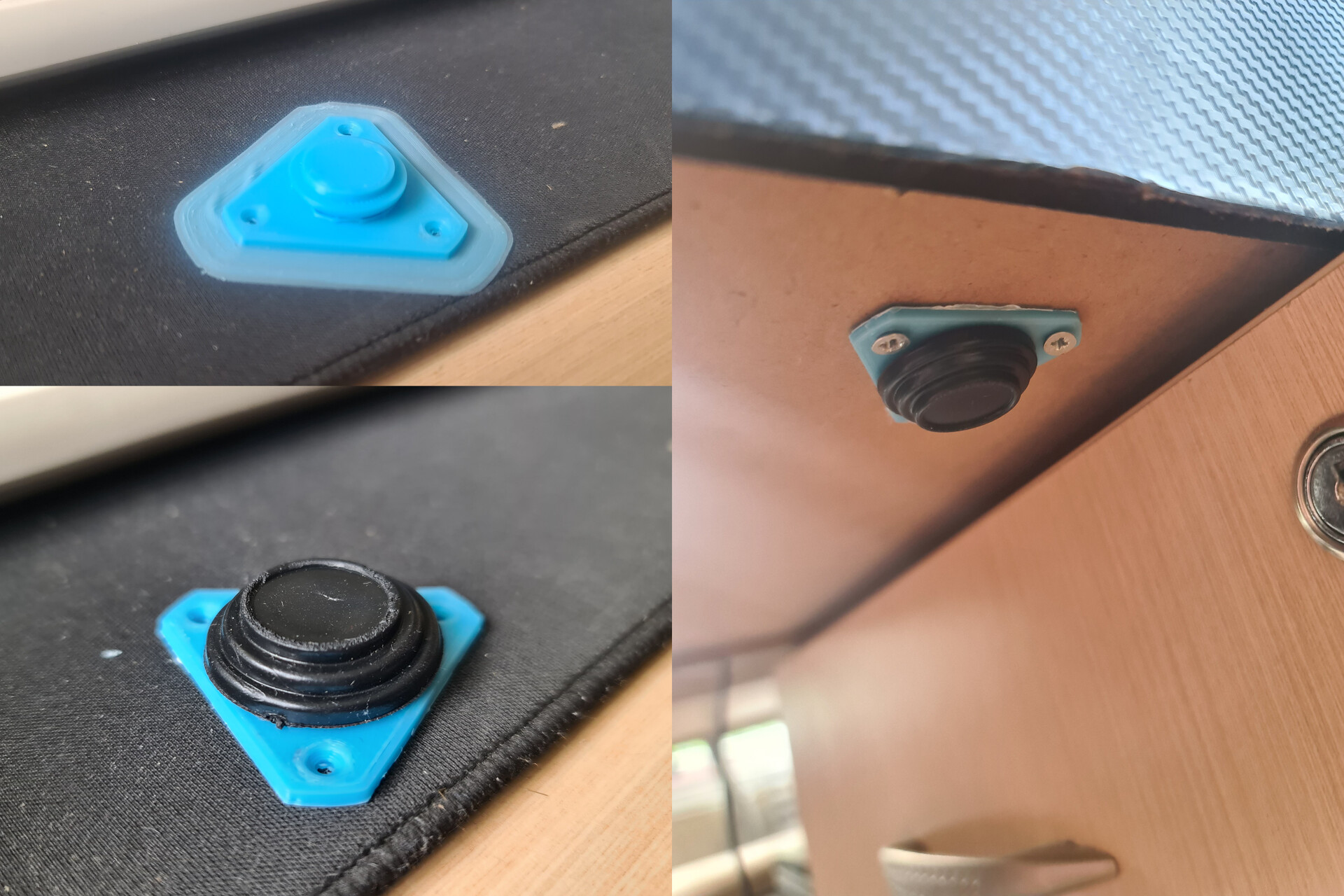
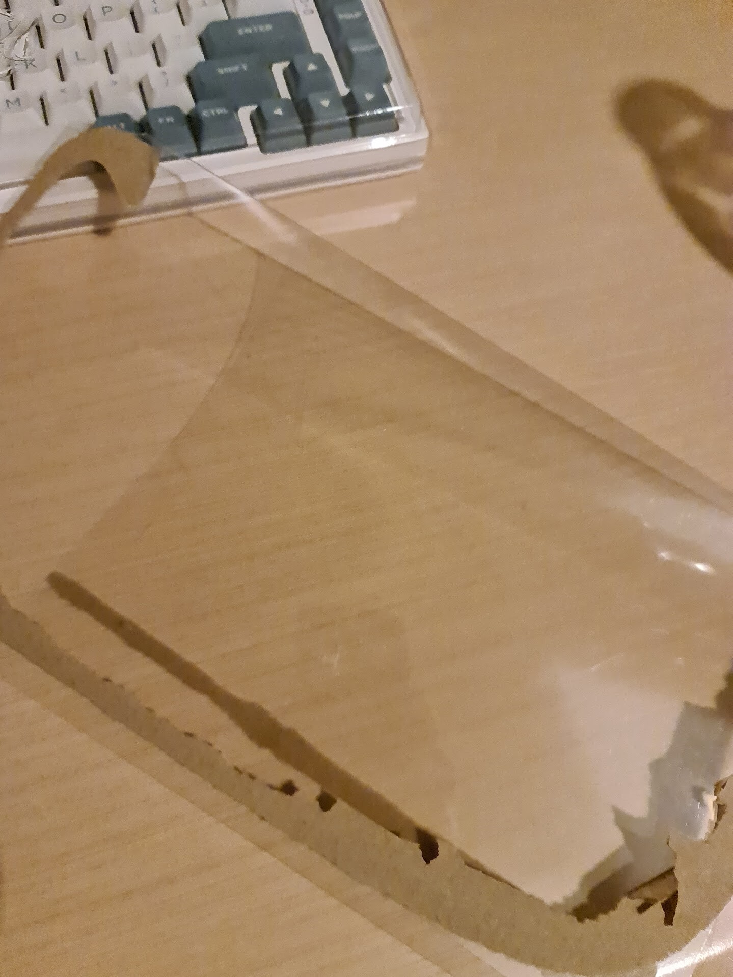
For the intersection corners, I couldn't stick a simple foil over, because it wouldn't be rigid and will be peeled. So, I made up an approach with a transparent PET sheets I have. I store this kind of transparent sheets for using on many cases like repairs, or any other developments I make using 3d printing etc. I get them from the toy packages mostly.

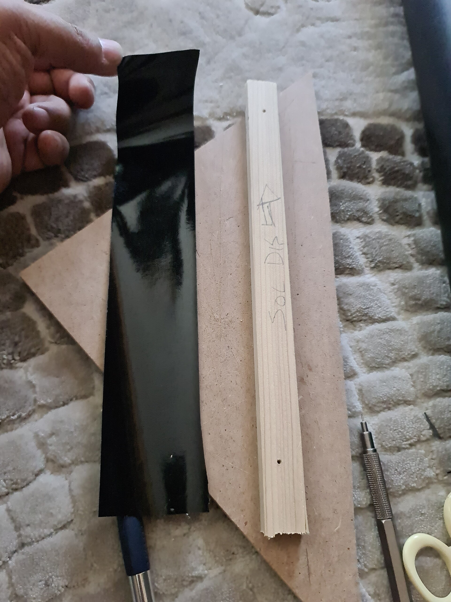
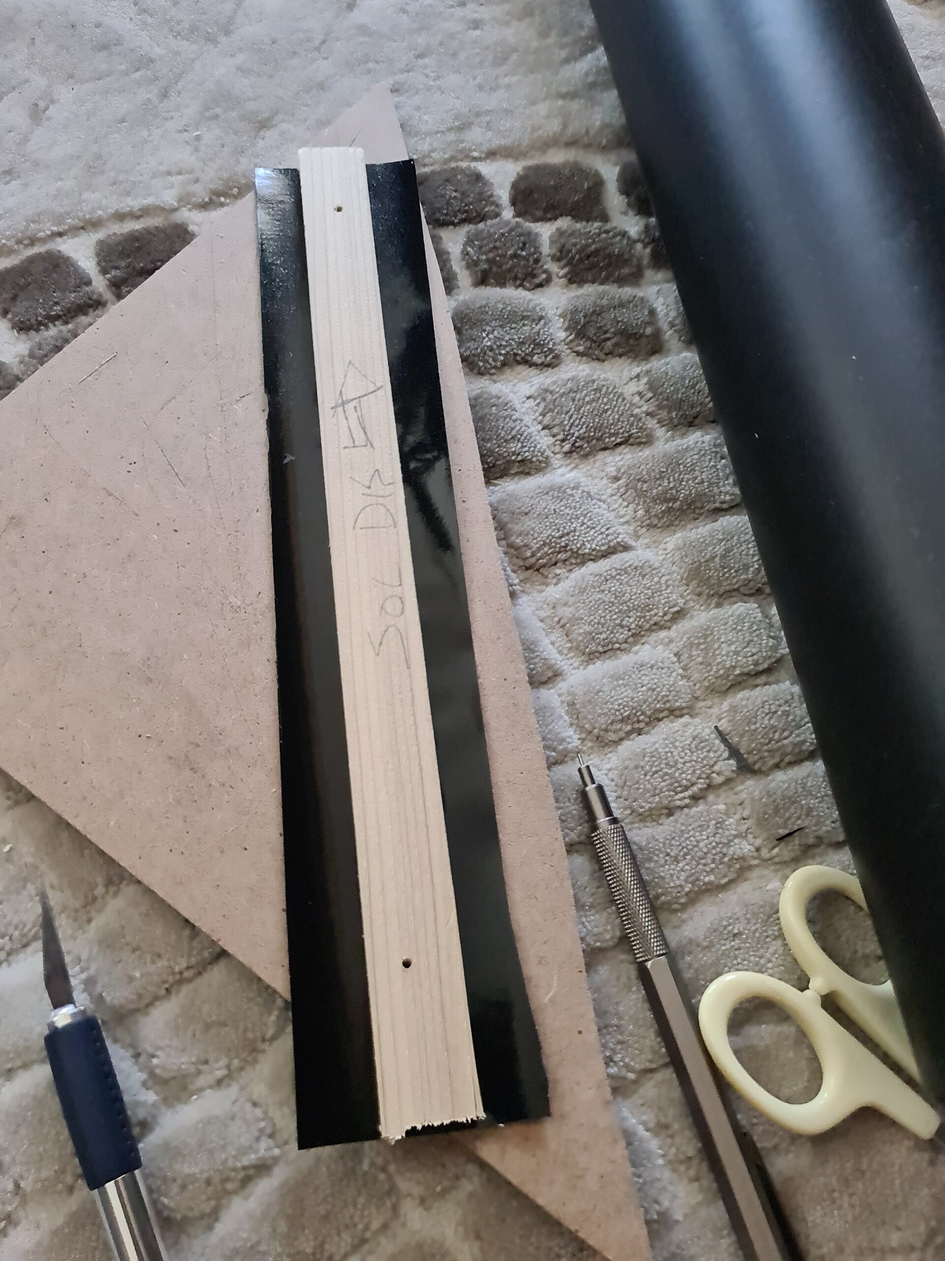
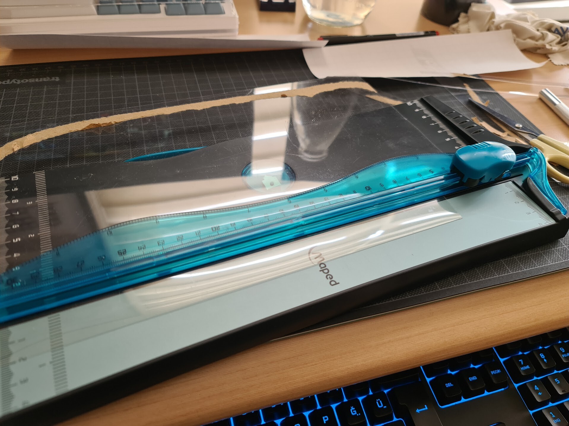
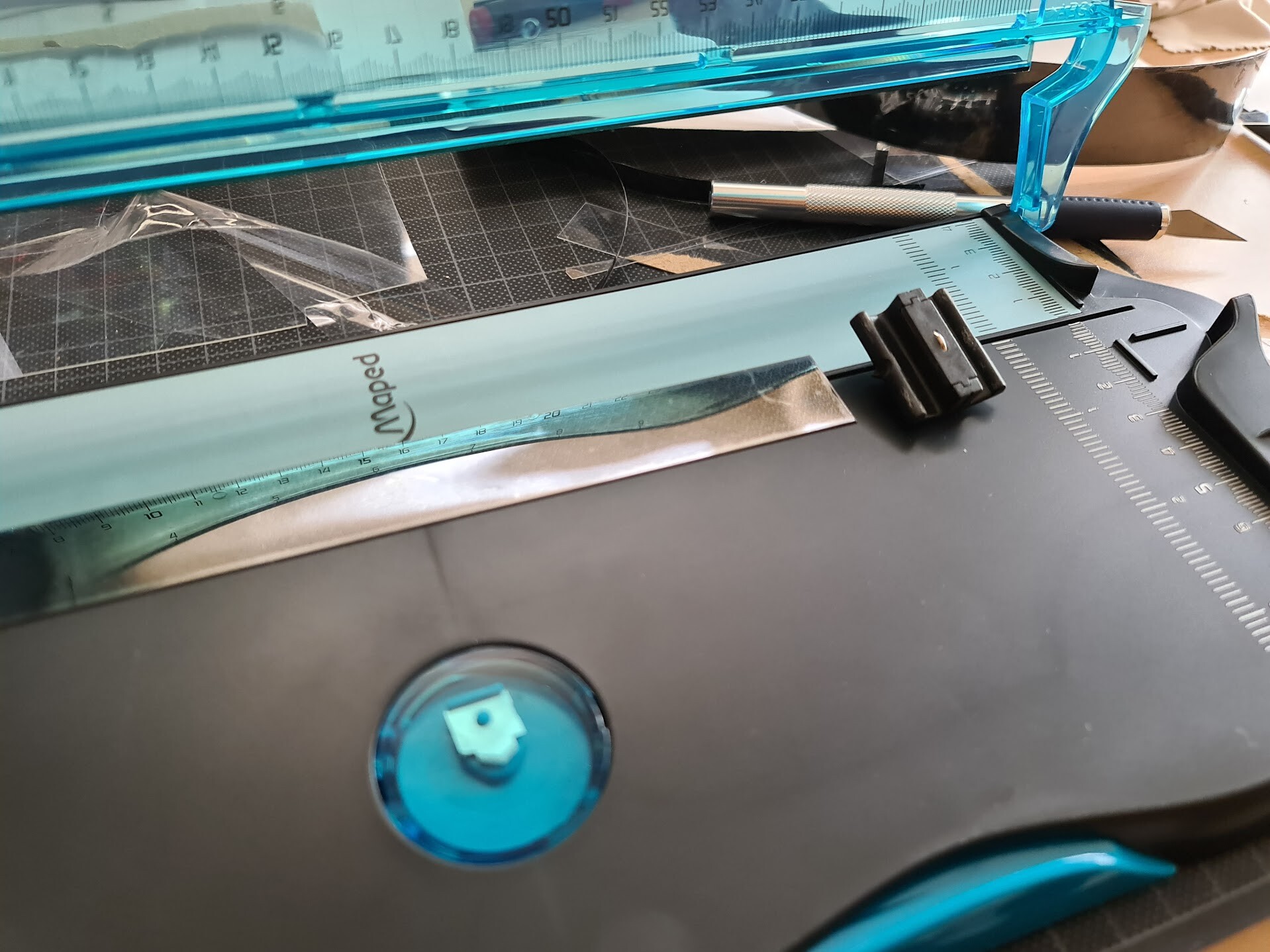
So first, I cut a stripe from the PET sheet, and I bend it. For that I had a guillotine paper cutter.

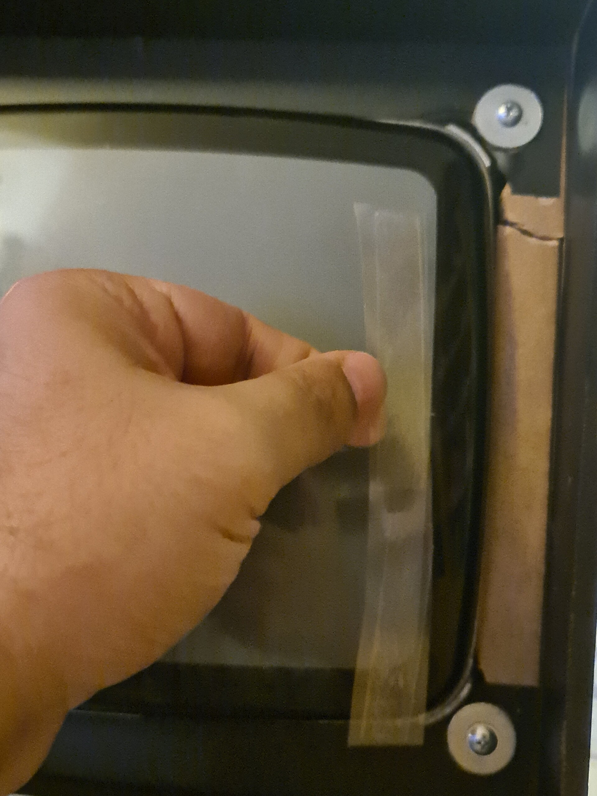
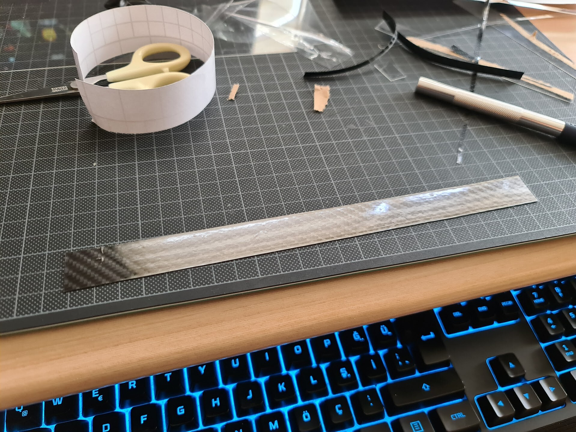
After cutting the stripe, I apply foil over it. I used black carbon foil on this one, but later on I didn't like the result and I switched to the dark blue foil instead of black. Progress is the same. Applying foil over the pet stripe makes it more durable and rigid. 

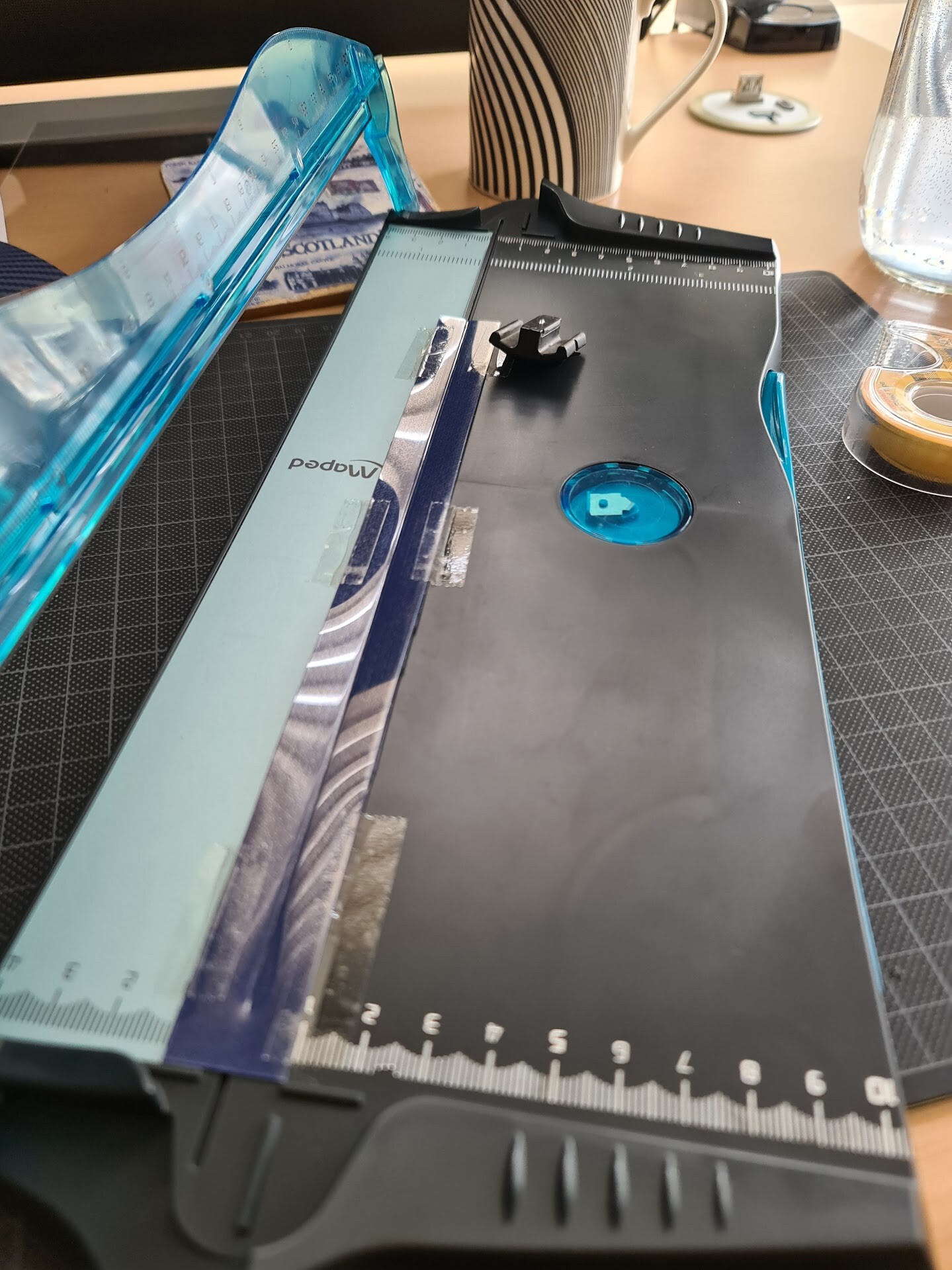
Next I placed stripe with foil to the guillotine, but this time I used the black tiny tool to squish the bending edge through the middle of the stripe. You can use any rounded and tight metal that doesn't scratch the PET but make it easy to bend through the rail of the guillotine cutter.

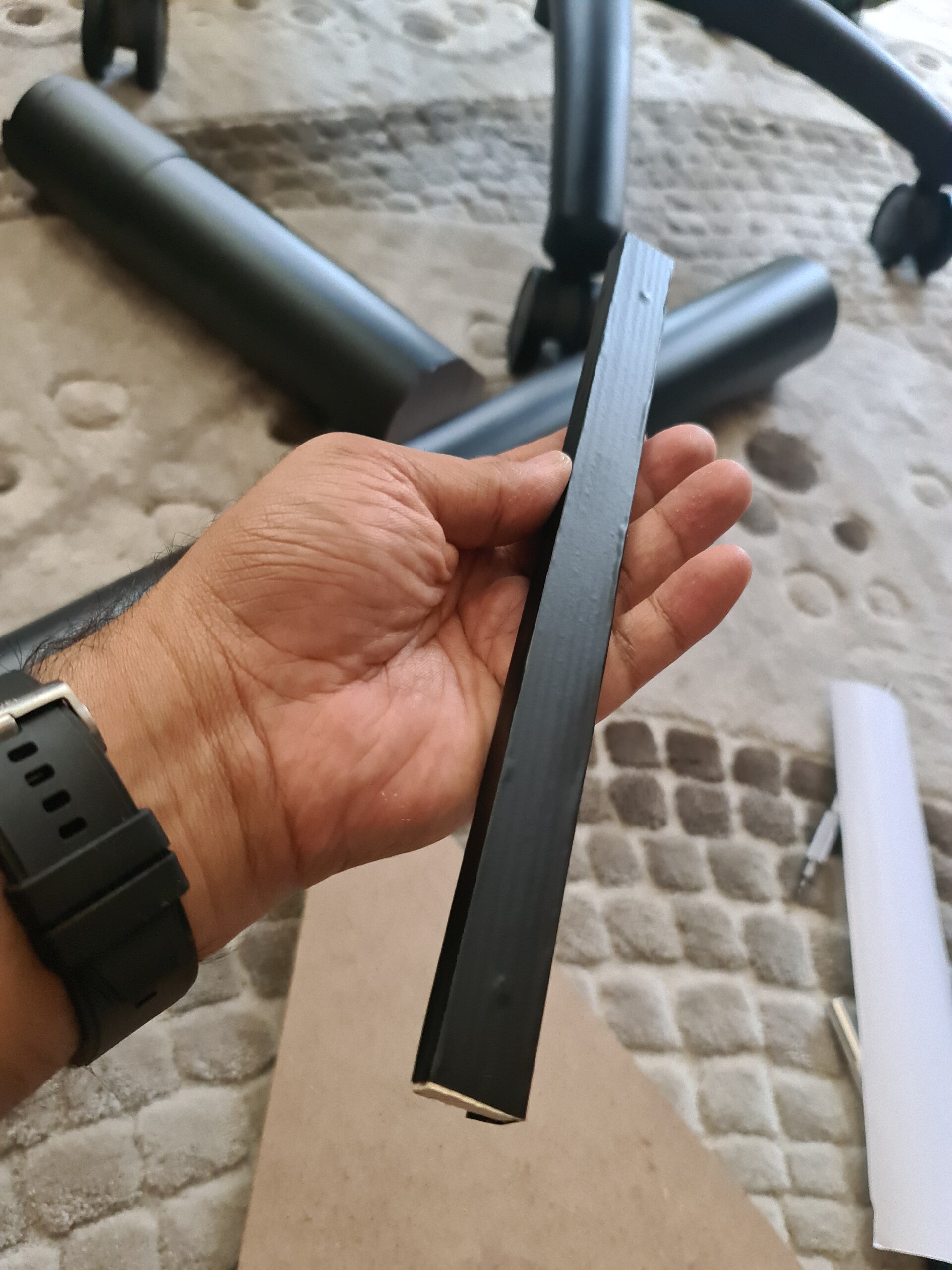
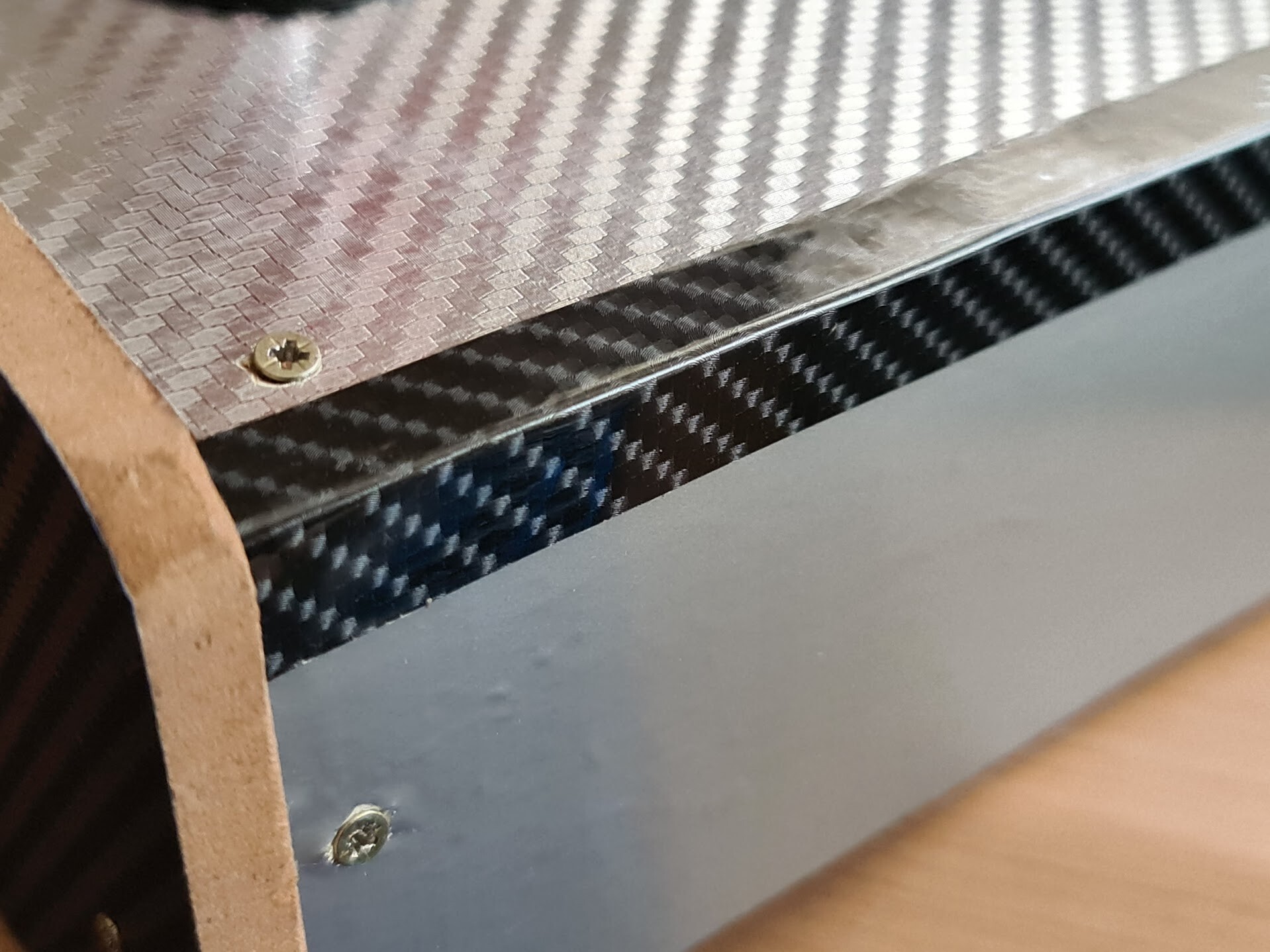
This is how the bended corner looks.


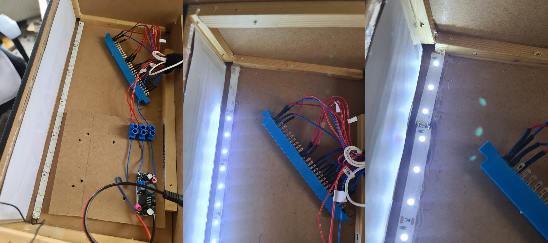
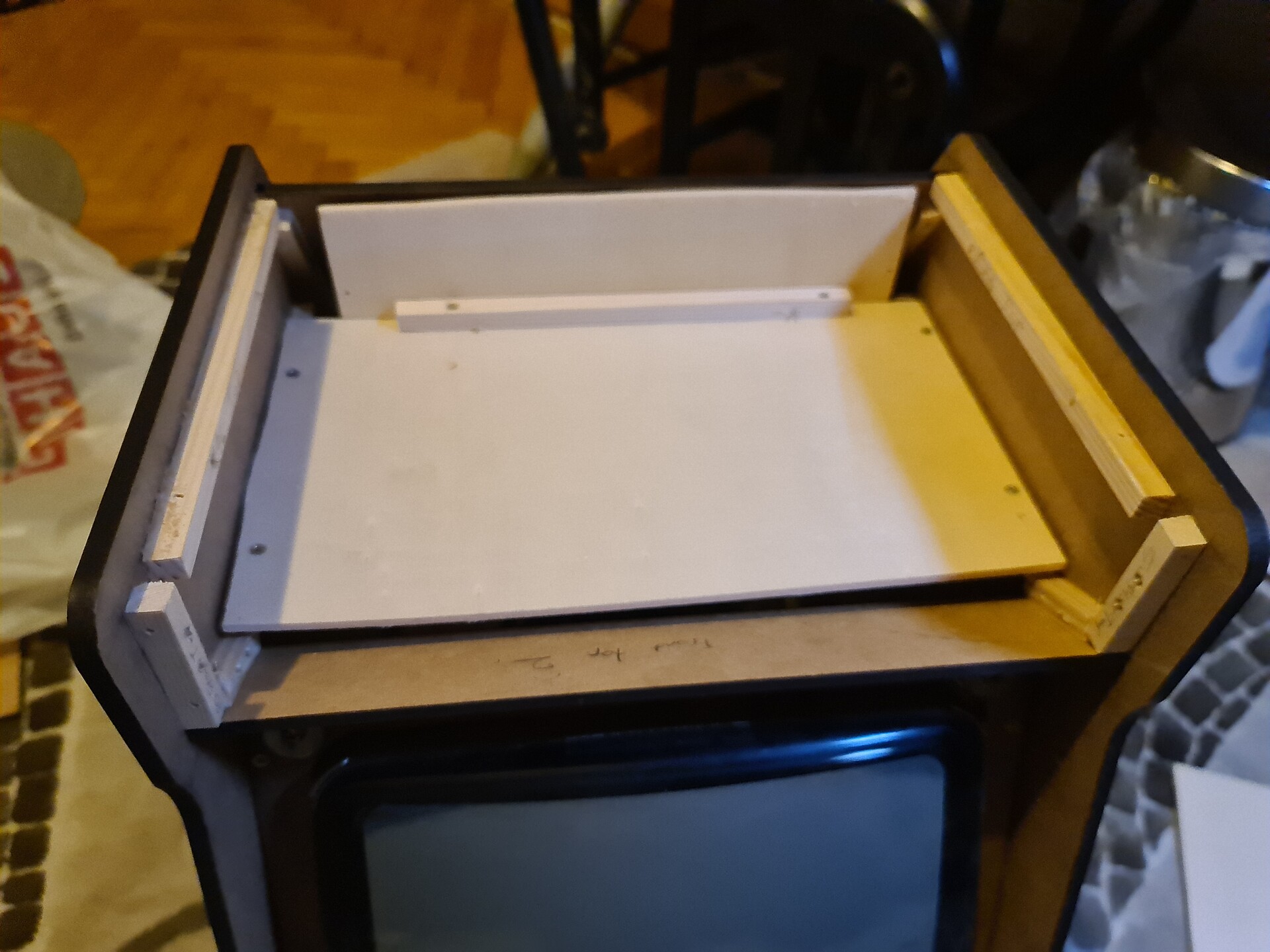
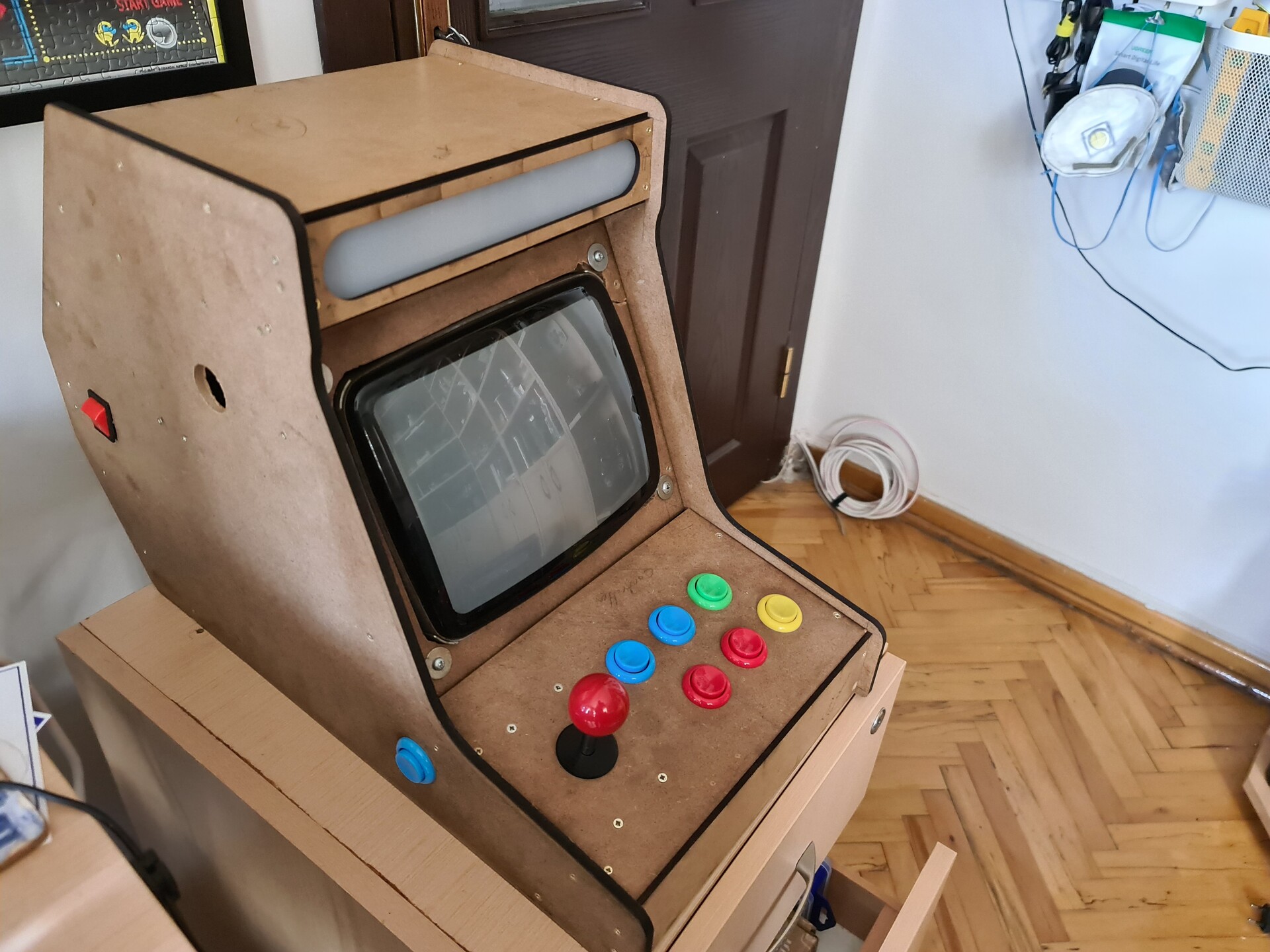
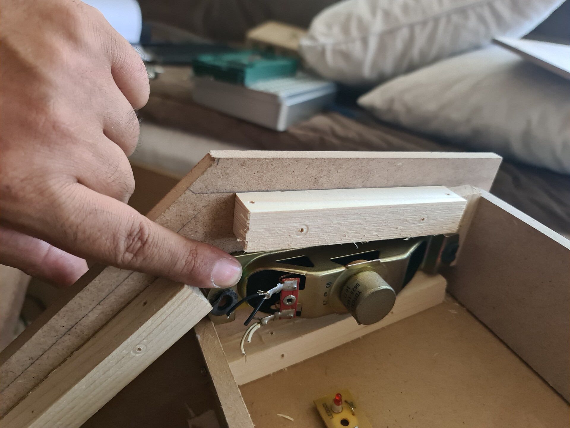
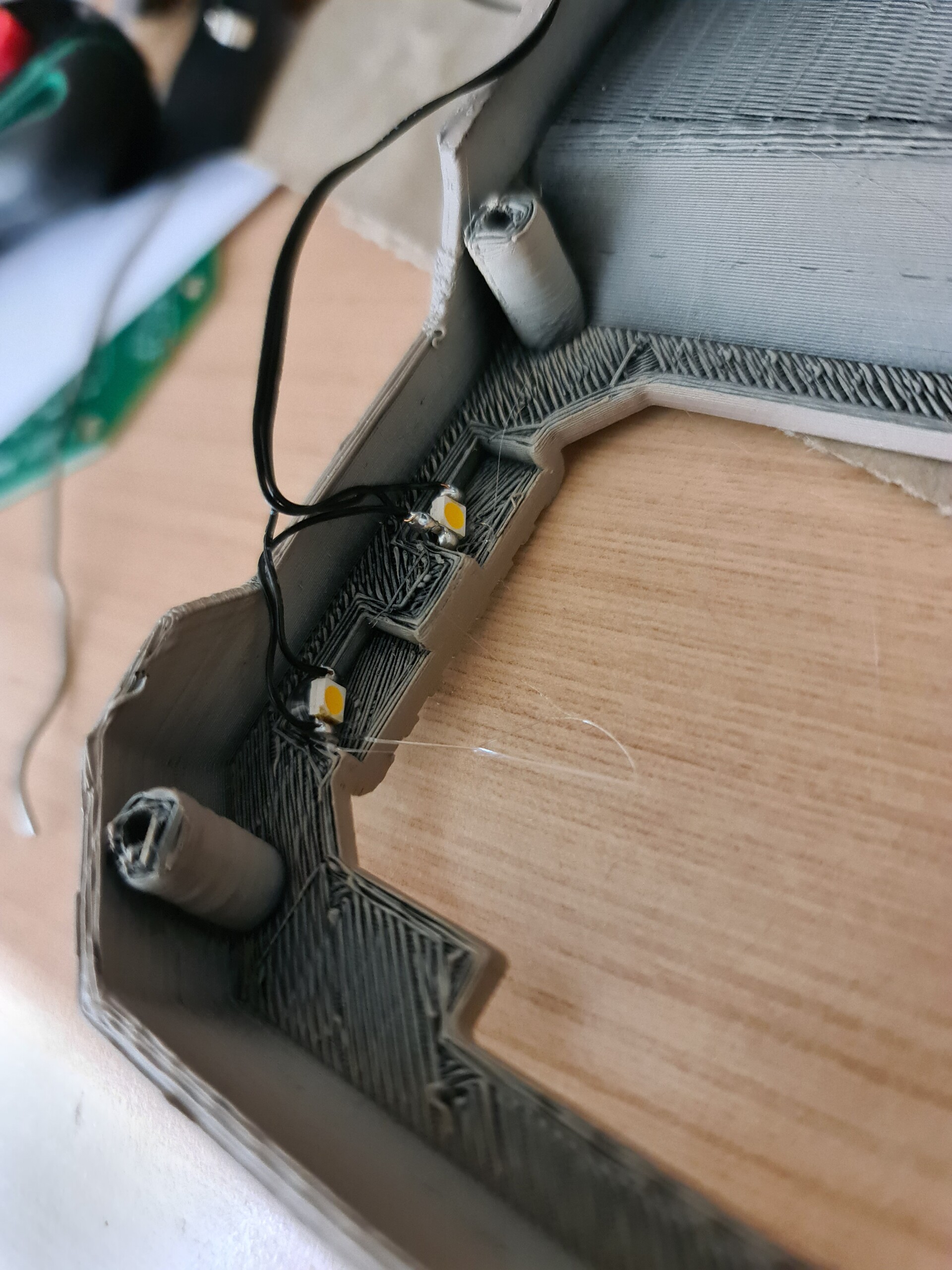
Next I mounted a LED stripe for the lighting the cabinet. This board is the G board on the part list I shared above. Then I covered it with plain gray foil and mounted back.

My lovely daughter is playing some Sonic racing game with her PS Vita back there.

As I mentioned before, I didn't like the black corner covers, so I changed them with dark blue.

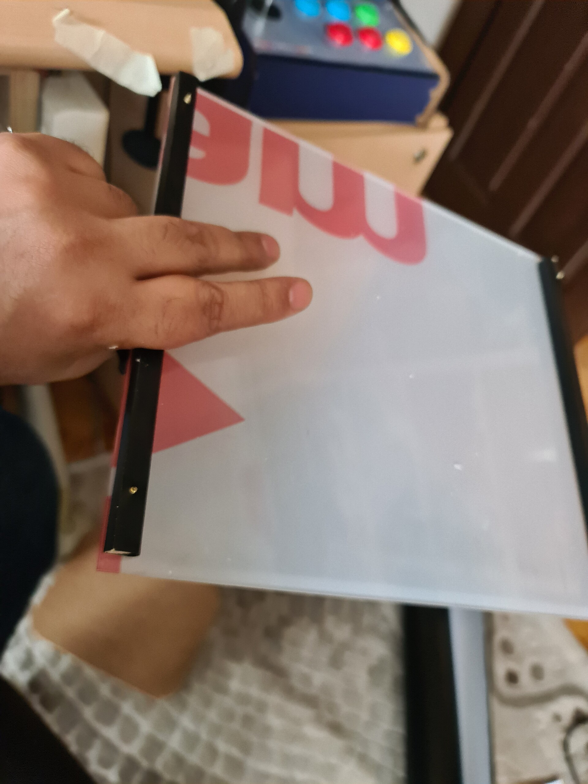
For the top lit panel, I had only frosted plexiglass at the hand. So I moved on with the frosted PG and ordered a translucent one to switch later on.

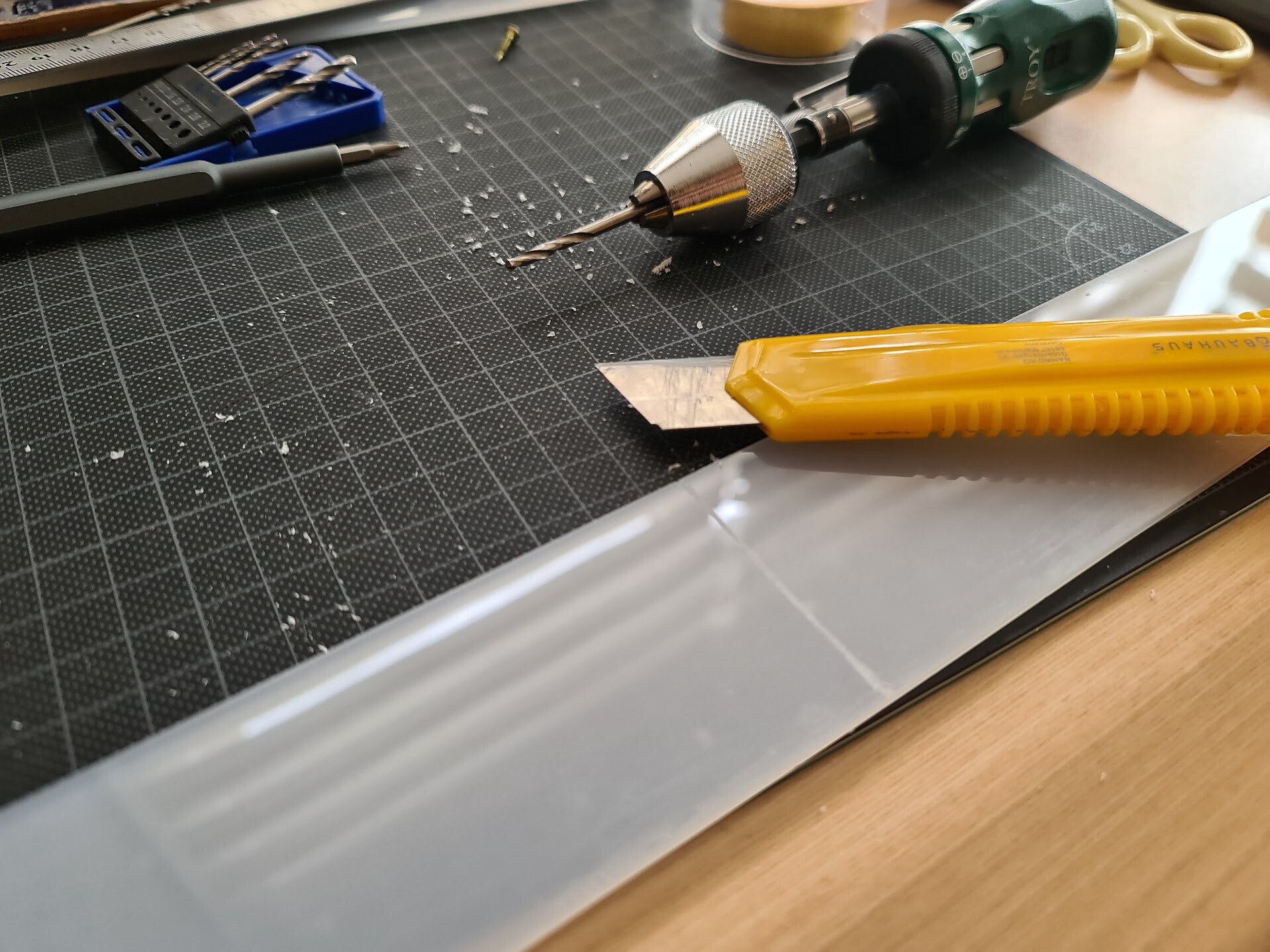
There materials are very fragile on bending without heating. But you can cut them with the back of the box cutter. You use the back of the knife 4-5 times, and bend it. So it breaks through the scratched line.

I drilled the holes and mounted it first. I will use corner covers, so it's not important that there is a clearence at the edges.

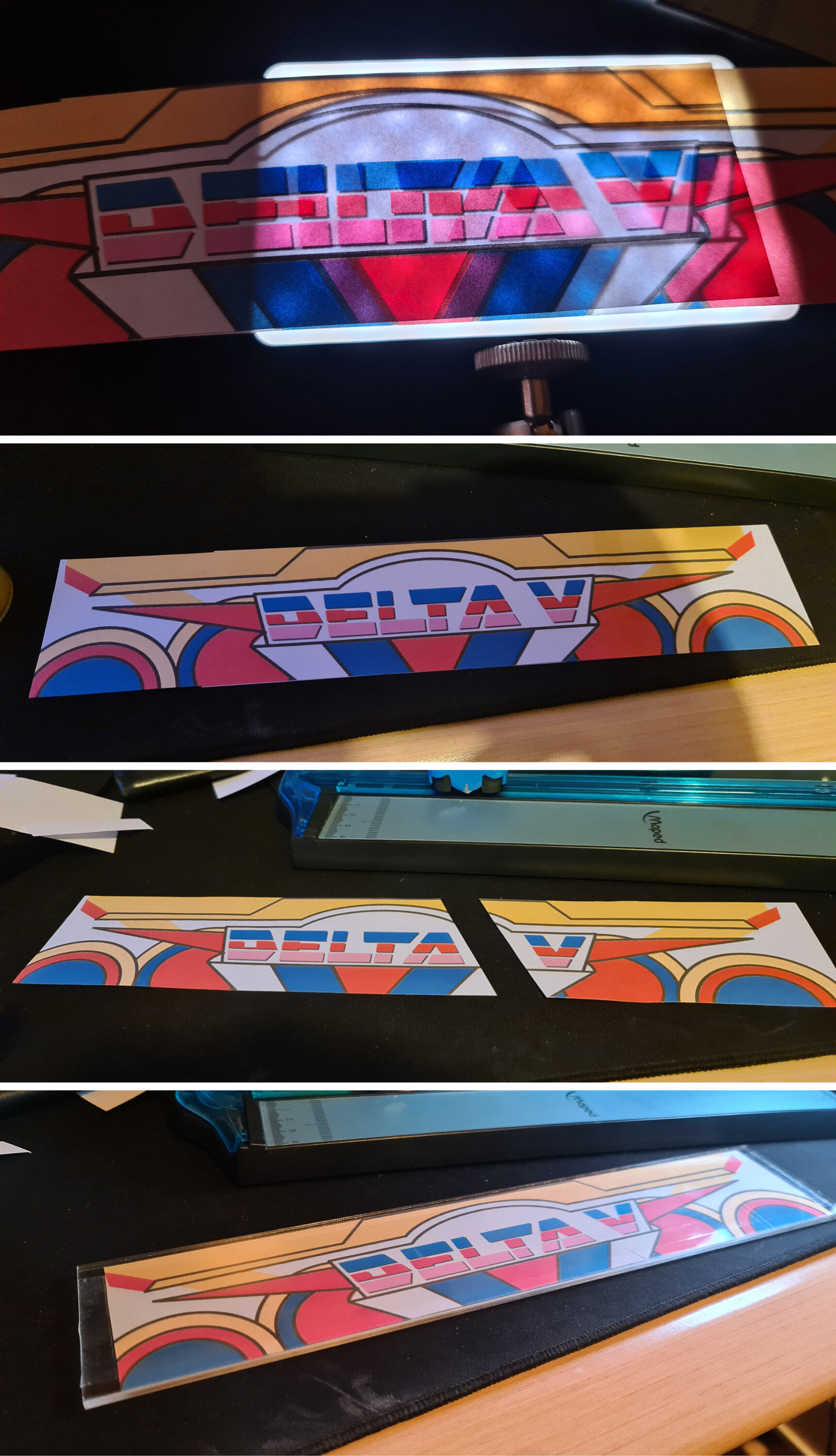
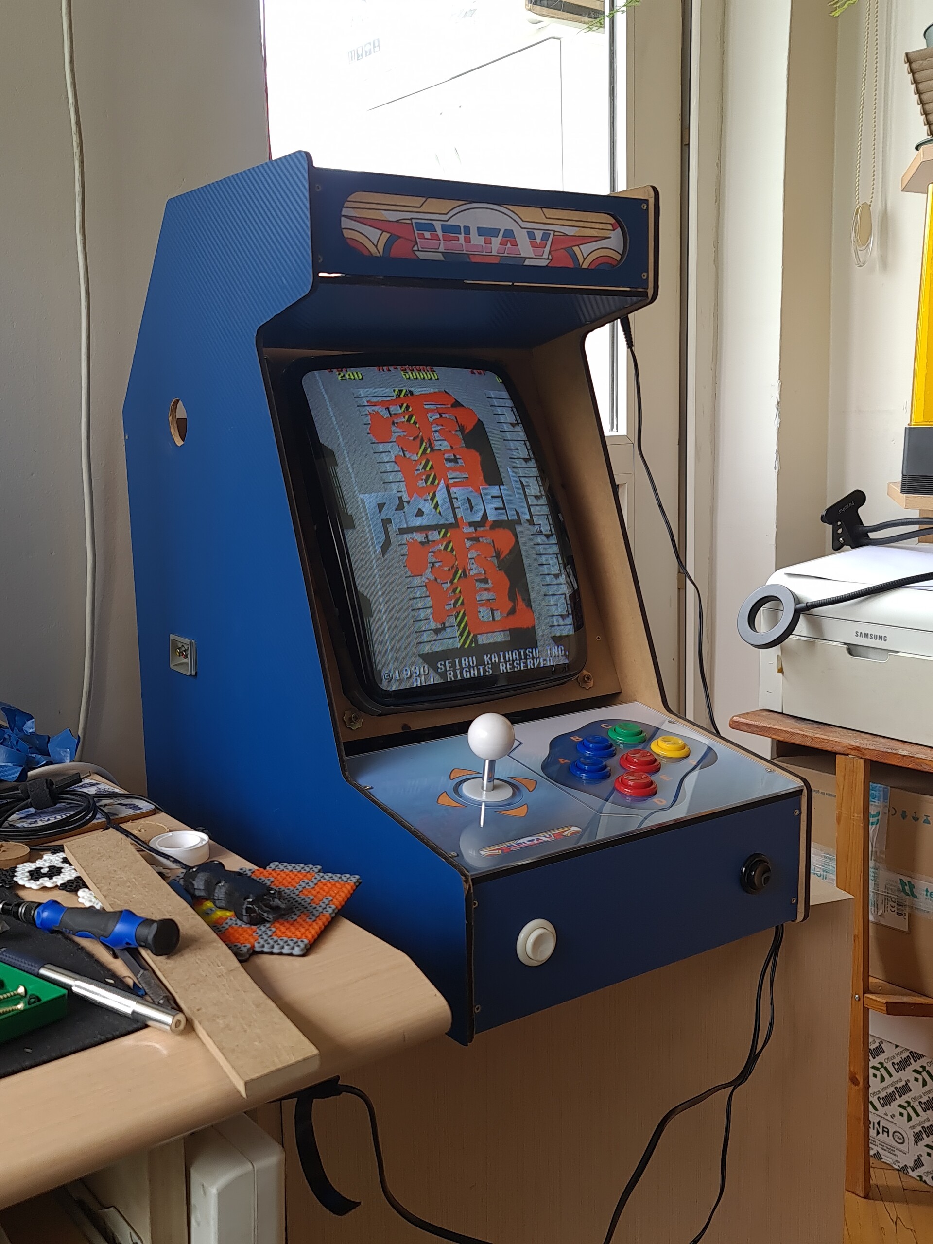
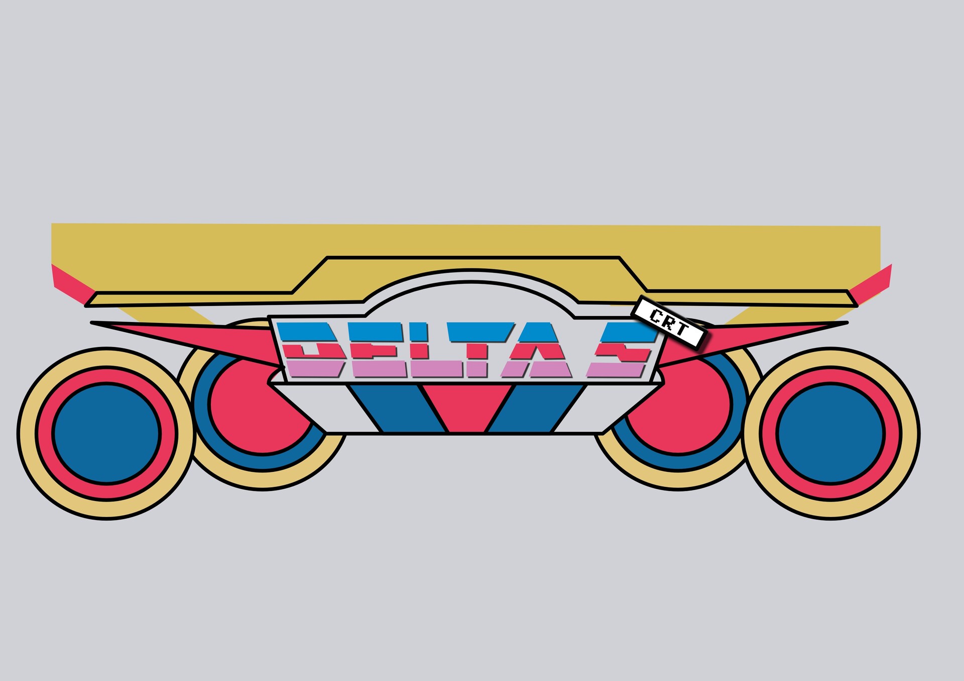
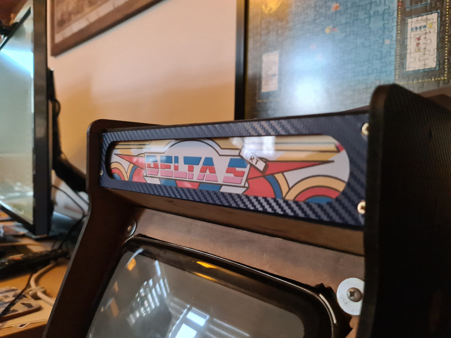
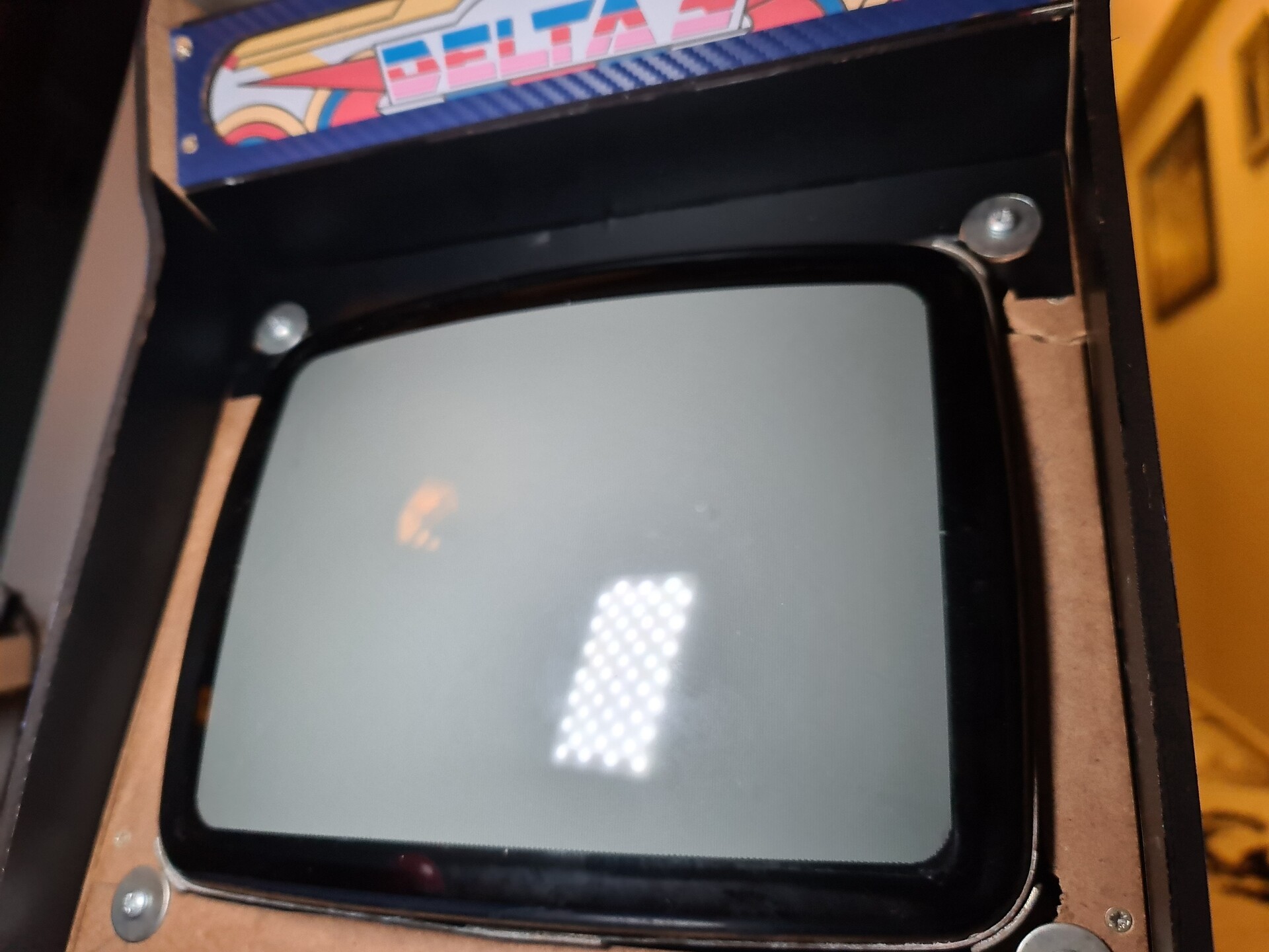
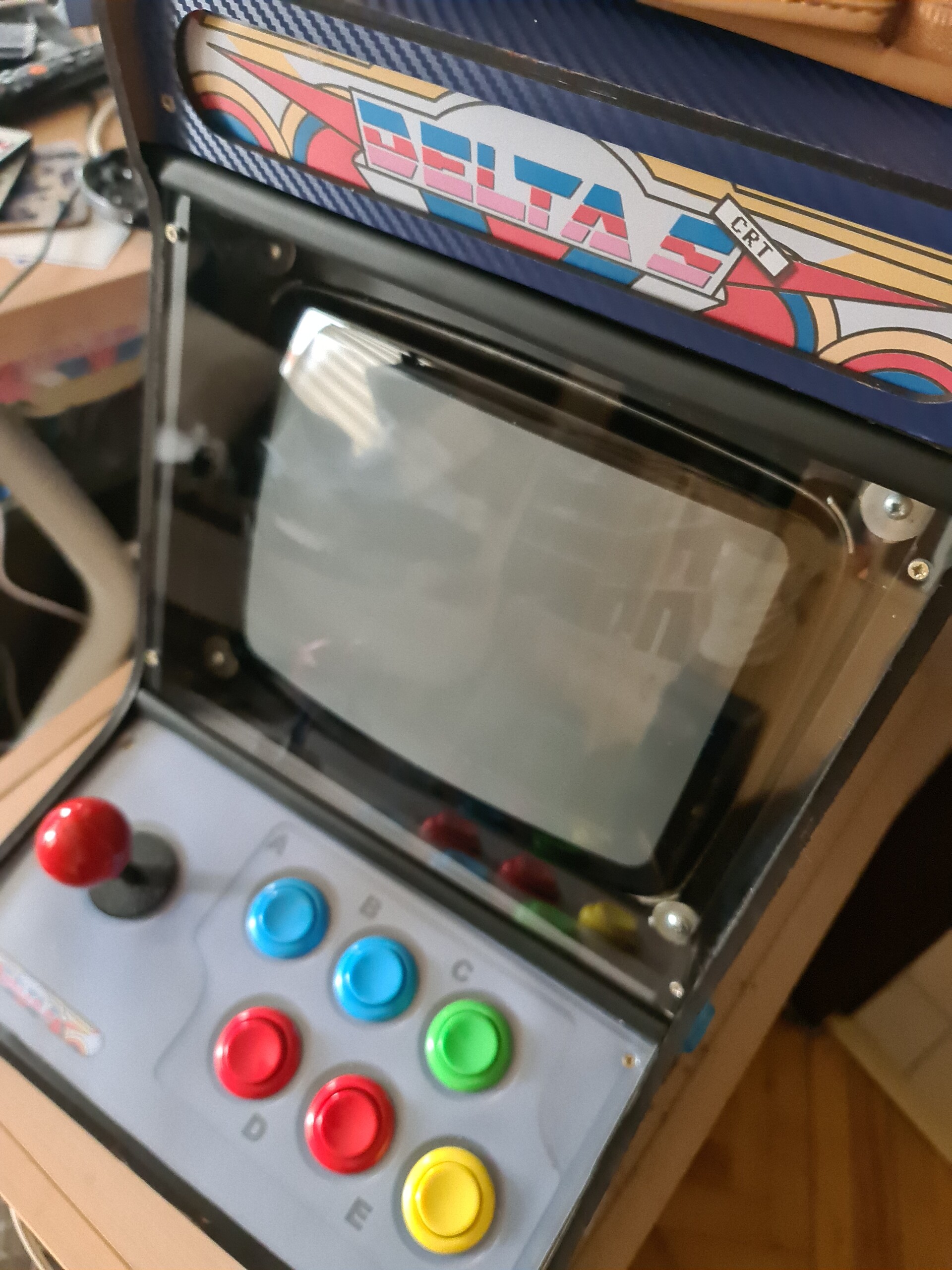
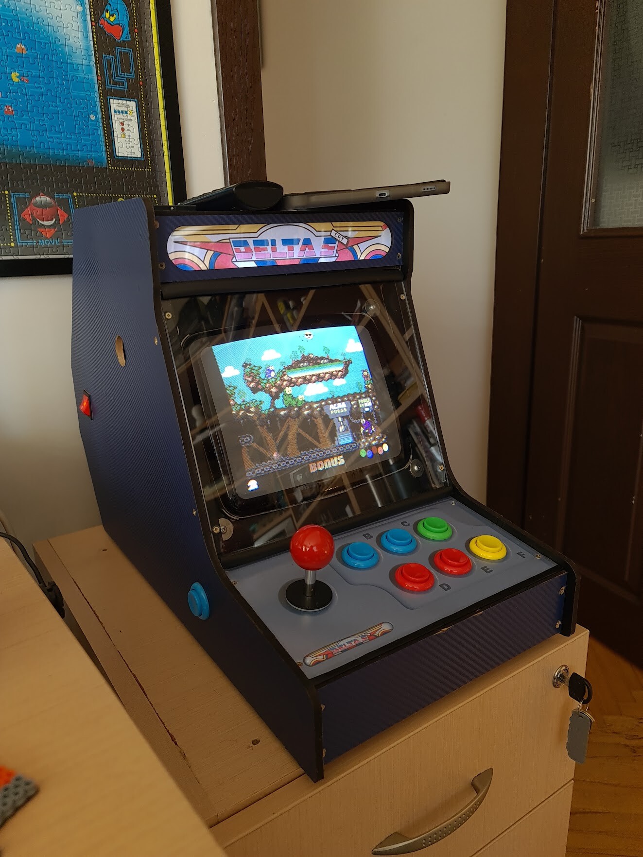
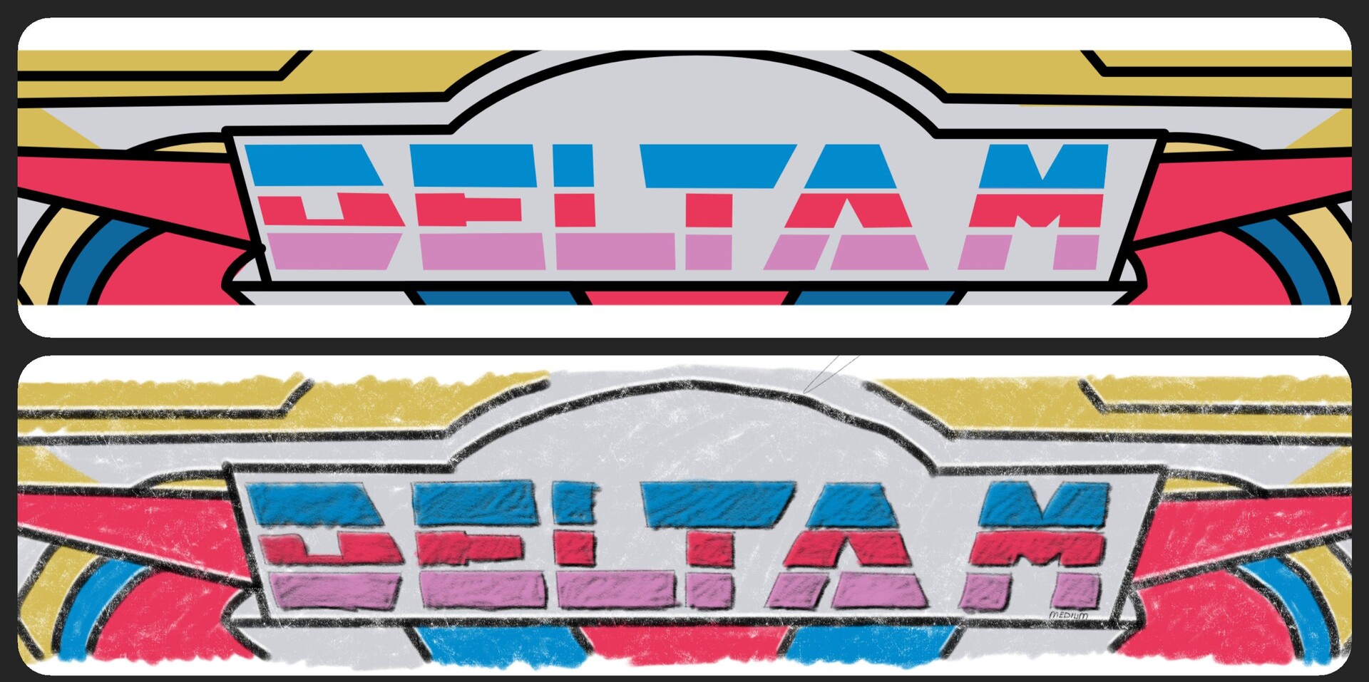
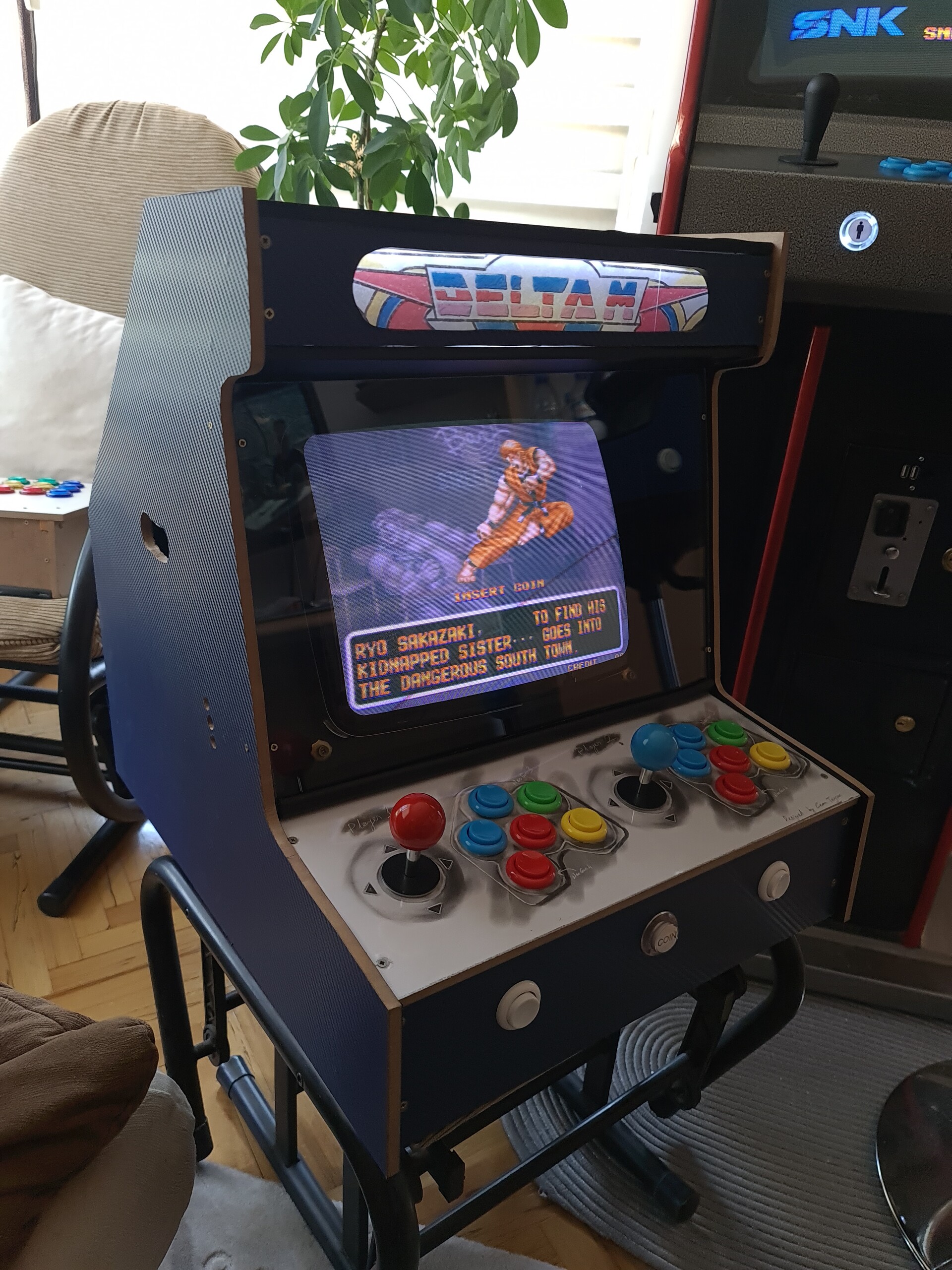
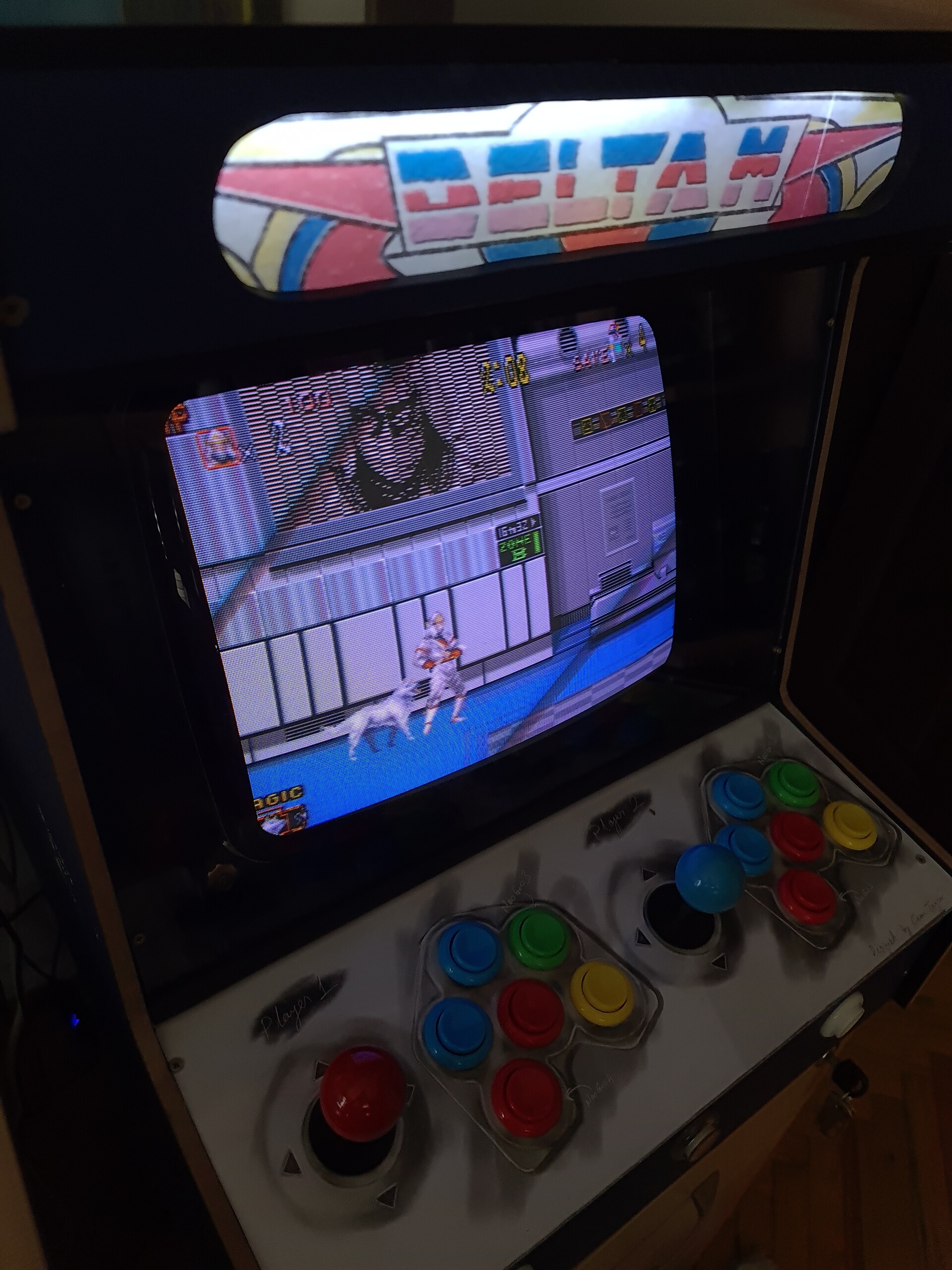
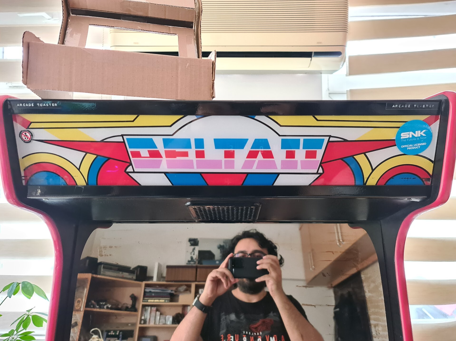
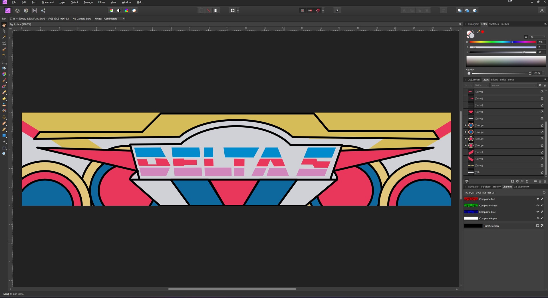
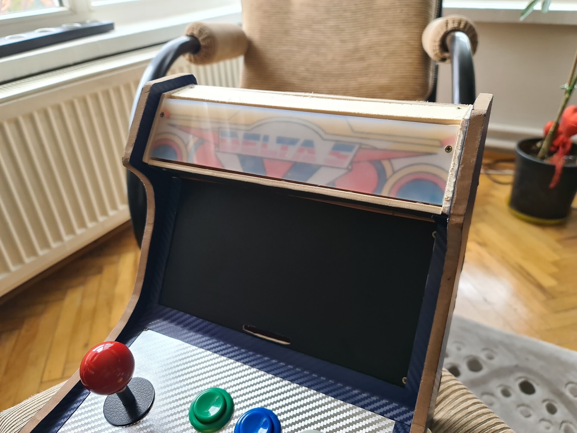
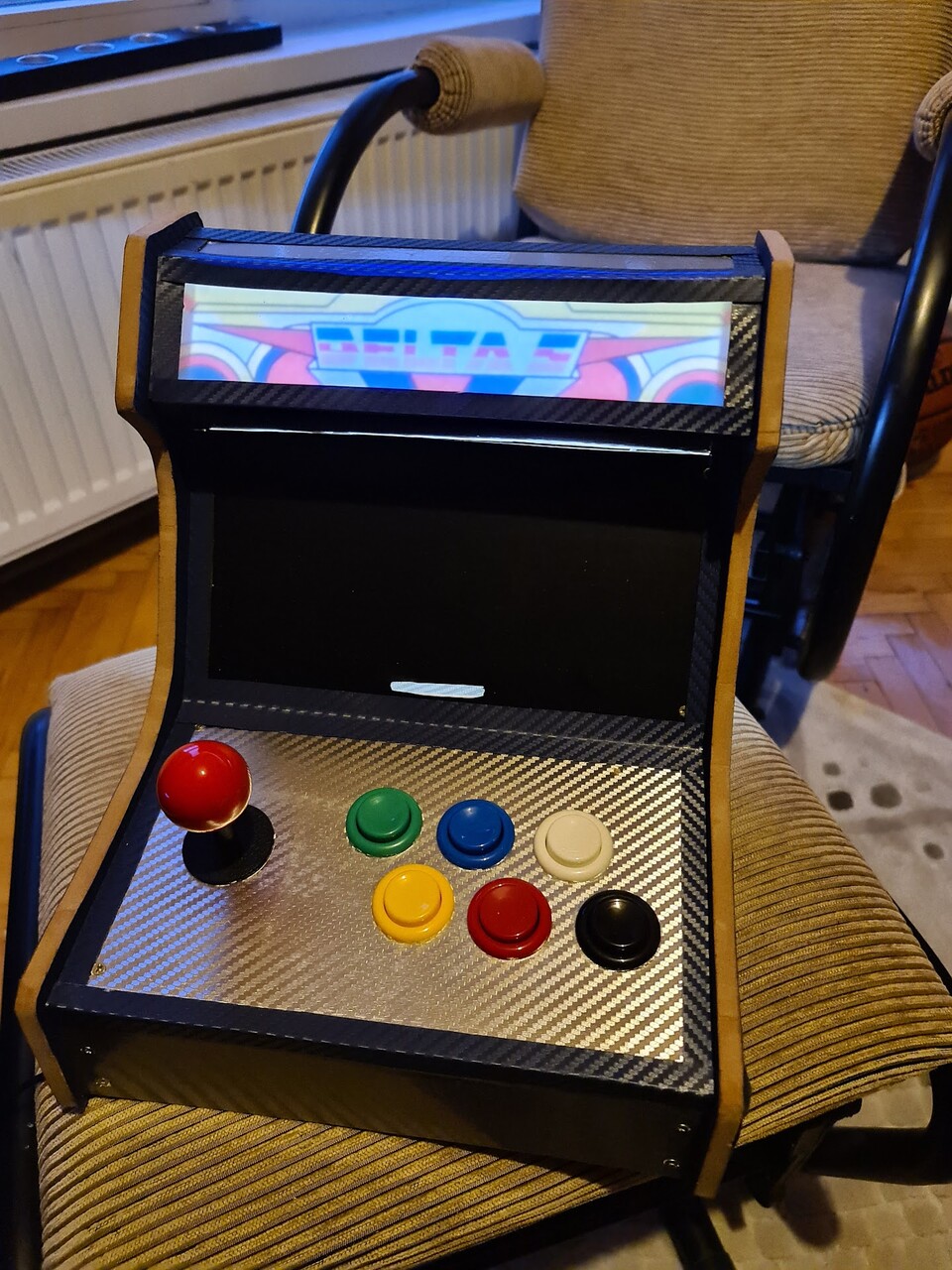
So the following part is the graphic design for the lit panel. As you know from the previous blog post, I bought an old school cabinet, which is named as "Delta II". I decided to move on with the same name with this one by naming it as Delta S. S is for "small".

I took the photo of the existing cabinet and recreated the same design in Affinity Photo.

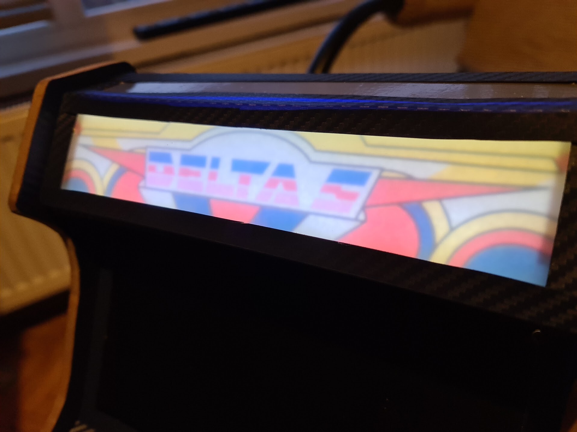
"Delta S" looks more like "Delta 5" but I can live with that :)

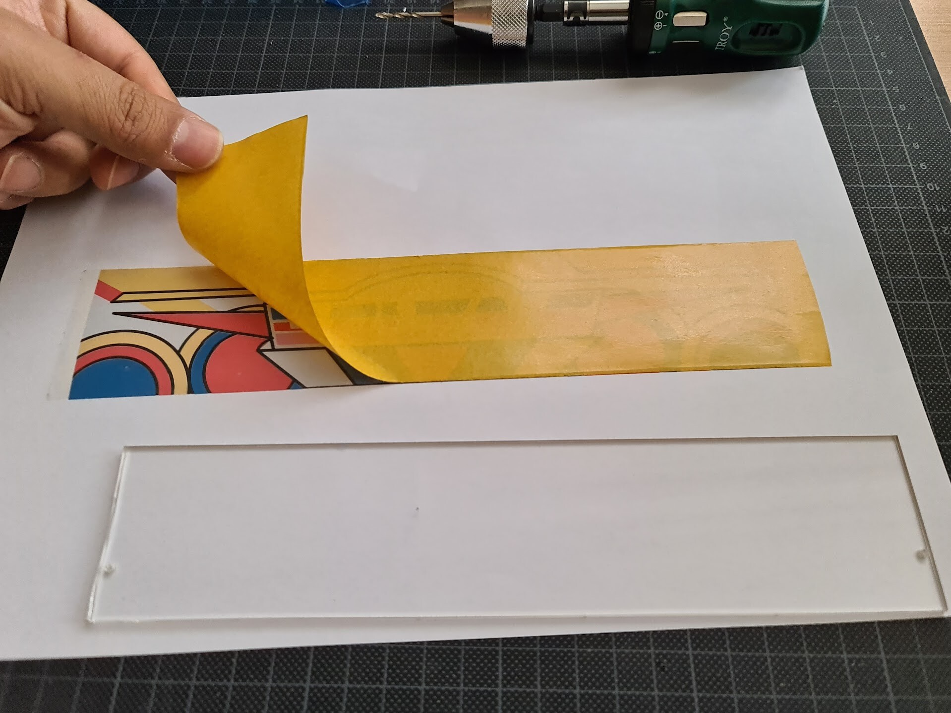
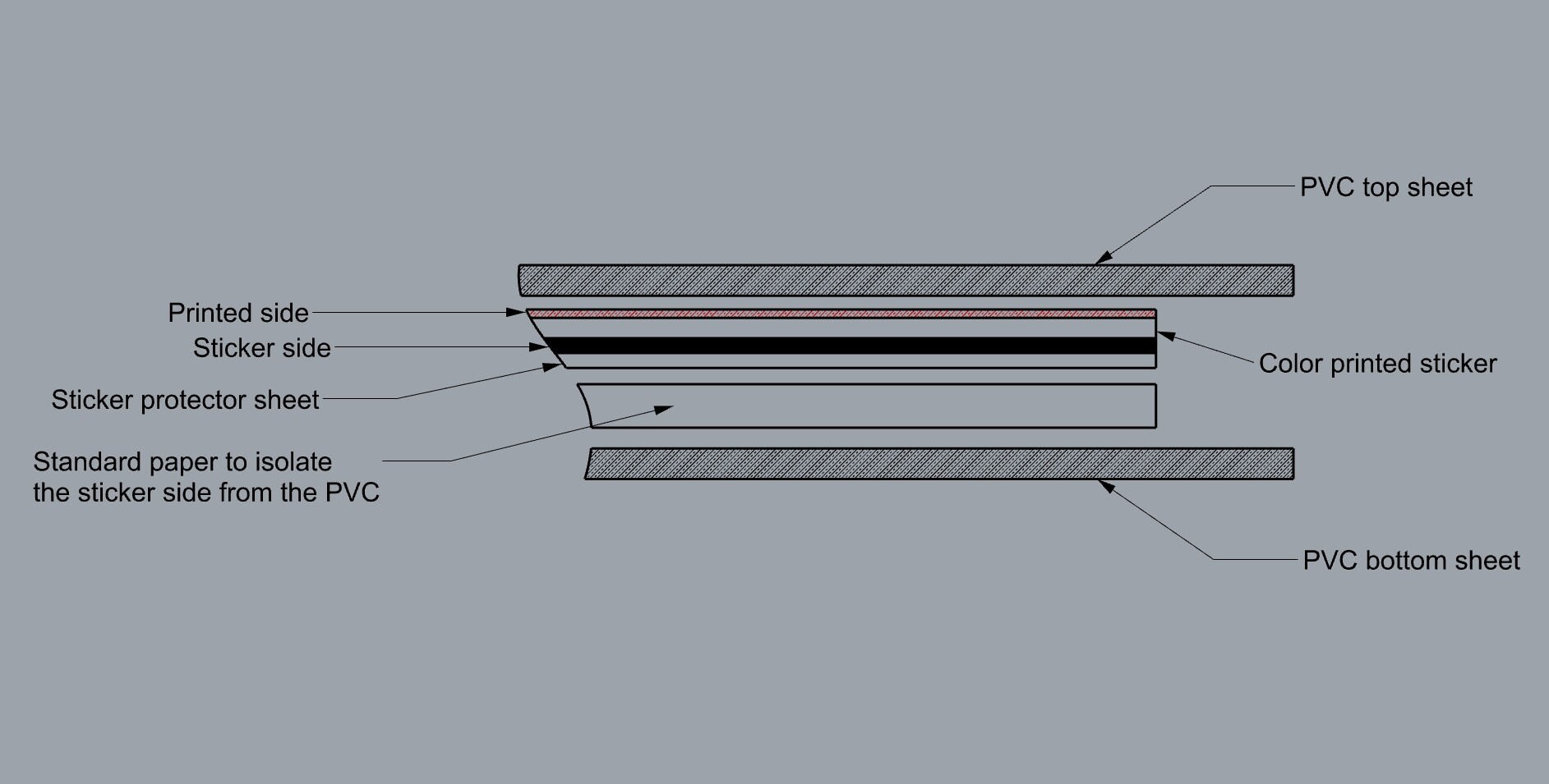
I used 2 sided tape to stick the printing to the plexiglass. These photos shows the application on the translucent PG not the frosted one, but process is the same.

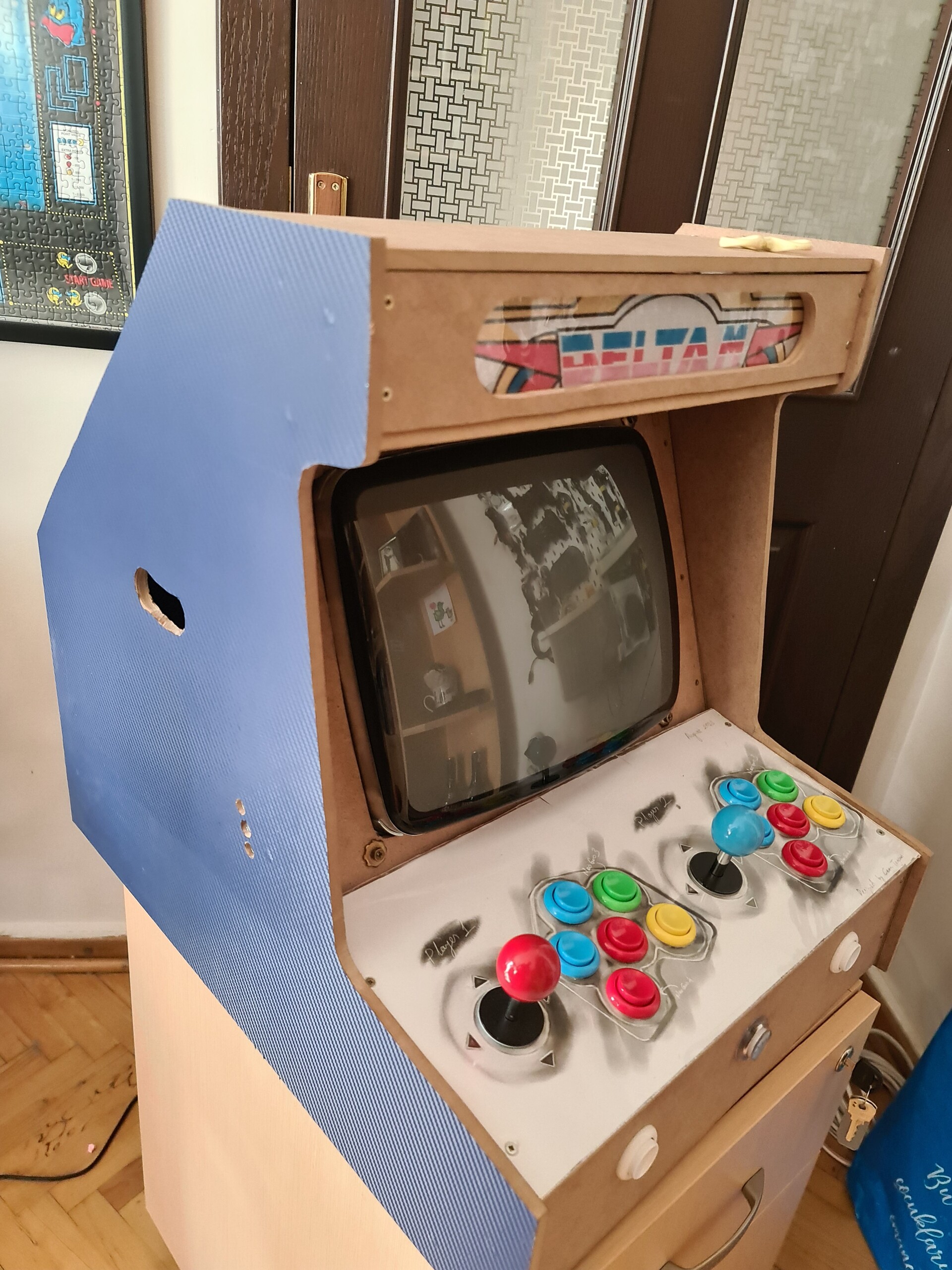
So I applied the one with the frosted PG and looks nice but blurry which I will solve on later stages when my clear glass PG is arrived.

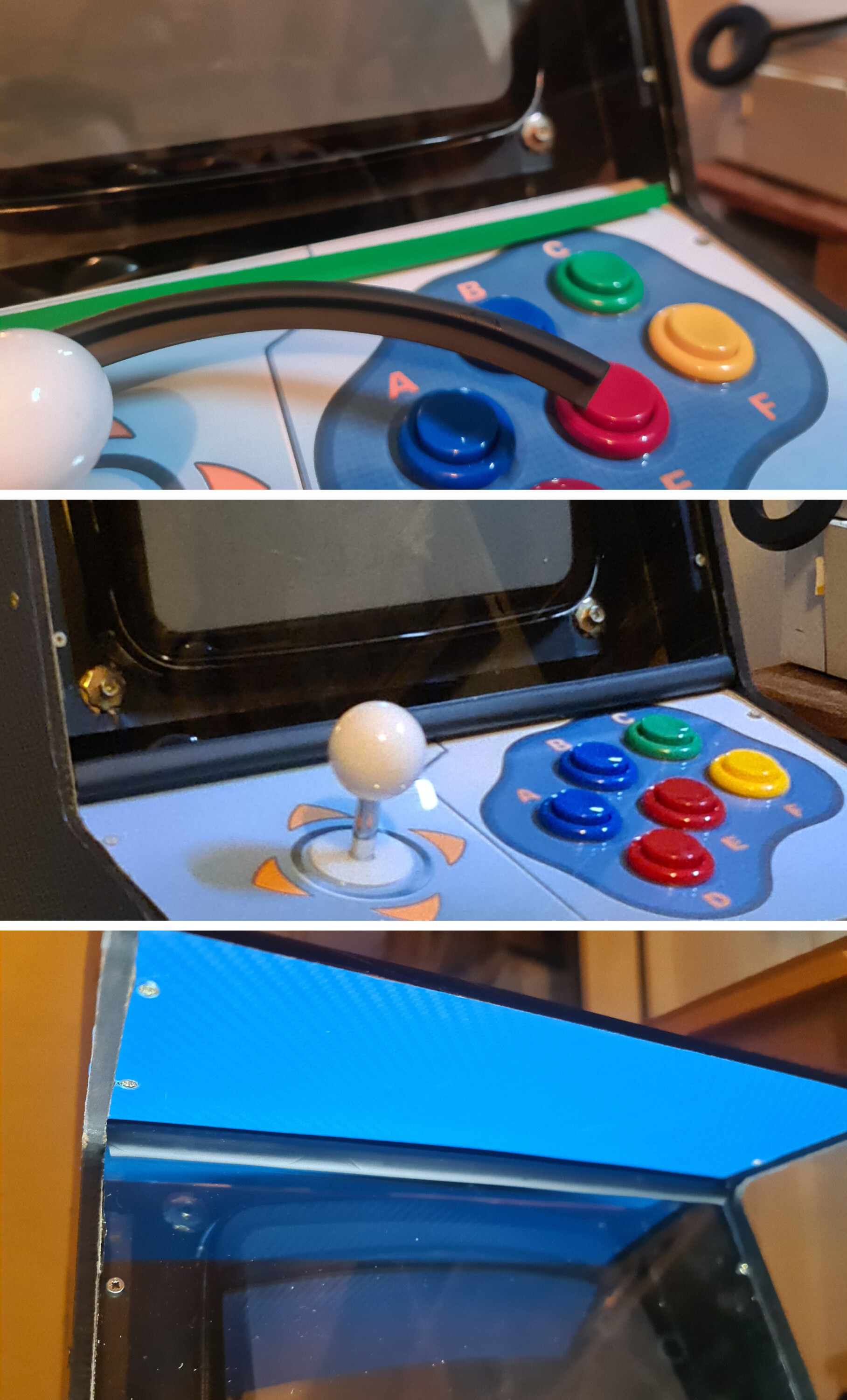
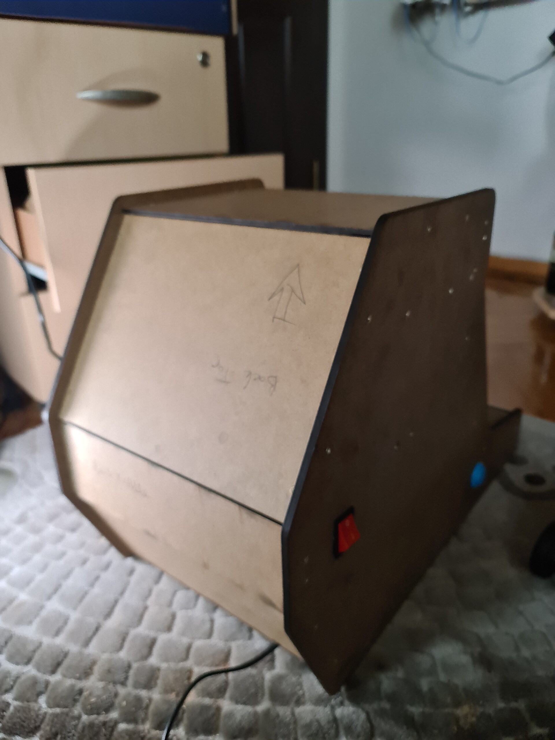
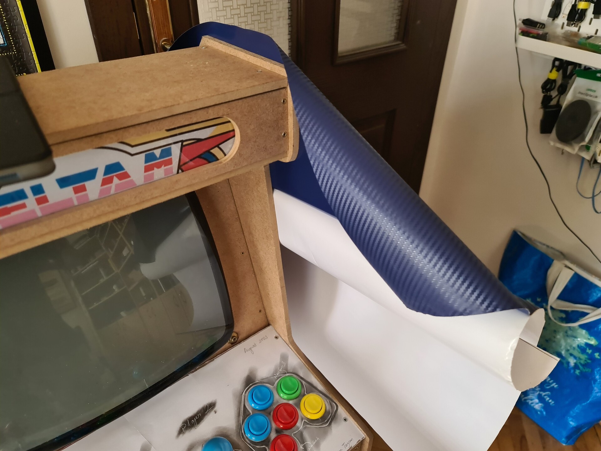
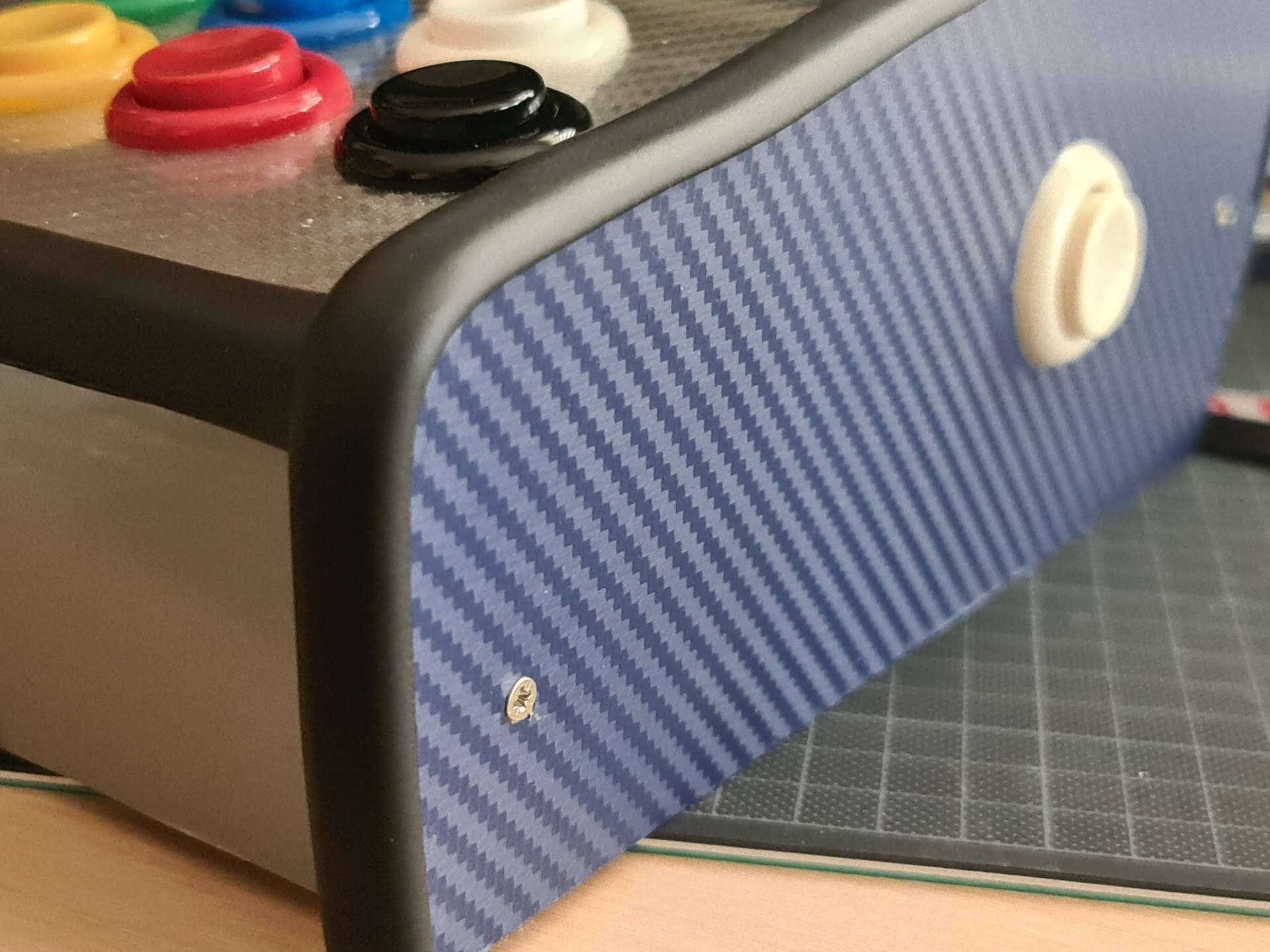
One big problem was I had no T-molds for the edges of the cabinet. You can see the MDF section on the both sides that you can see the wood/MDF texture through it. I solved that problem by discovering a nice material with a pure luck. We got a 1.5 year old baby and I ordered some rubber corner protection attachments for the furnitures in 1-2 areas in the house. 

The corner rubber parts are arrived, we used on some furniture corners but they put some strip rubber as well. Which was useless for our baby's safety with the furniture, but that stripes were great and useful for the cabinet I'm making.

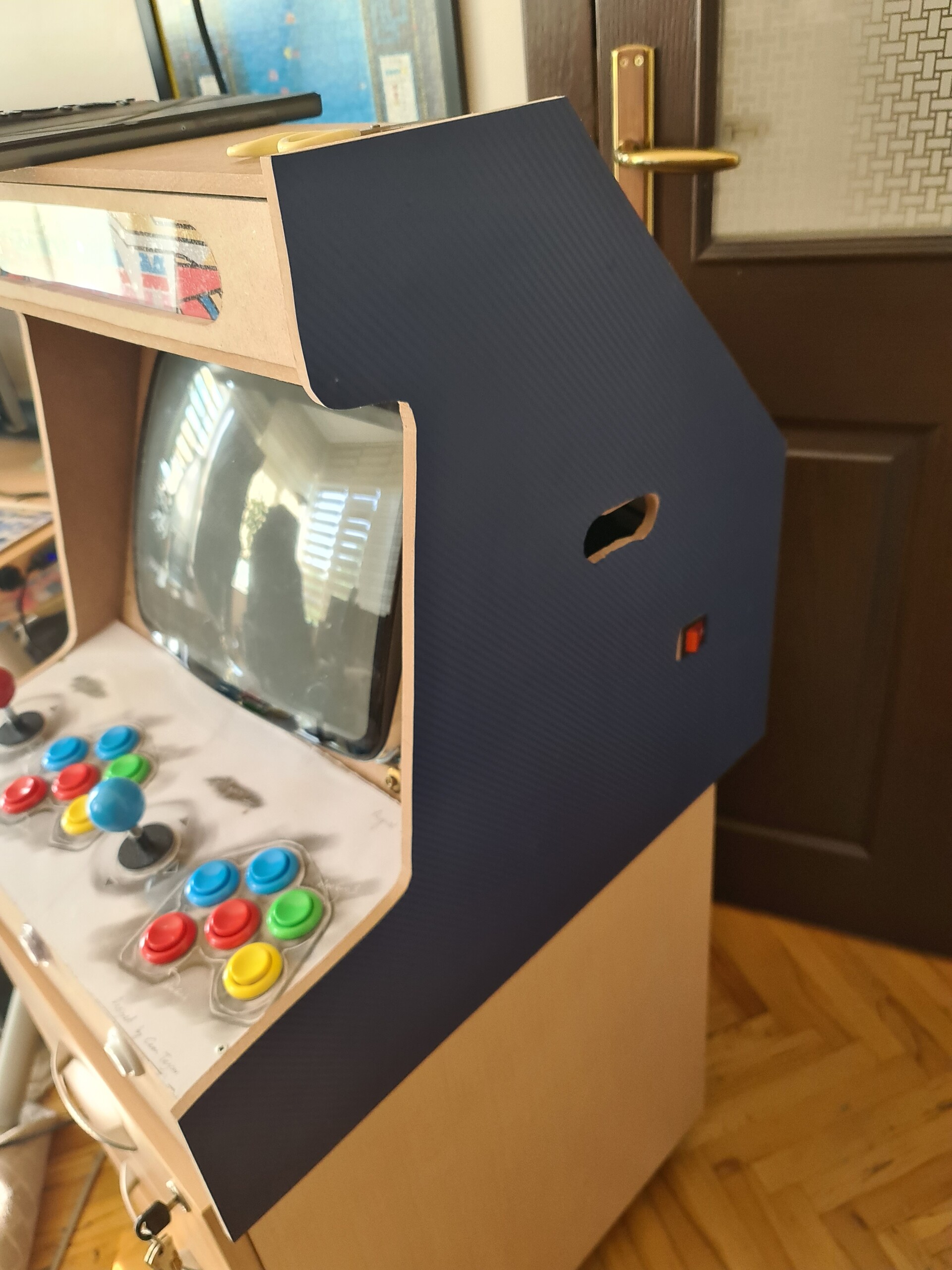
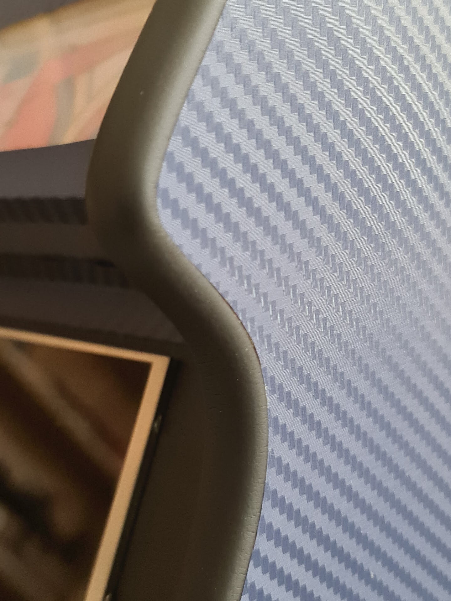
It looks flexible and durable. So I used it on all the edges through the side parts as well.

It looks great but it needed some stapling to secure the connection better. Because I don't like it when it peeled of at the corner bends. I know it doesn't look good but until I find a better glue solution, it's better to keep it that way.

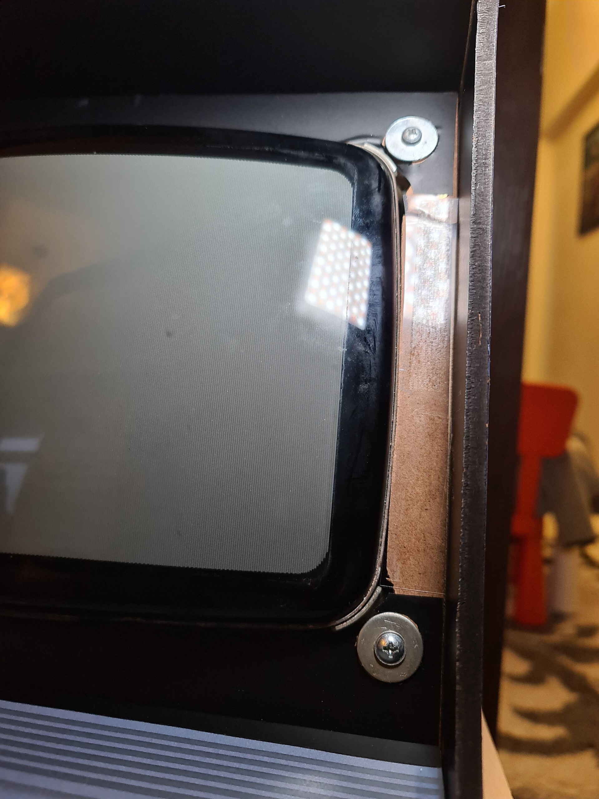
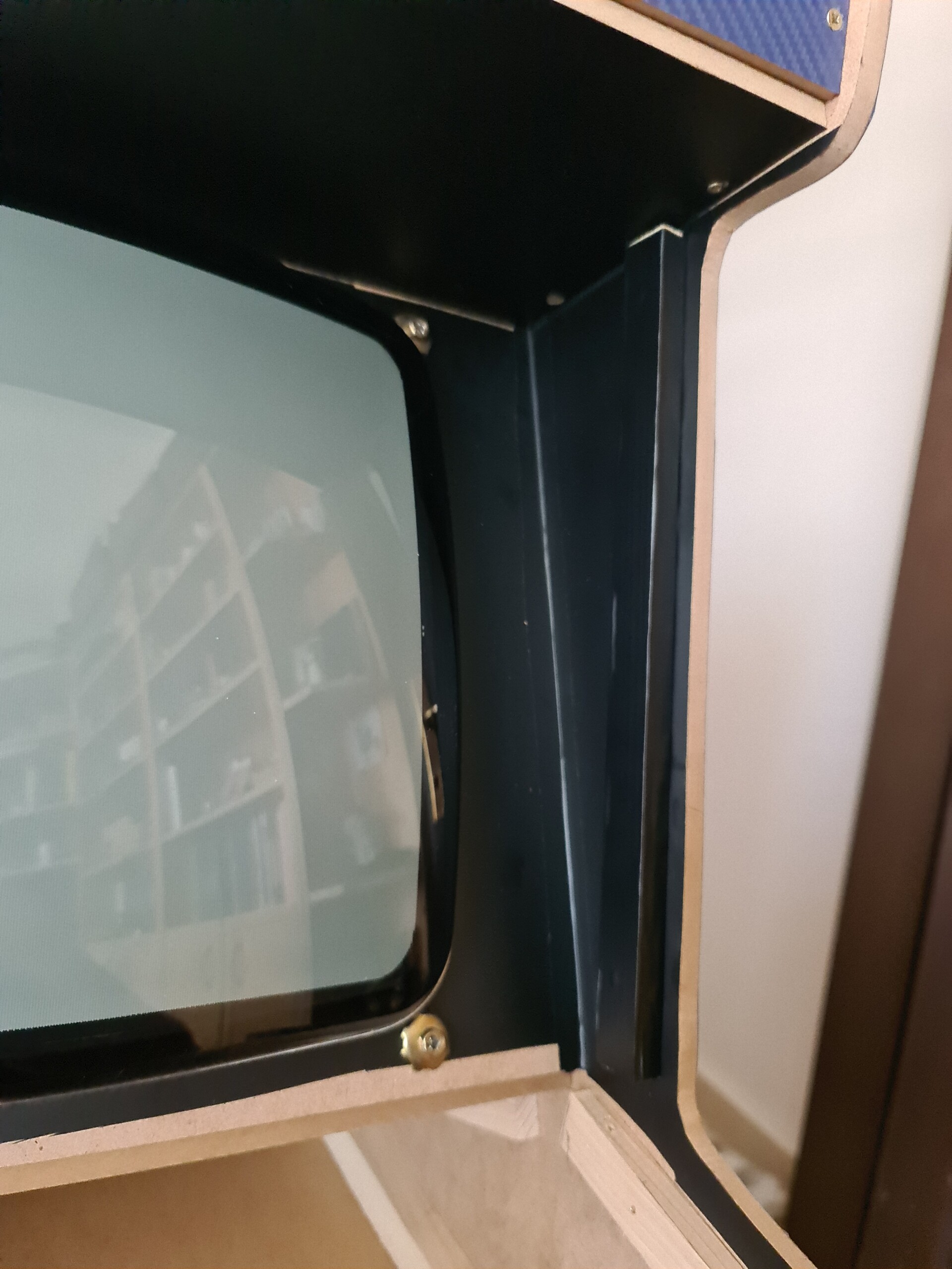
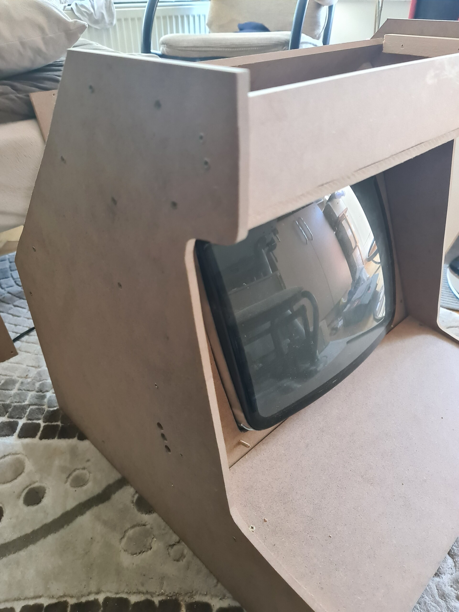
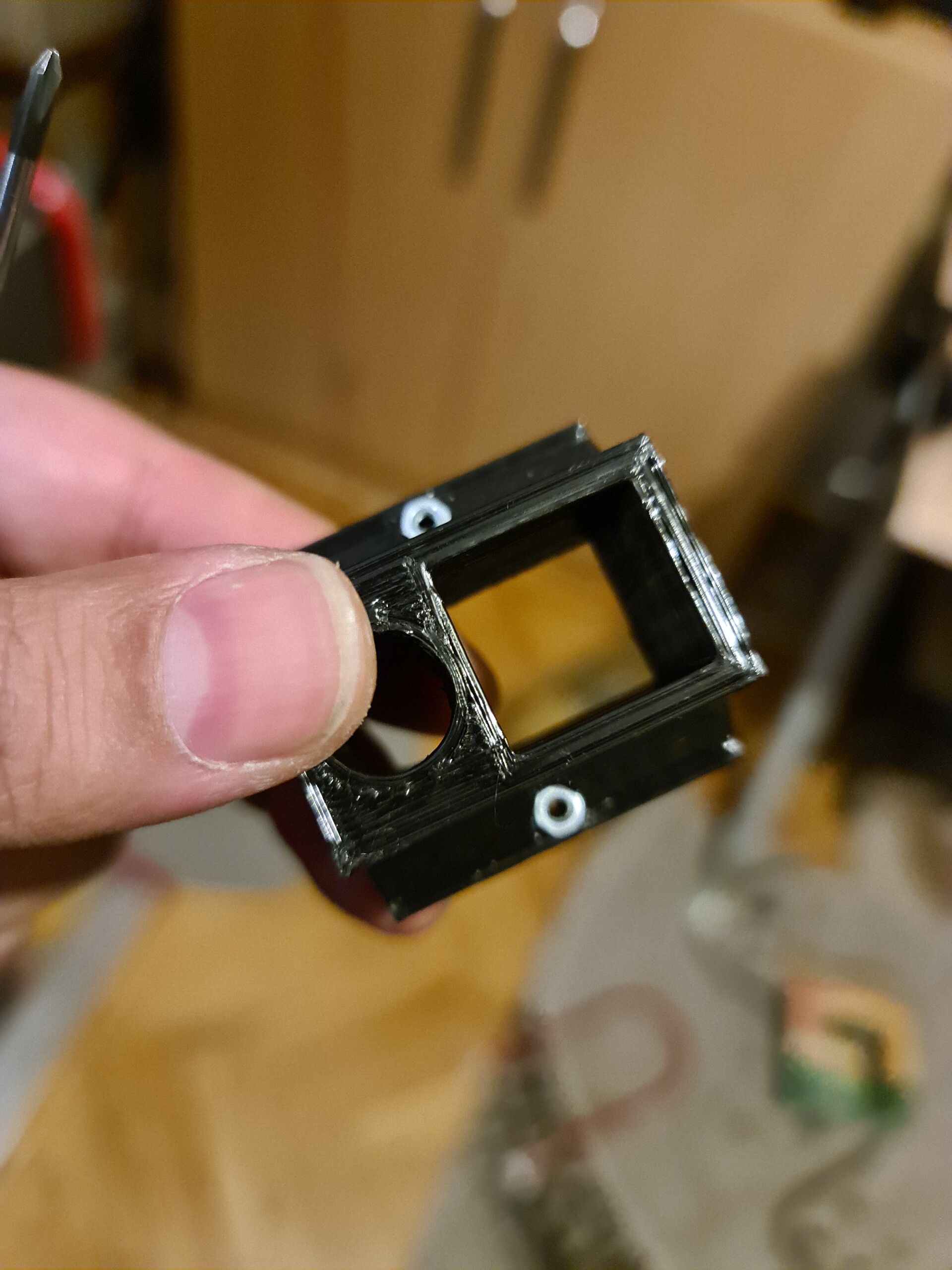
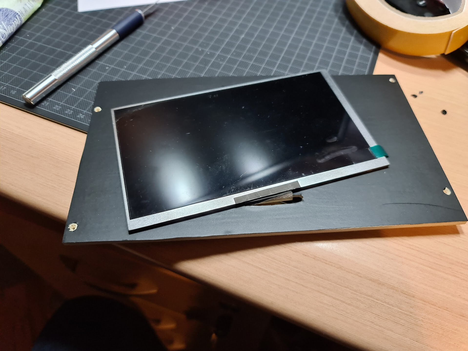
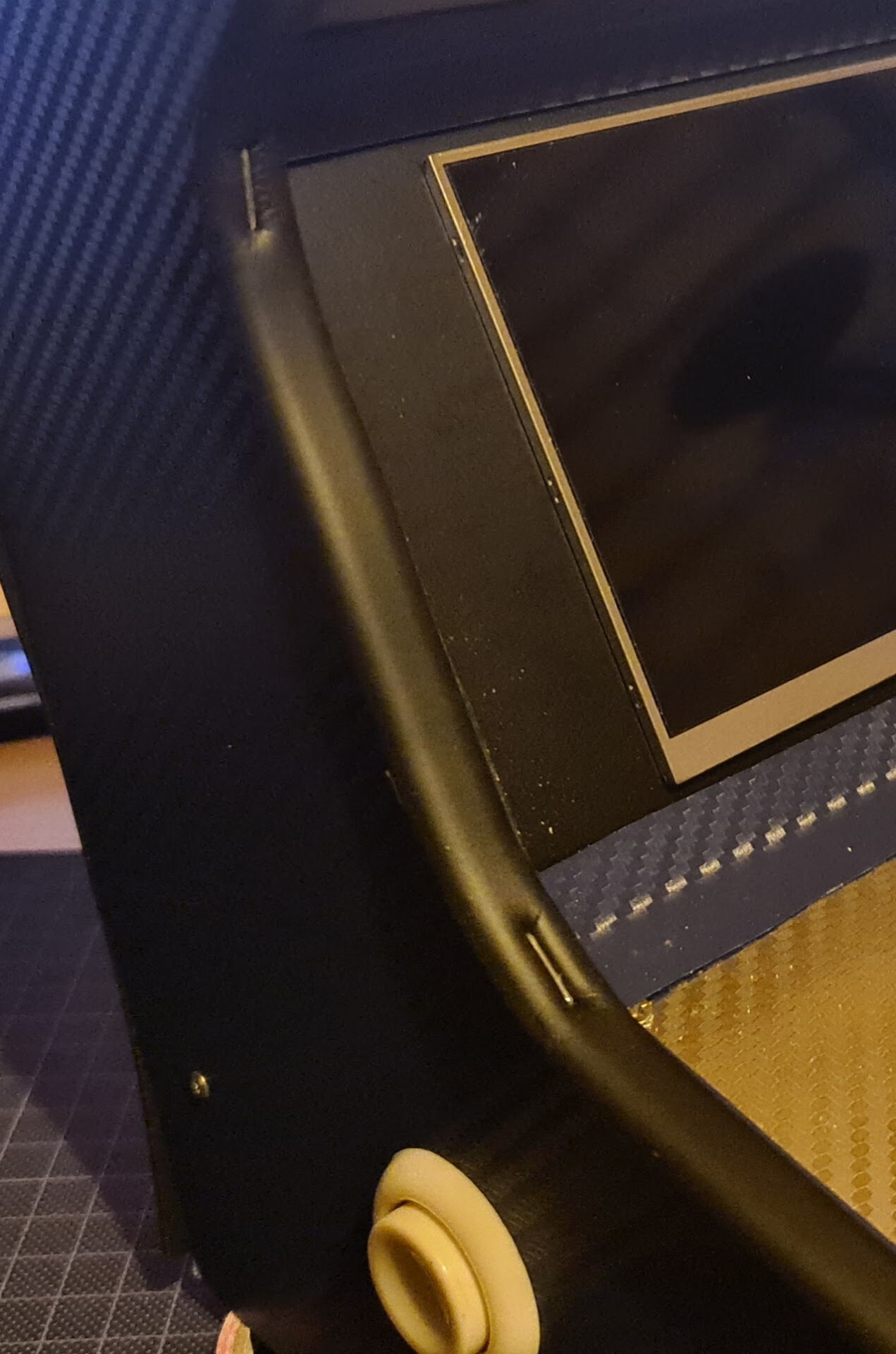
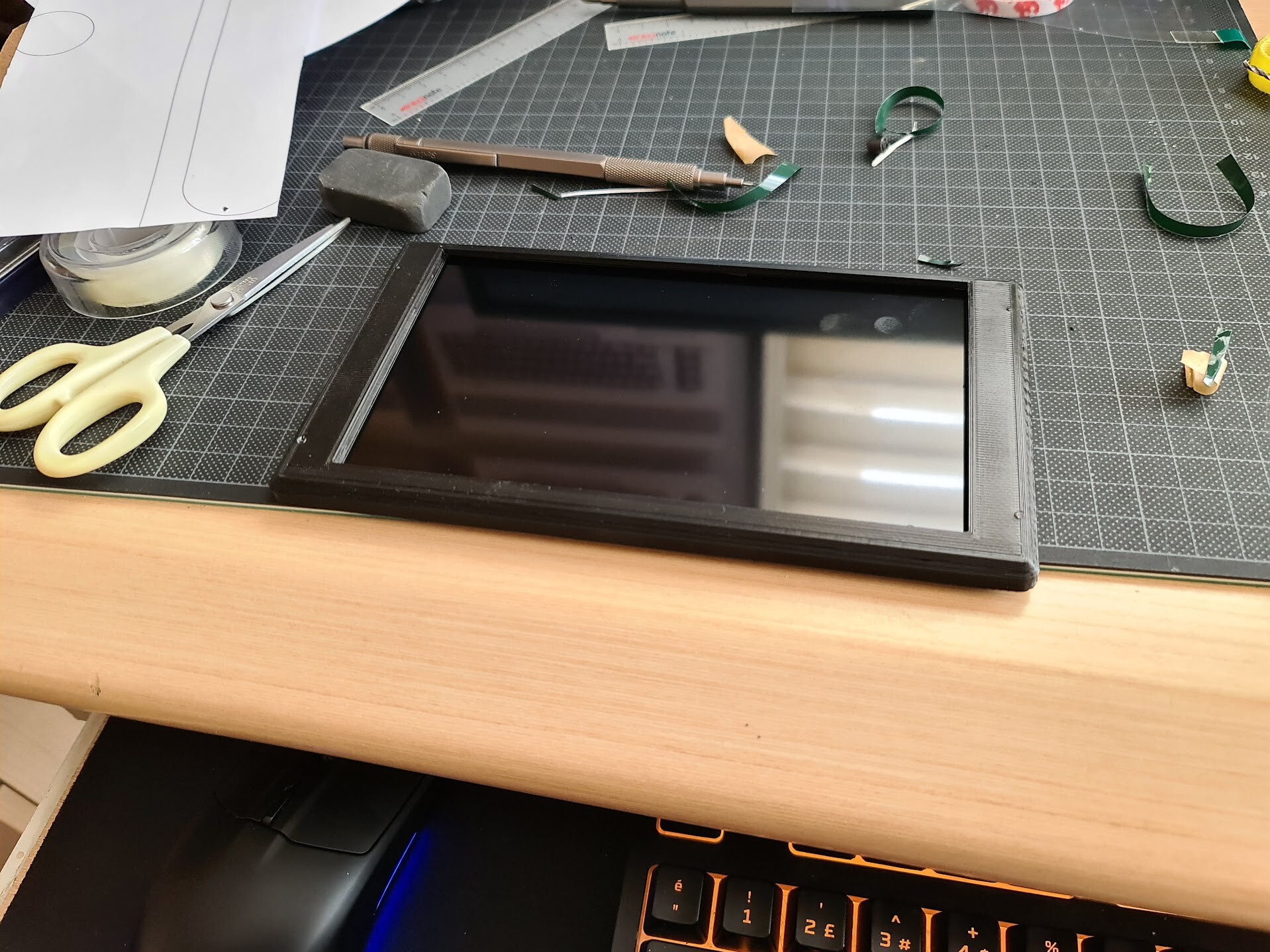
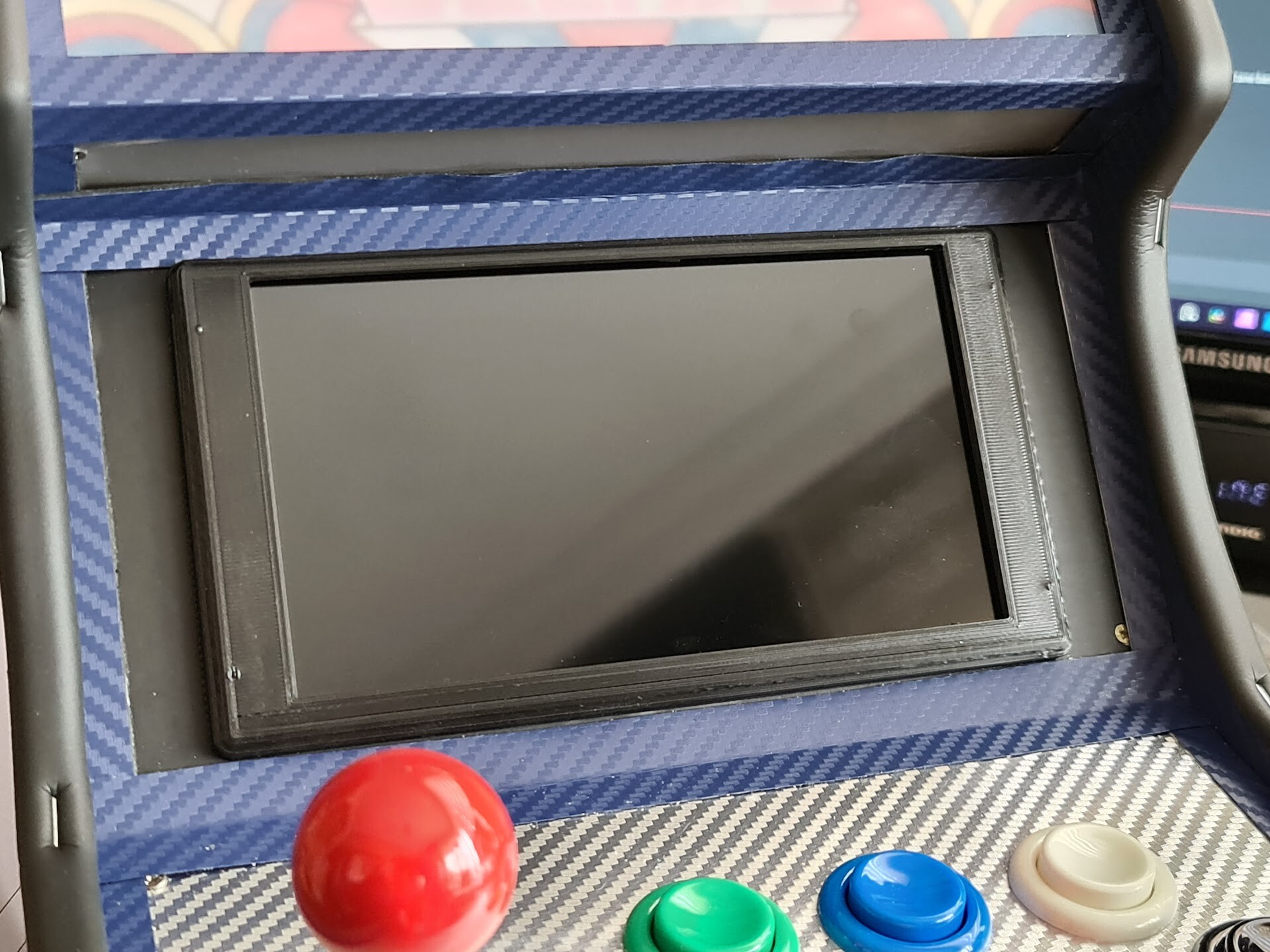
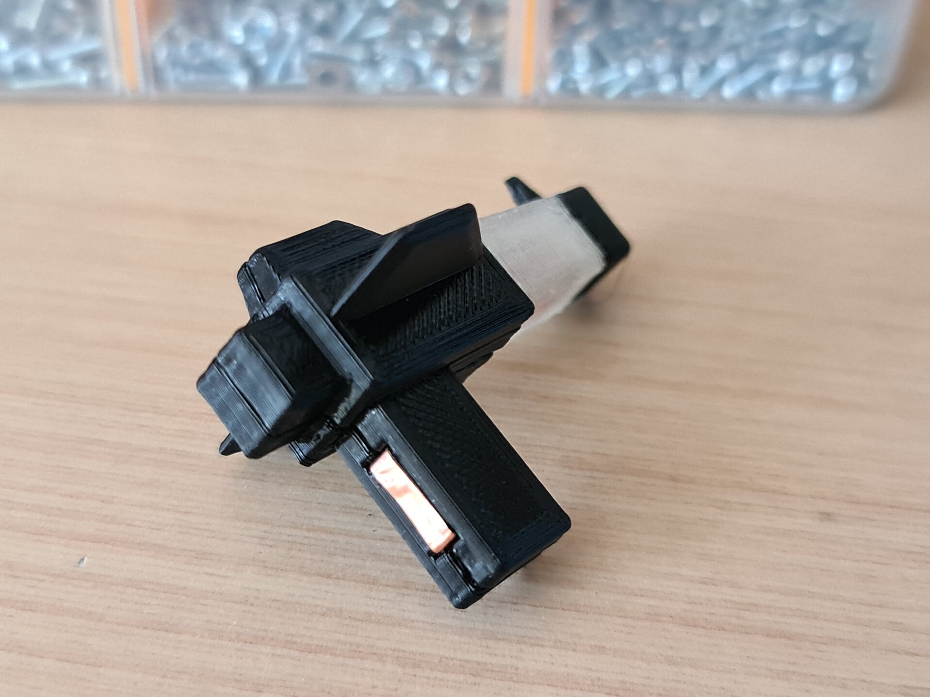
I designed and 3d printed a screen frame.

Screen I'm using is a waveshare 7" DPI screen which I was holding for a long time for a project. finally got it used on. I 3d printed it in a beautiful evening when we got a lovely snowing in Ankara.

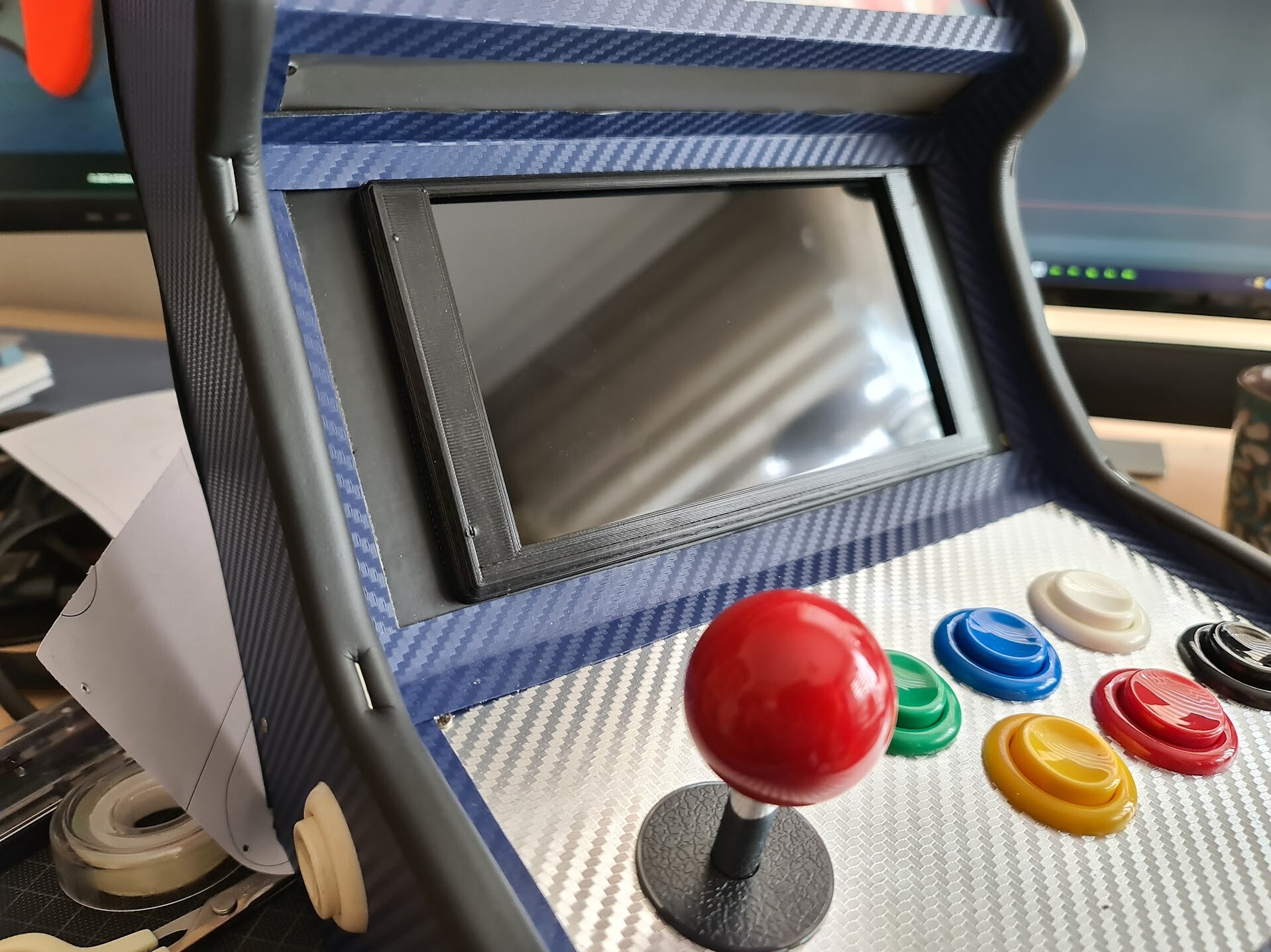
I applied the printed frame and it looks great.

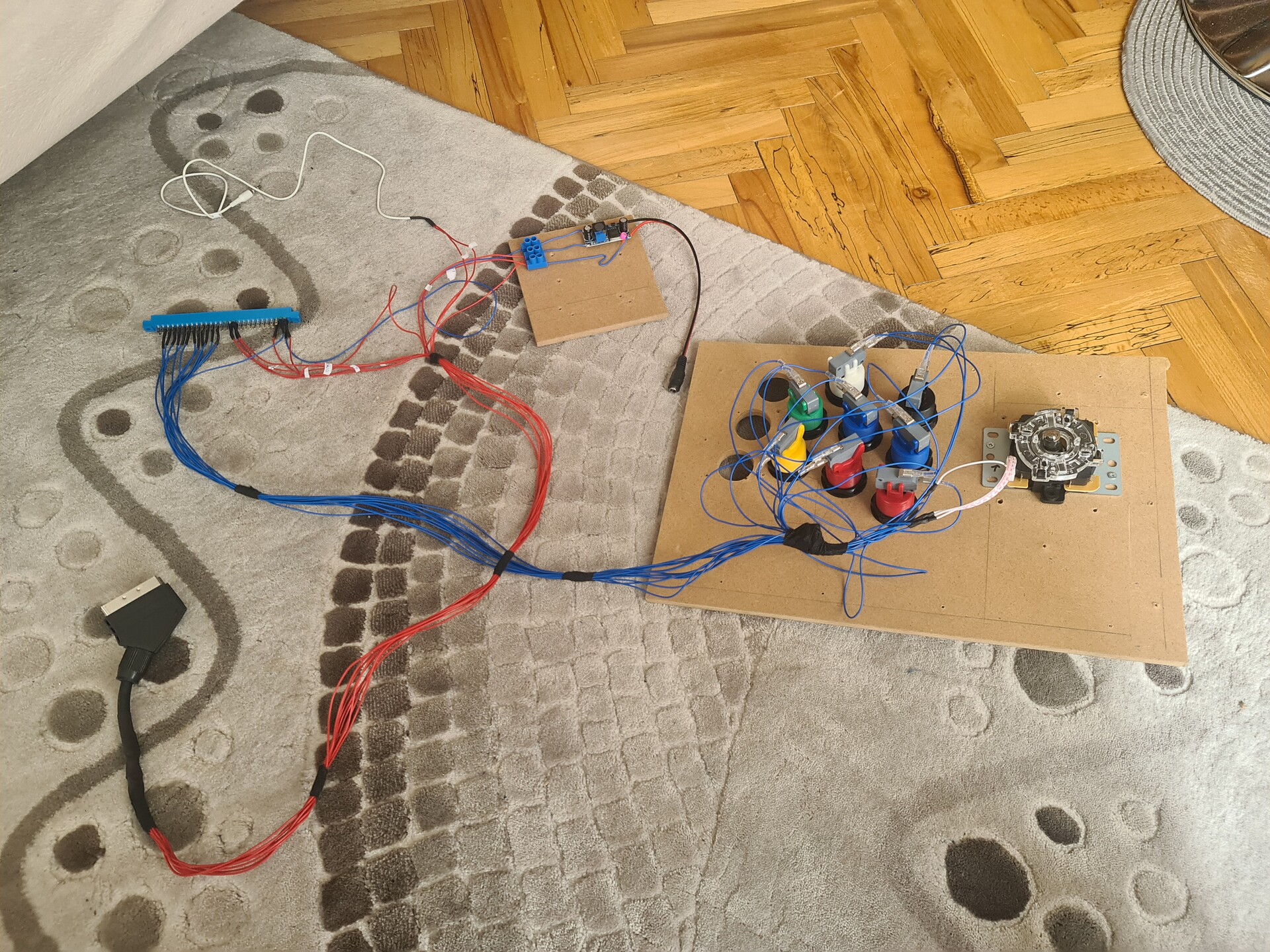
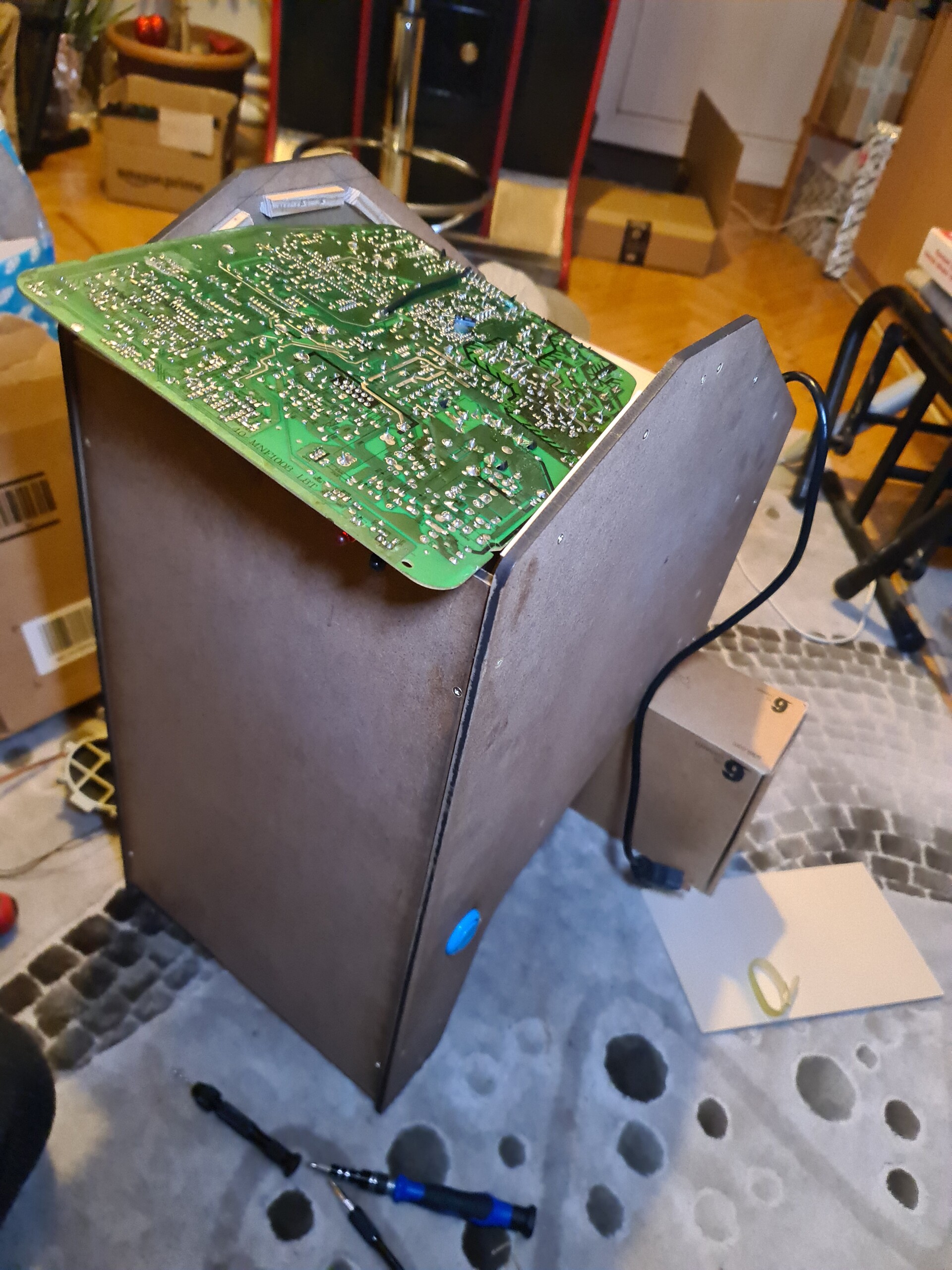
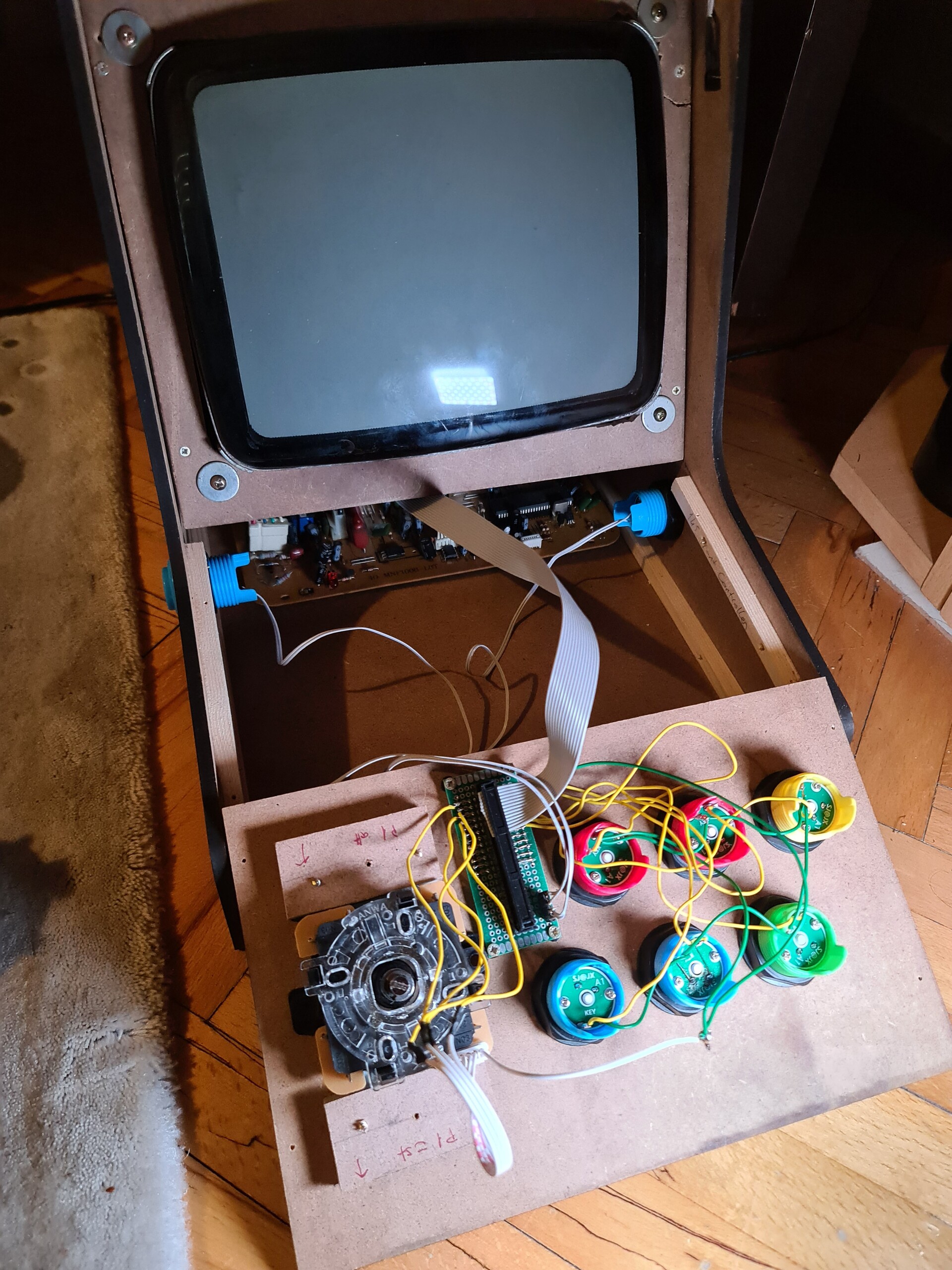
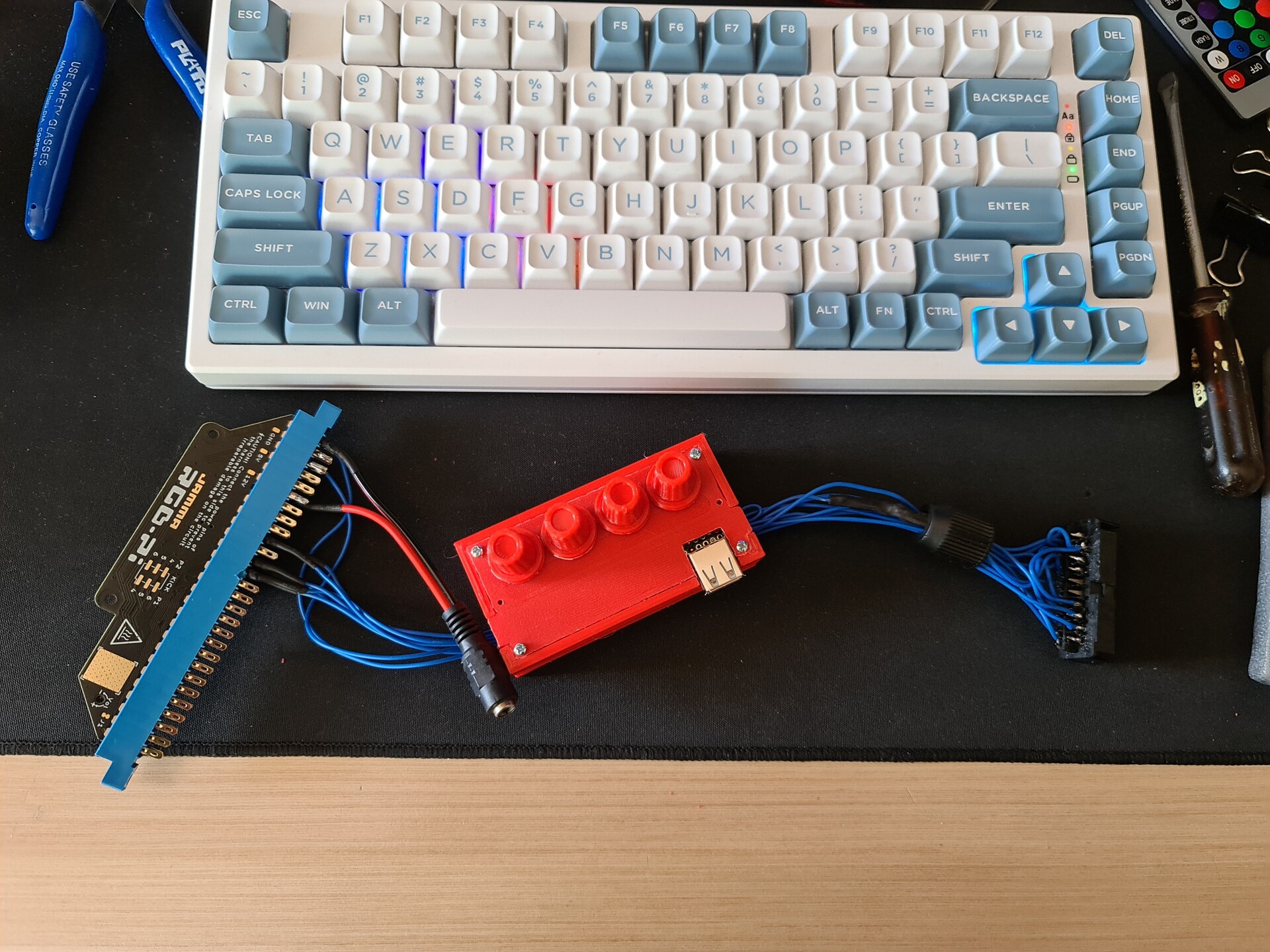
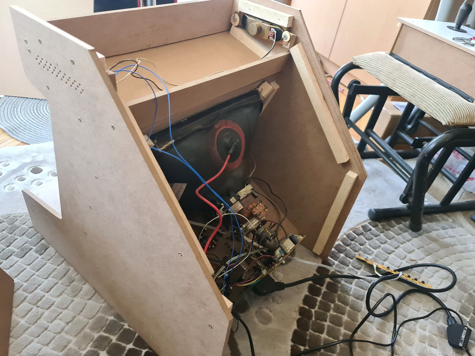
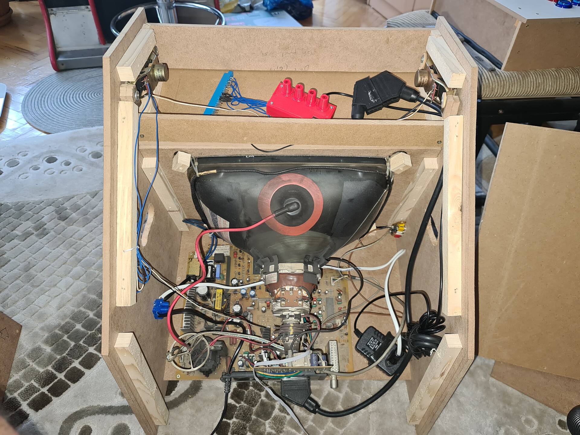
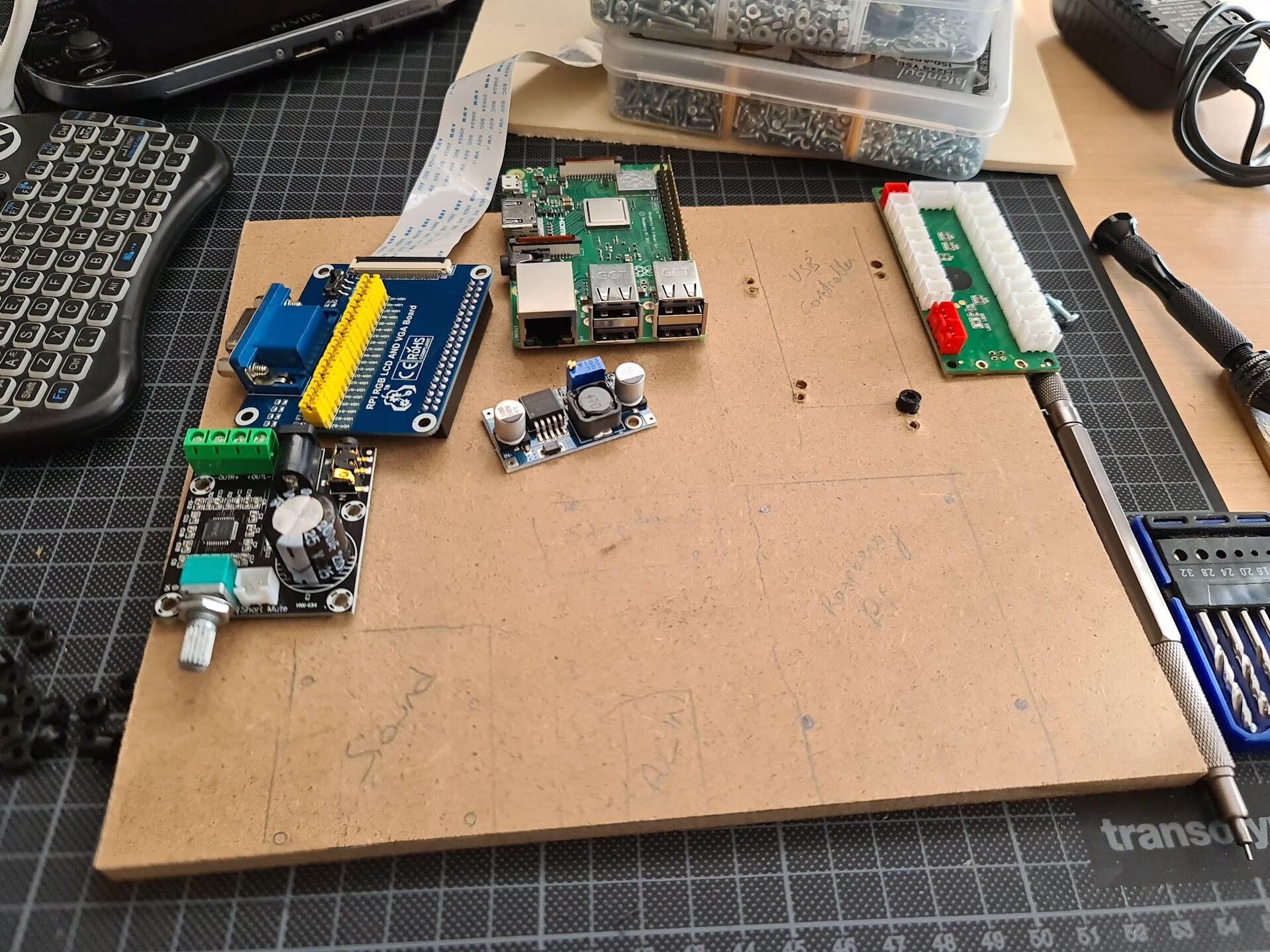
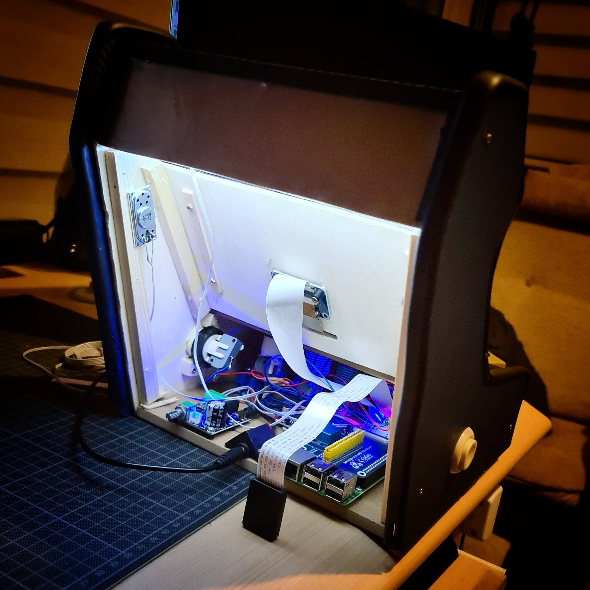
Now it's time for the electronic assembly!

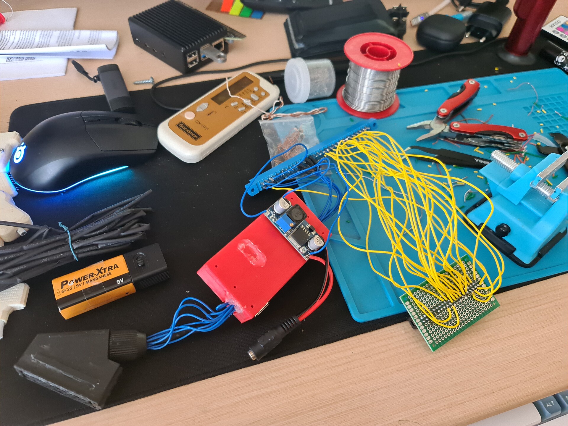
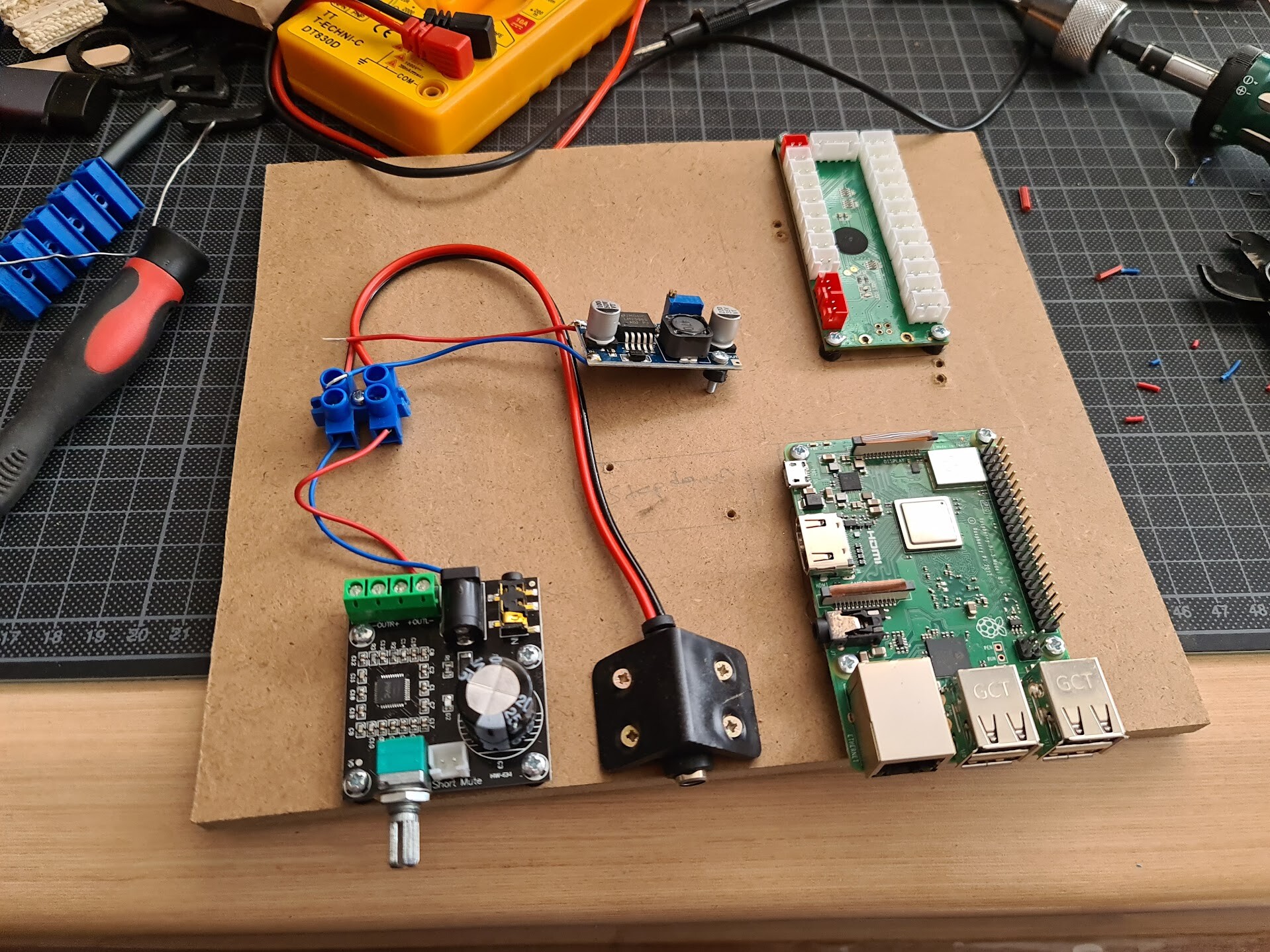
The electronic components I used on this projects are:

  • Raspberry Pi 3B+
  • DPI screen hat for raspberry pi
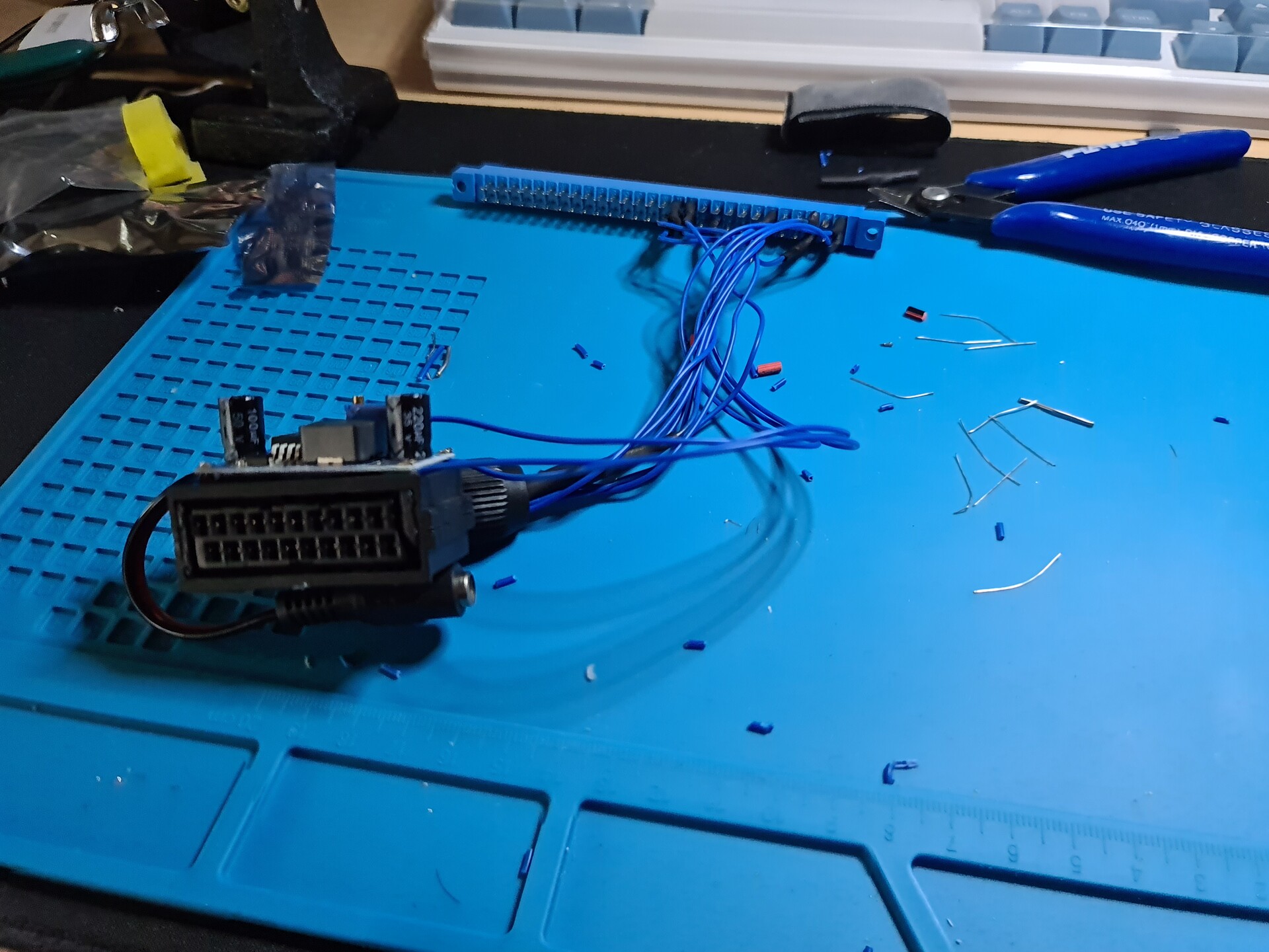
  • DC-DC Step-down voltage circuit
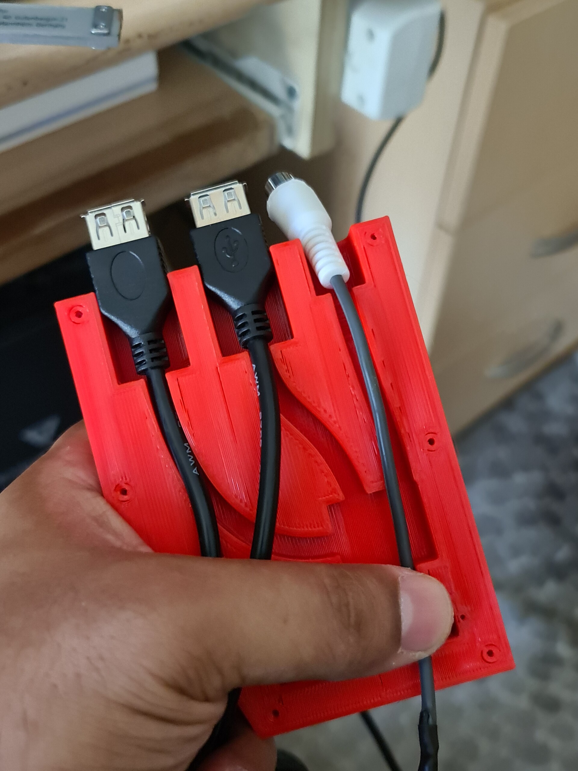
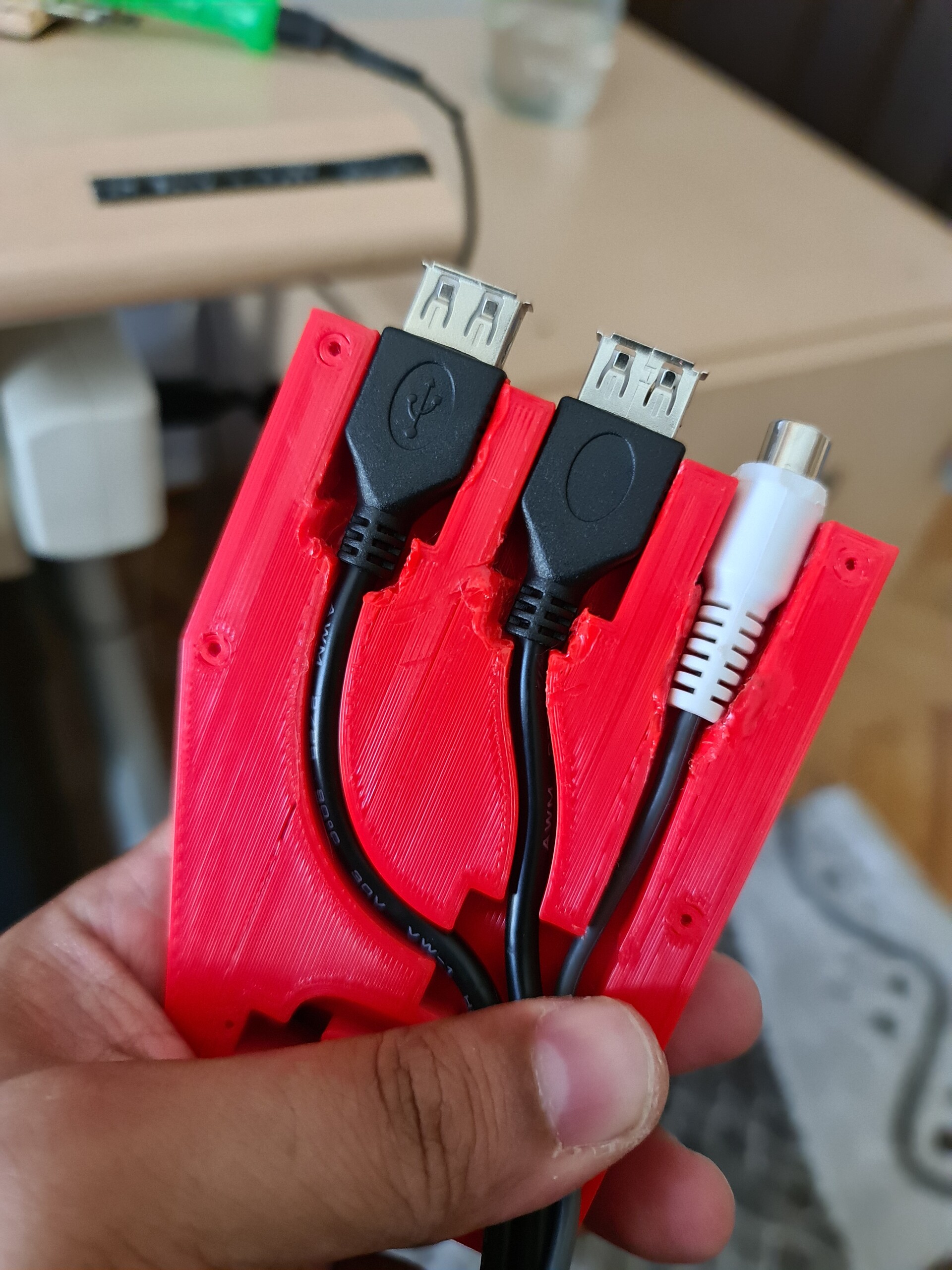
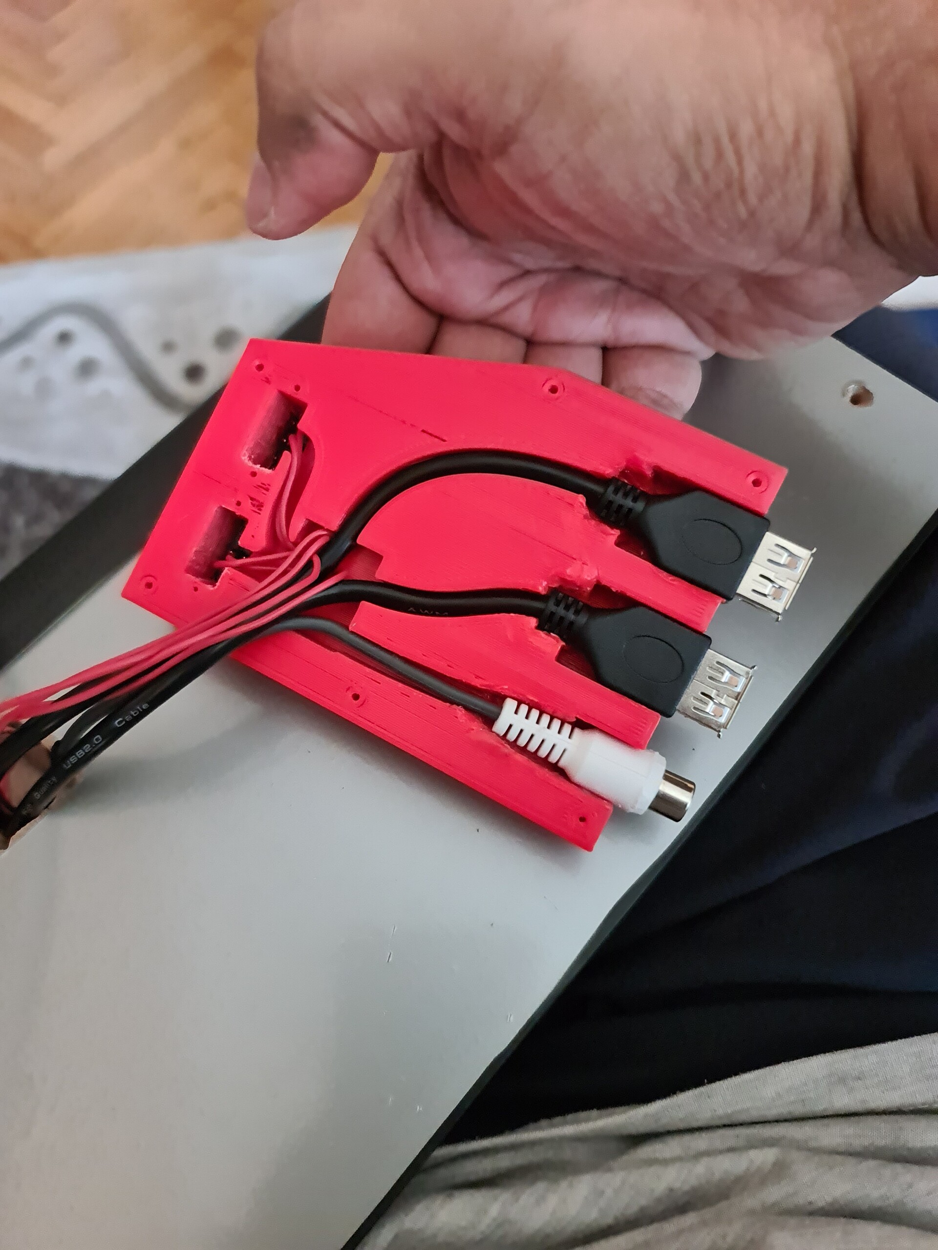
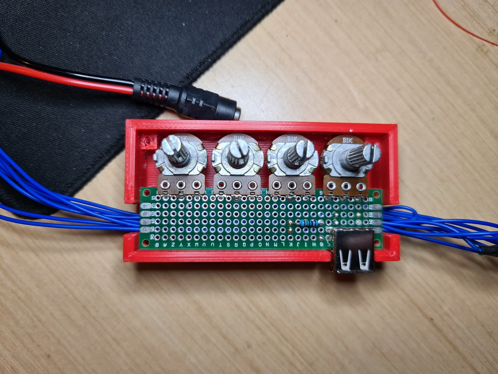
  • USB game controller circuit
  • Audio amphilicator circuit
  • DC jack connector
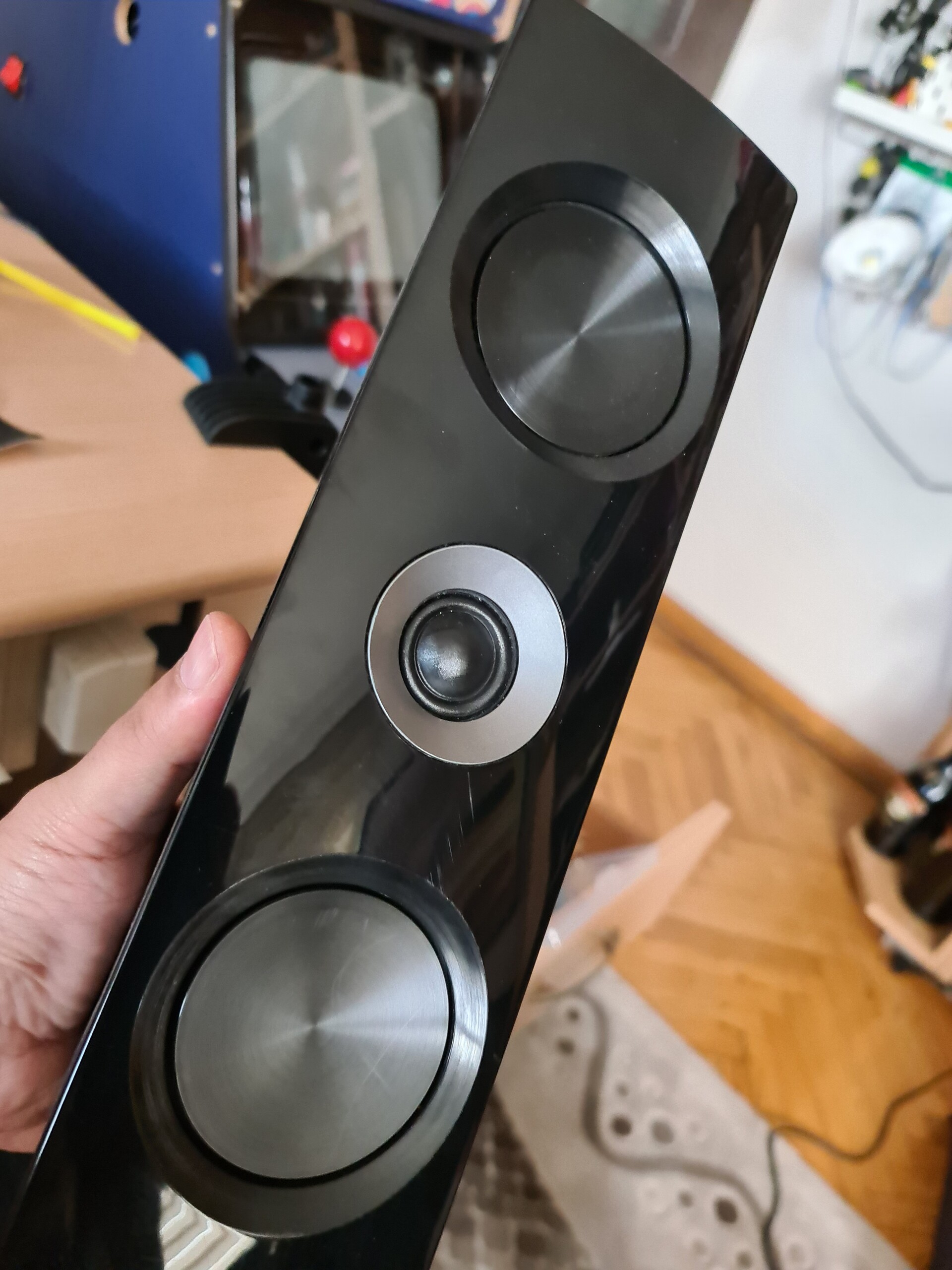
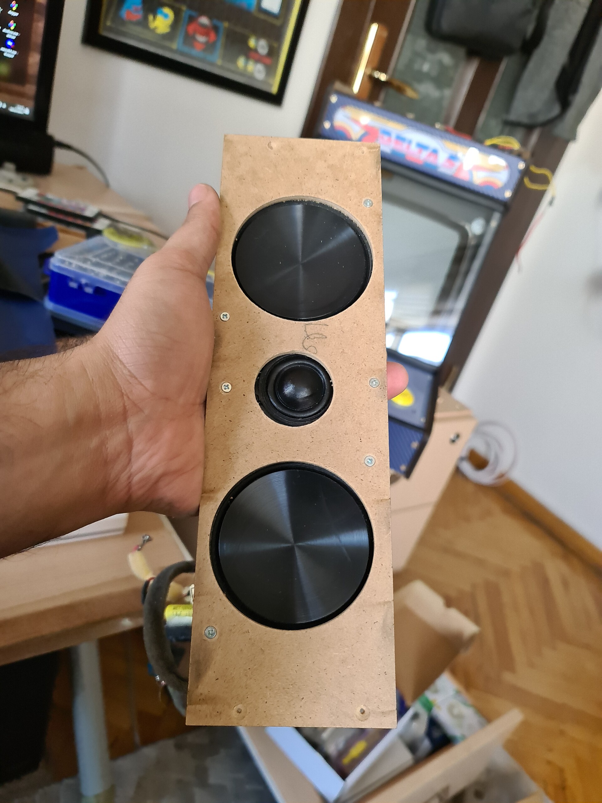
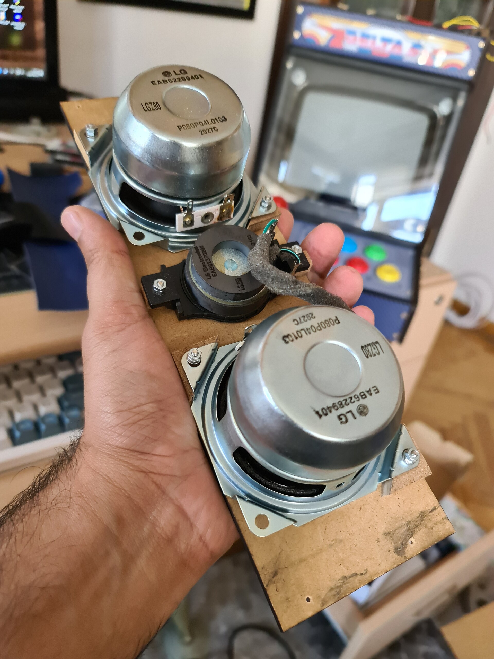
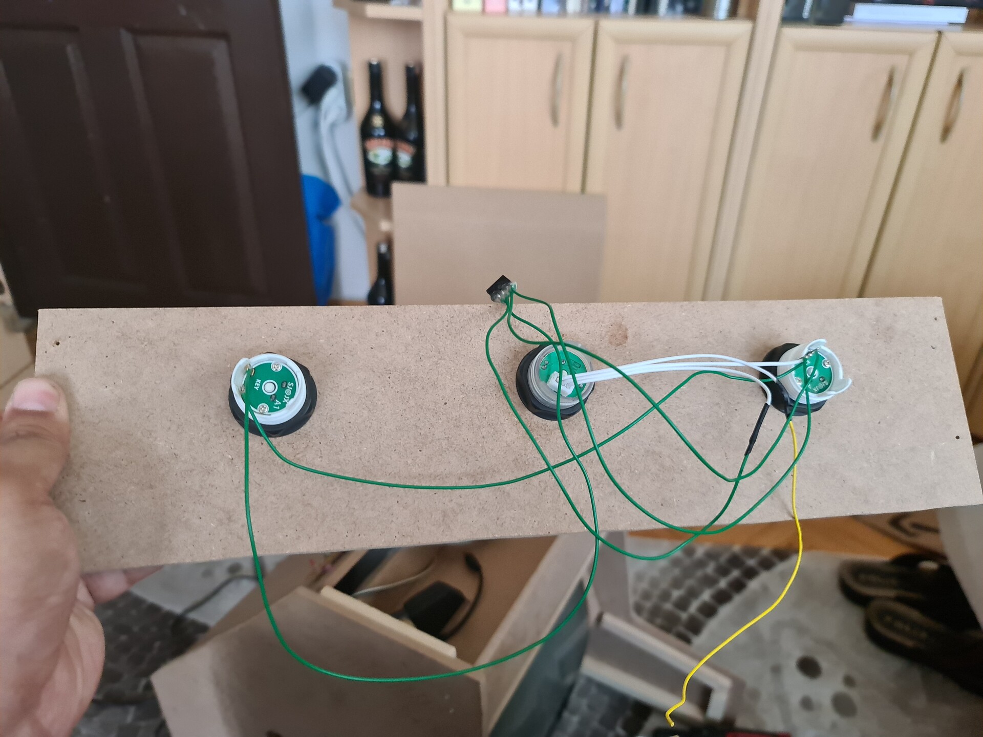
  • 2 pcs 8 ohm speakers

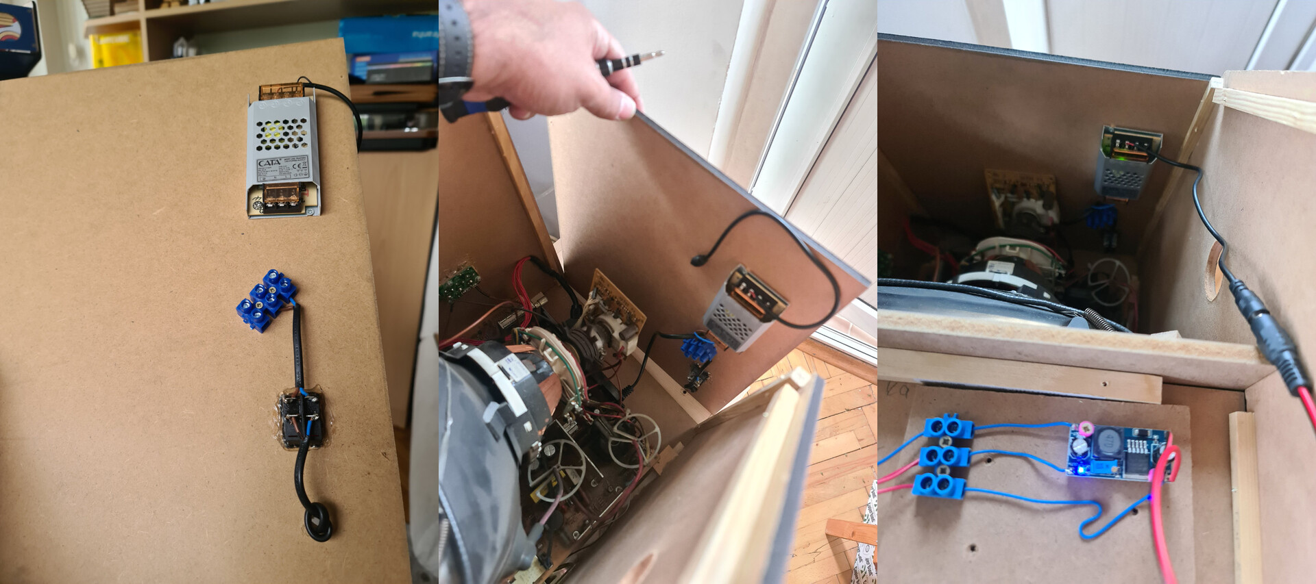
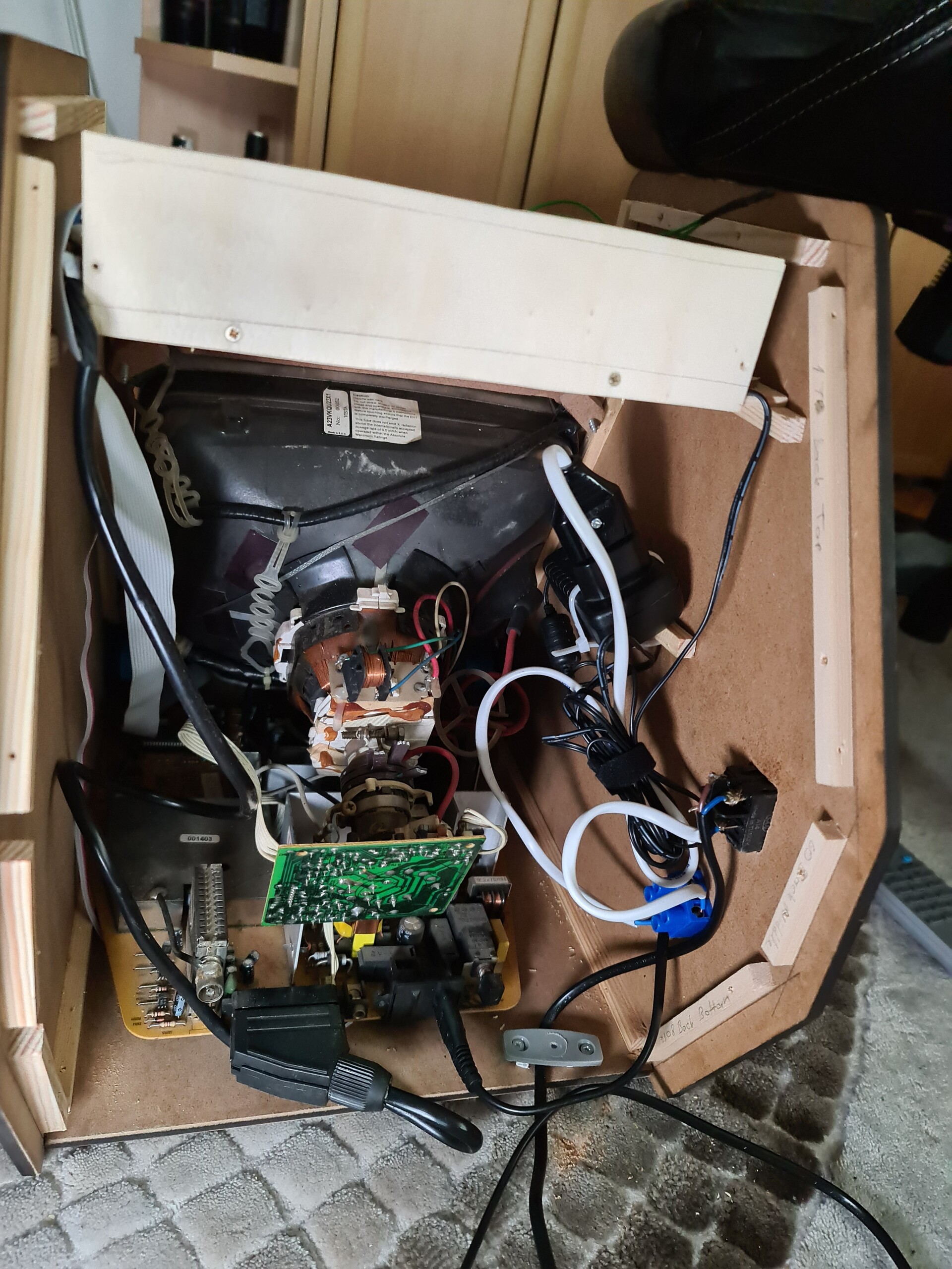
I decided to feed the system with 12V DC adapter since the LED stripes for the lighting works with 12V DC. But since the rest of the components works with 5V DC, I used a step down converter to set 5V output from the 12V input.

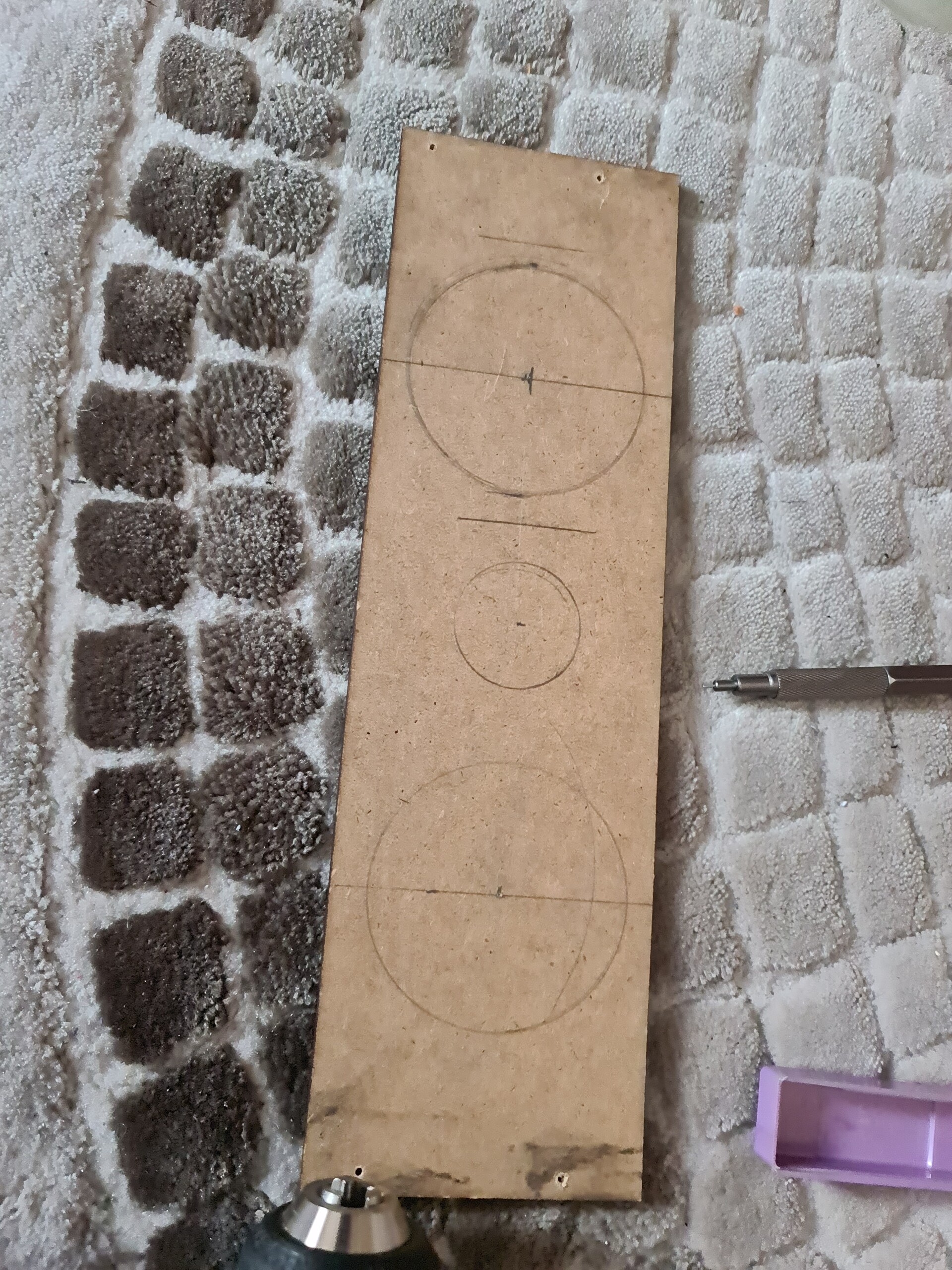
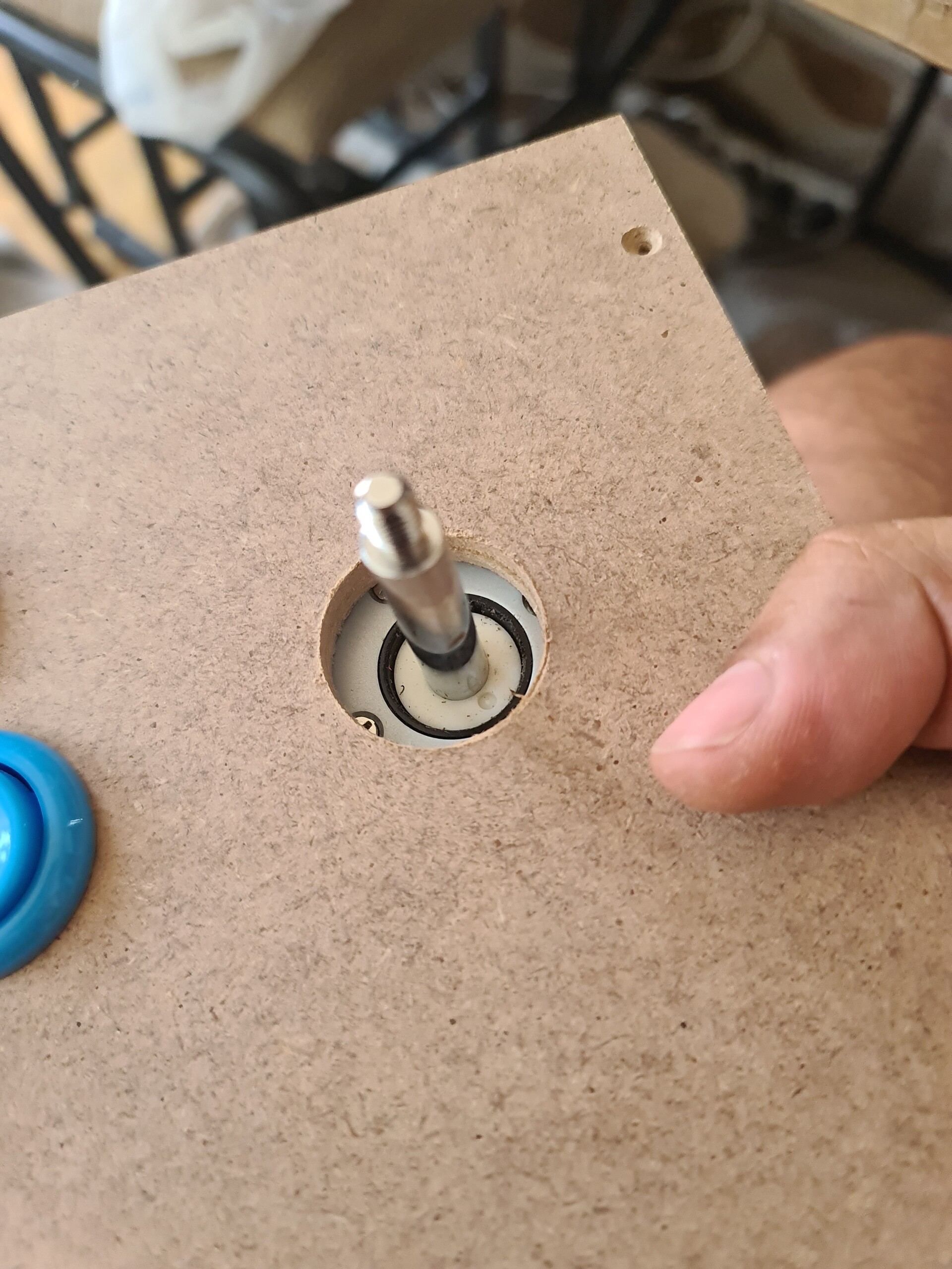
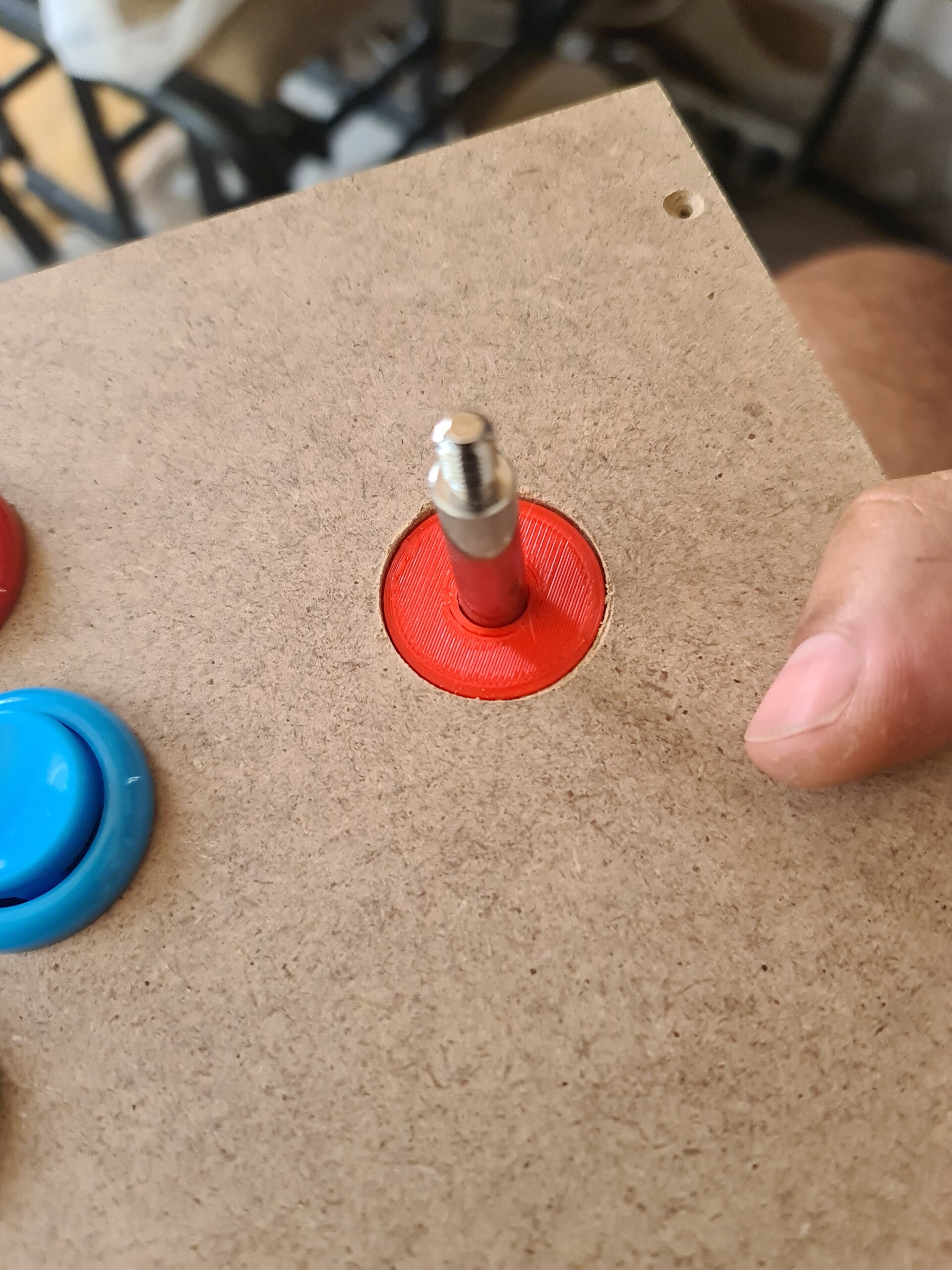
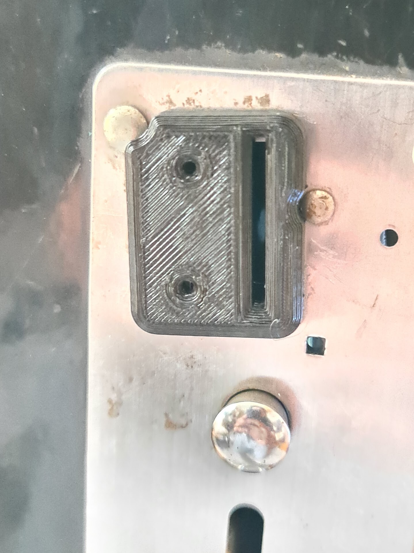
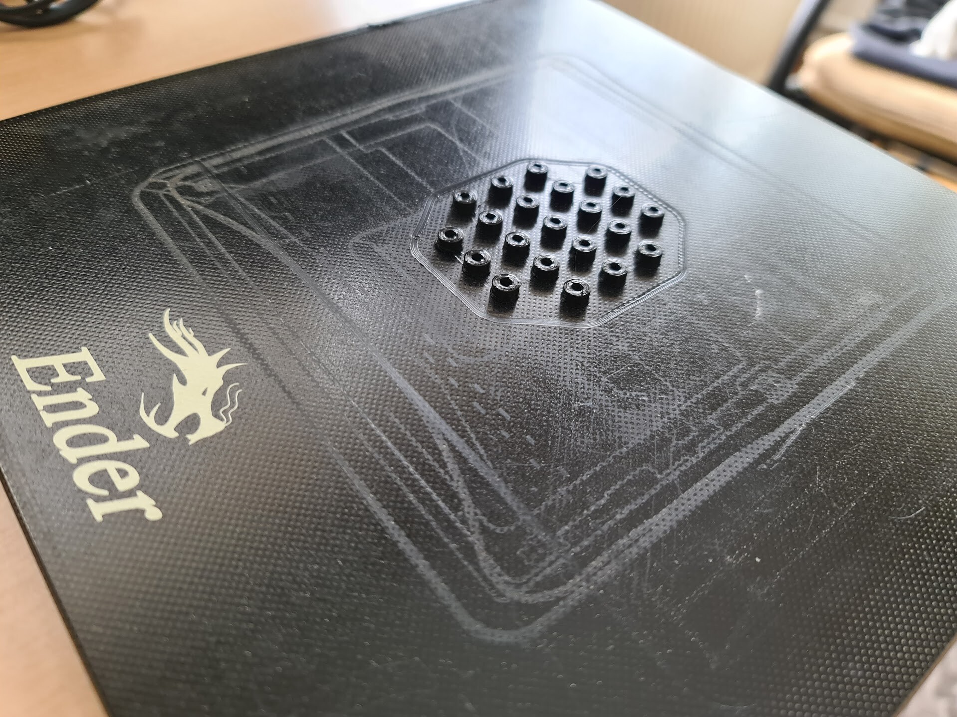
I sketched some placement over the bottom MDF board to fix the components. I also 3d printed some rings to offset the components from the surface when I screw them.

This is the placement:

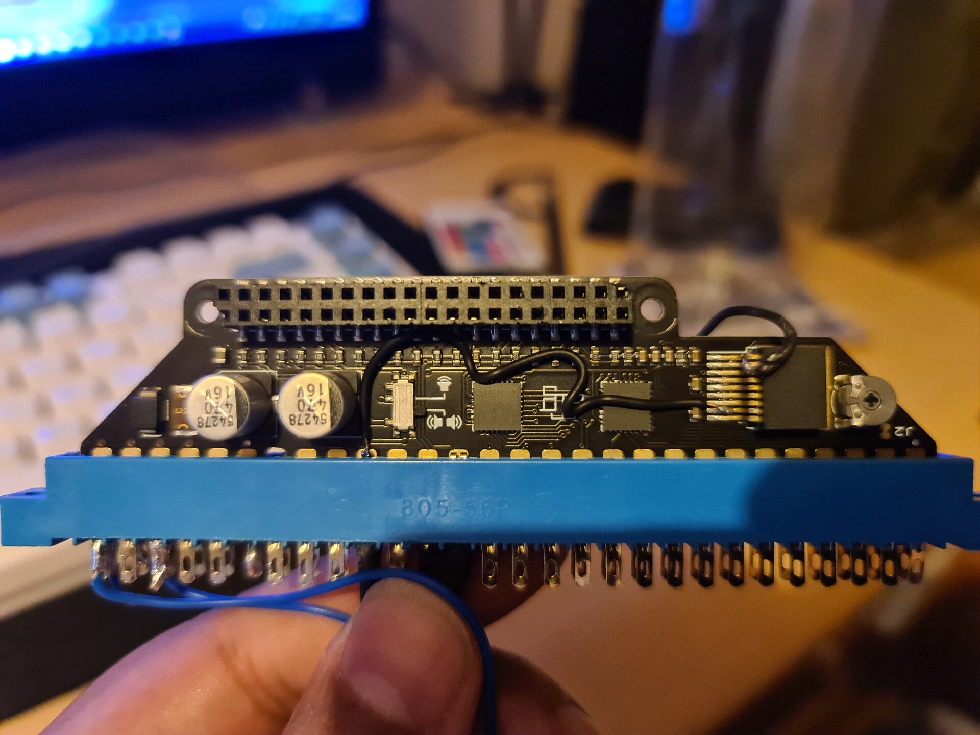
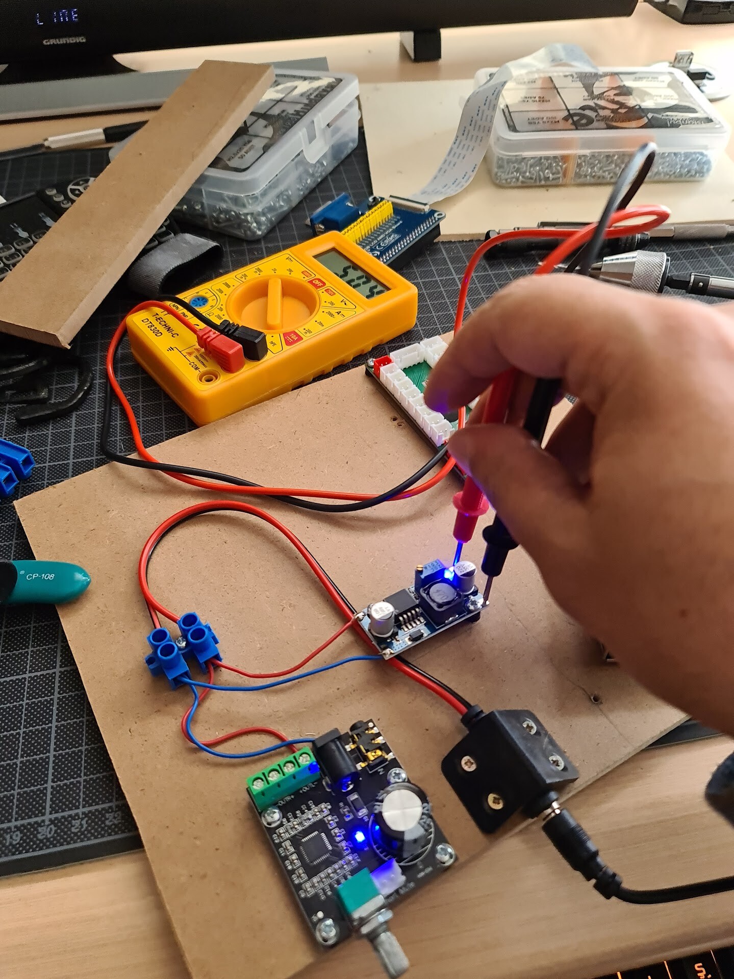
I adjusted the step-down circuit to output 5.04 volts.

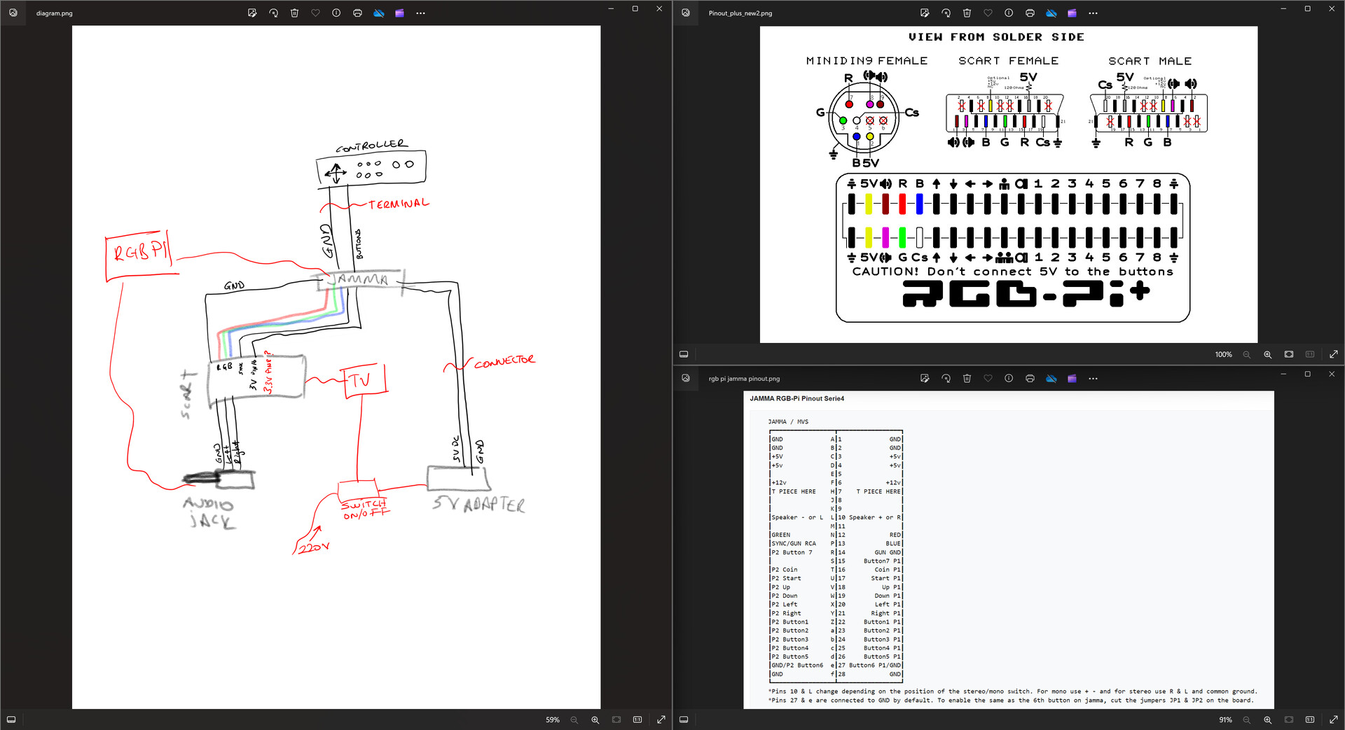
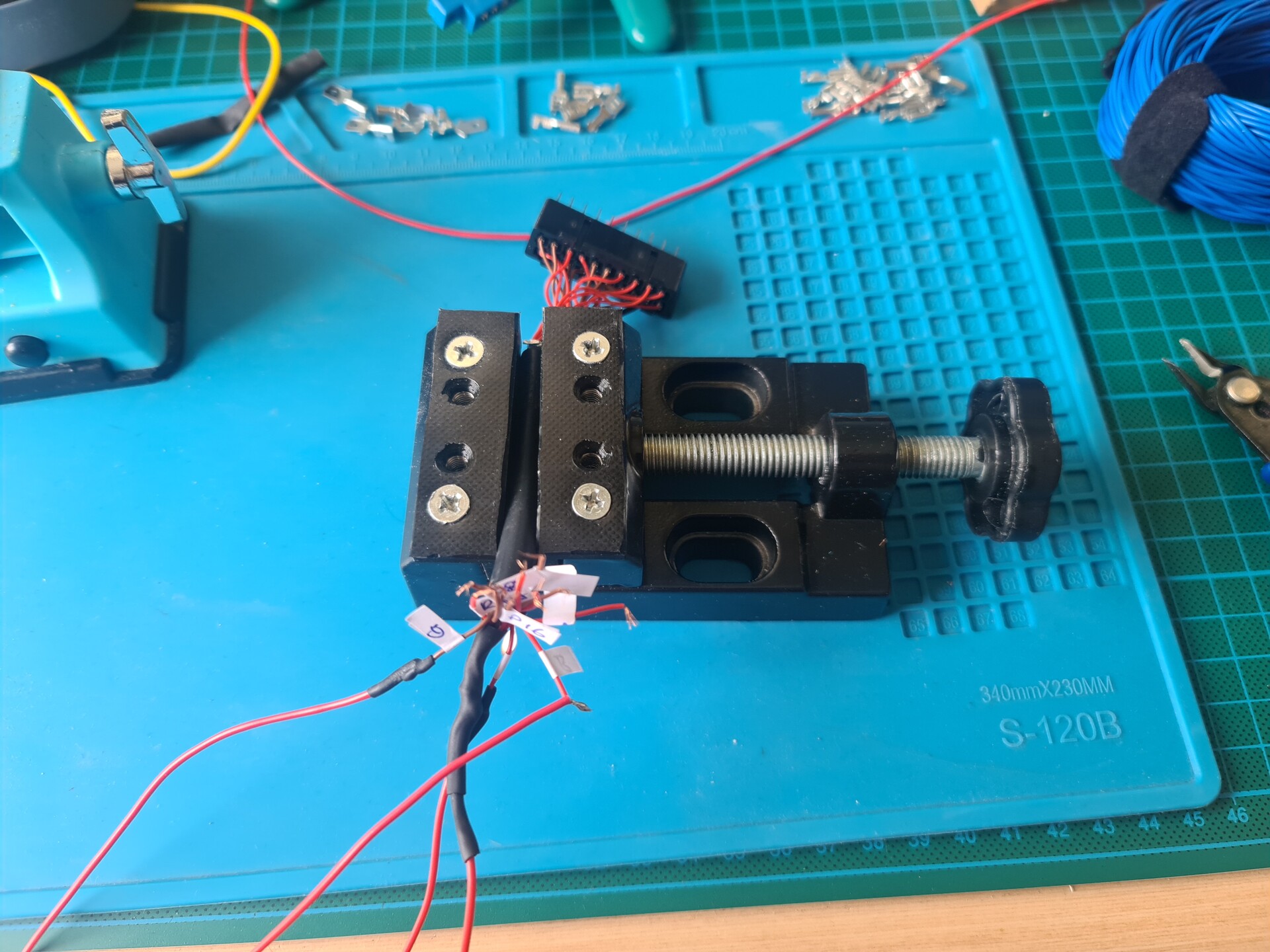
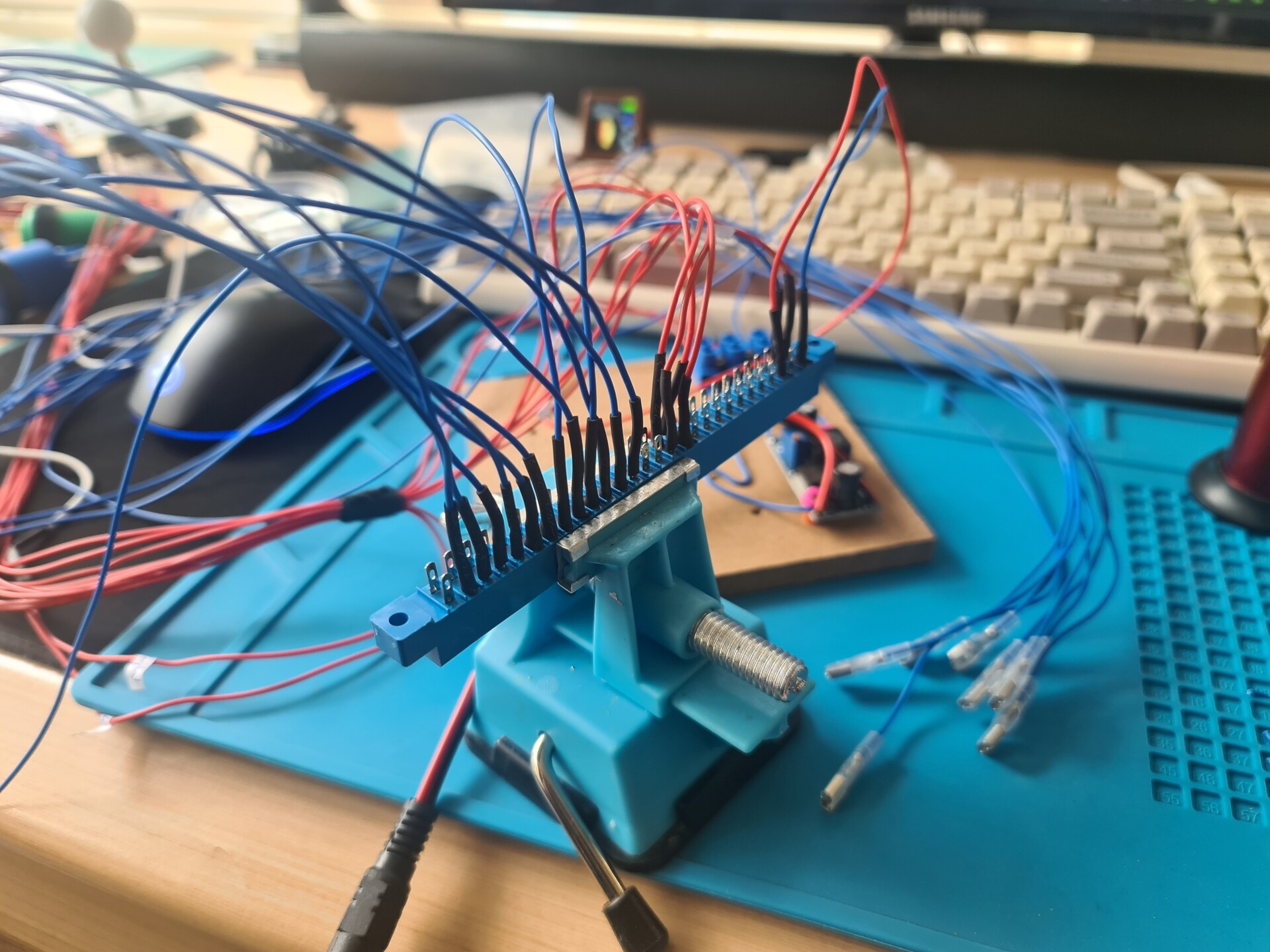
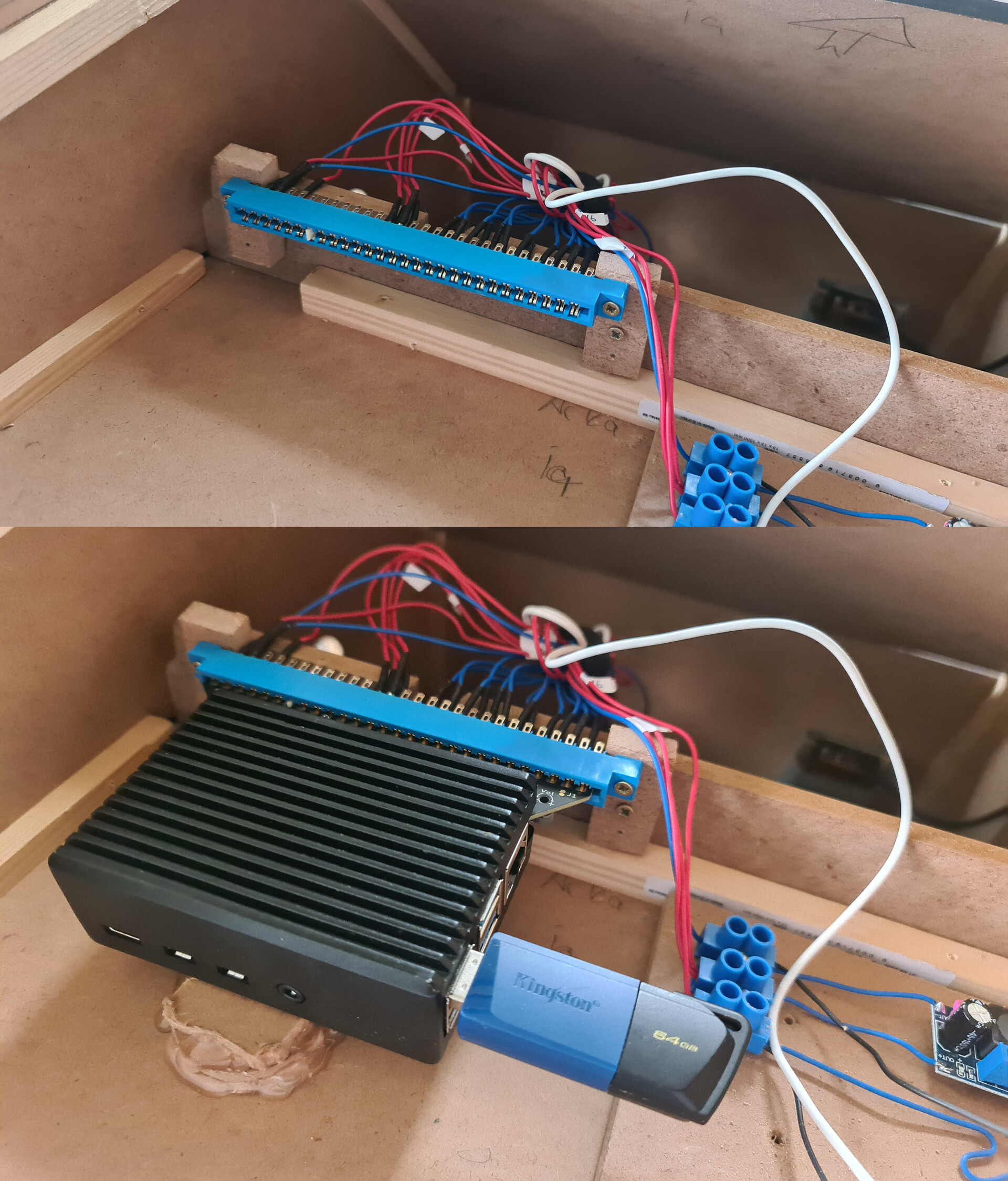
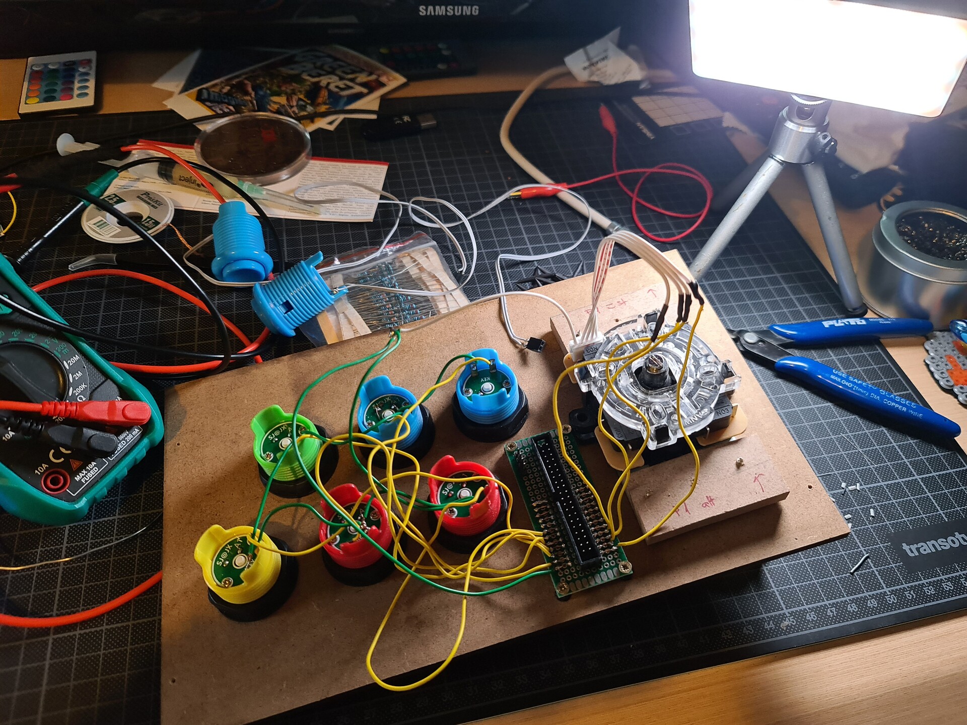
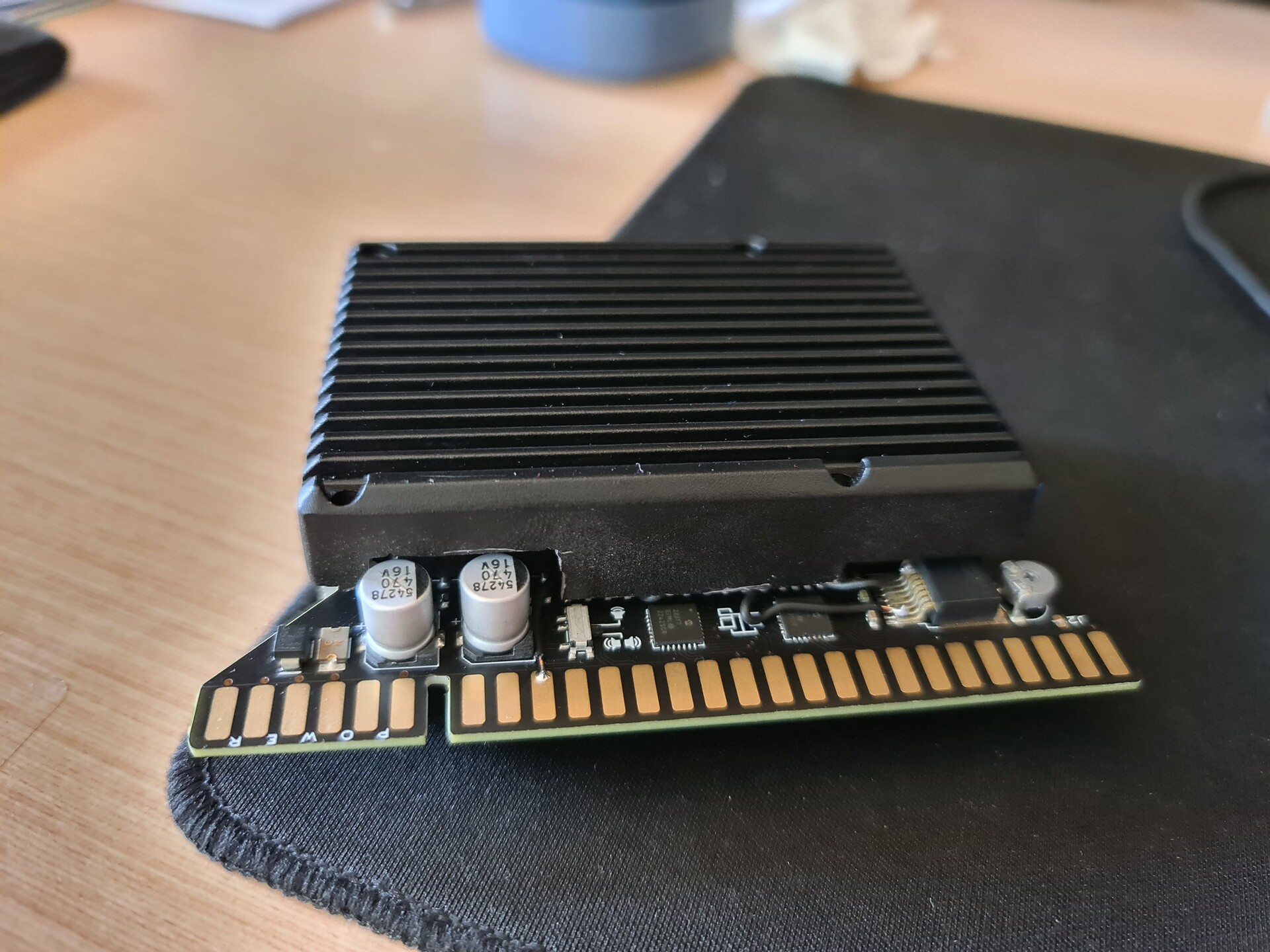
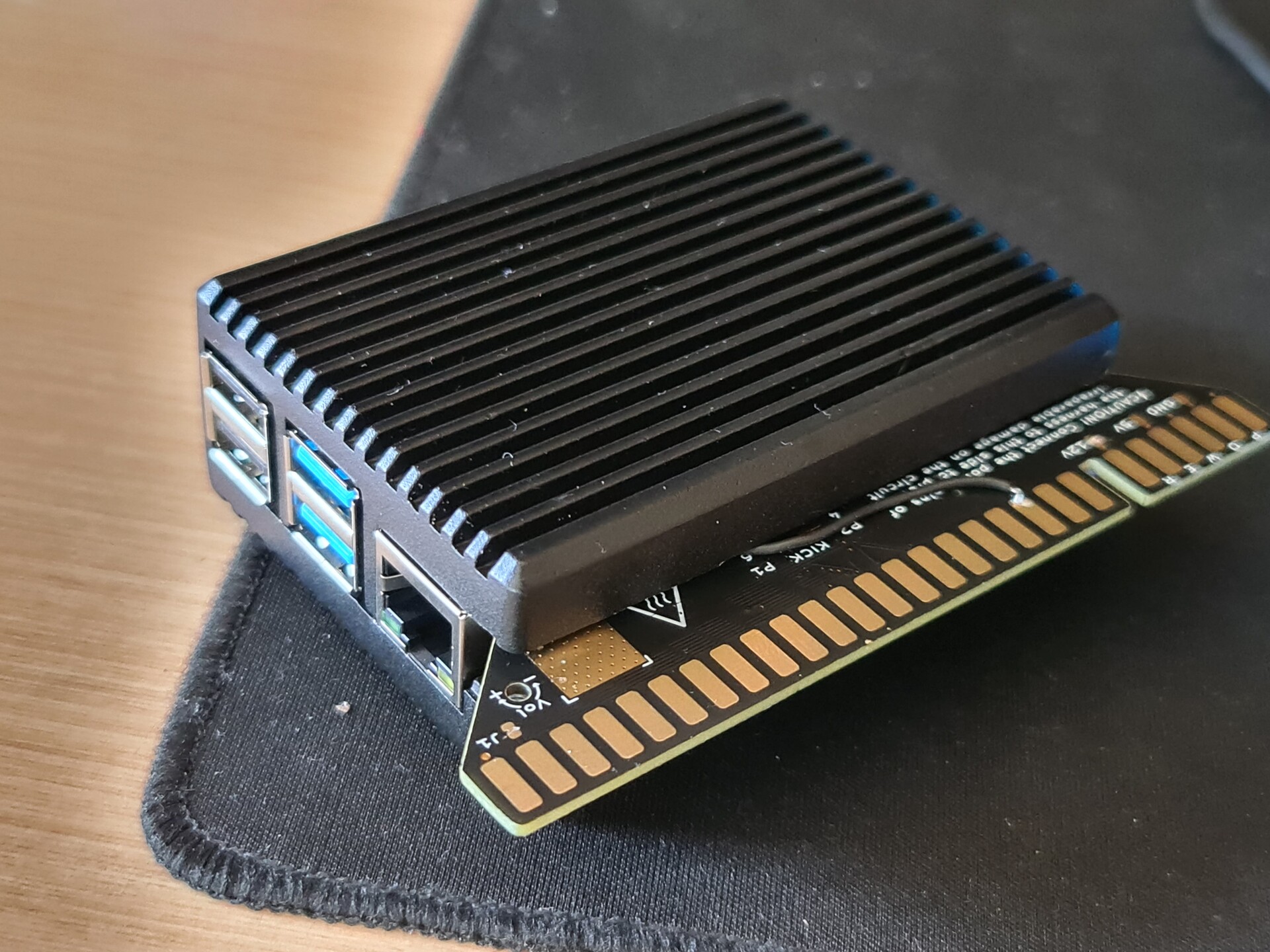
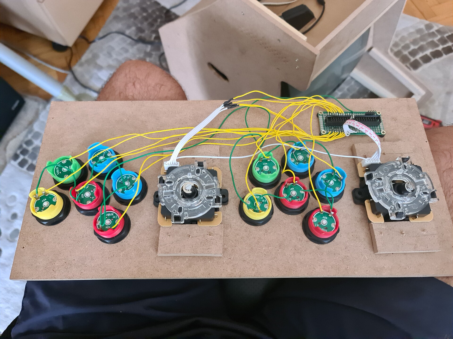
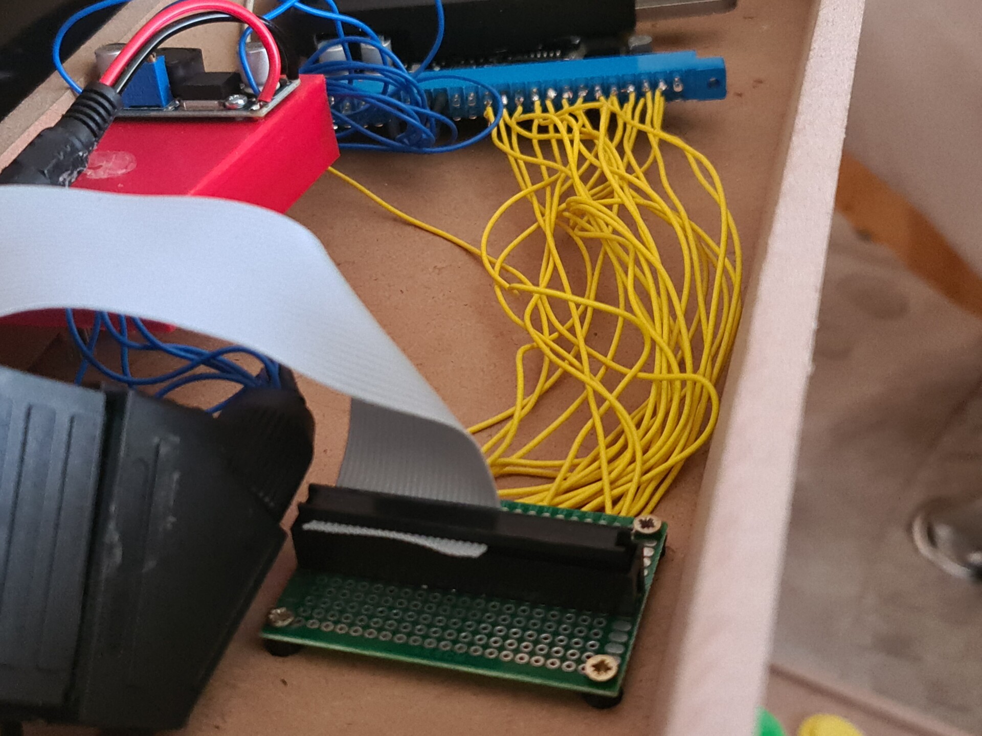
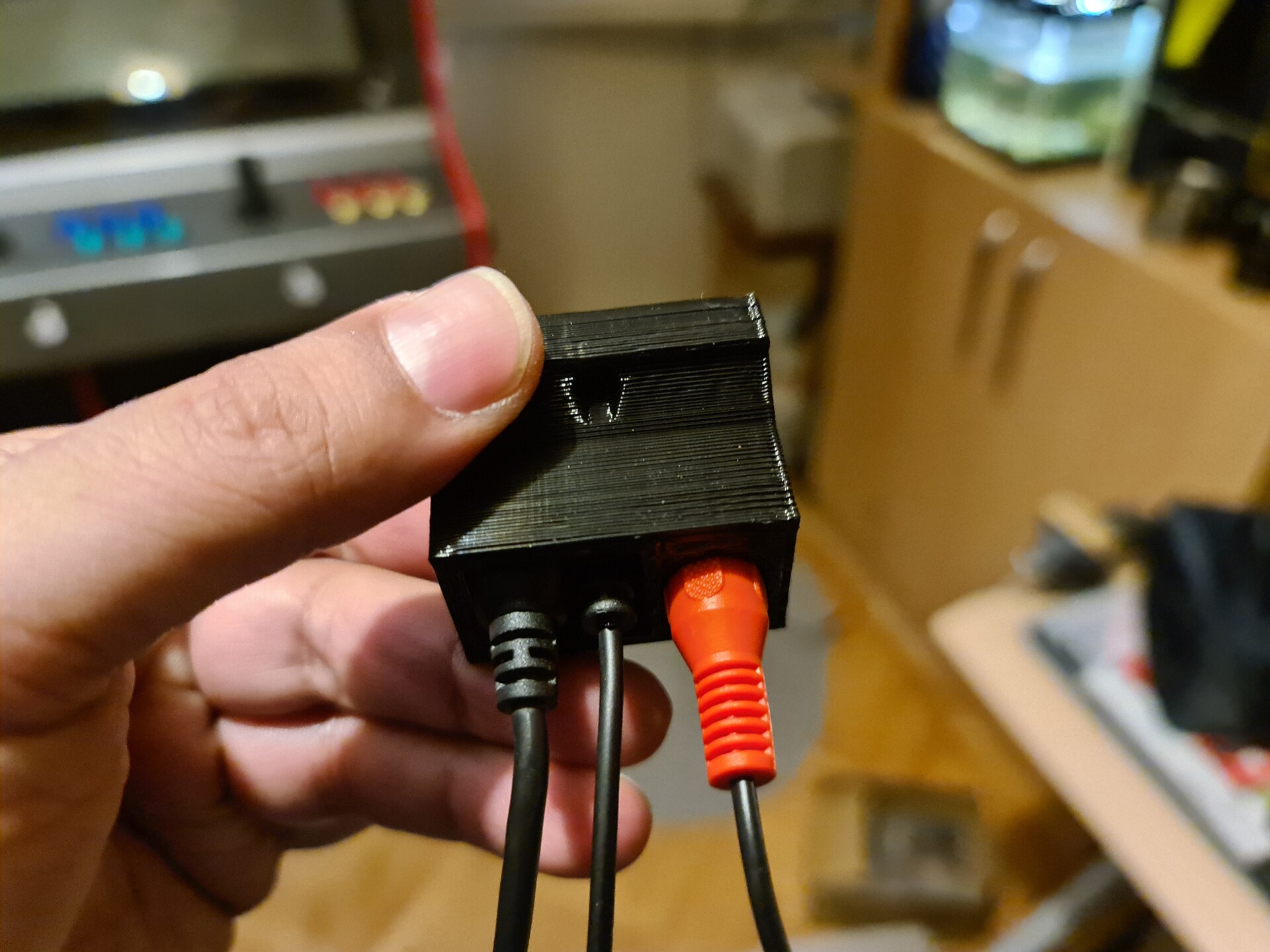
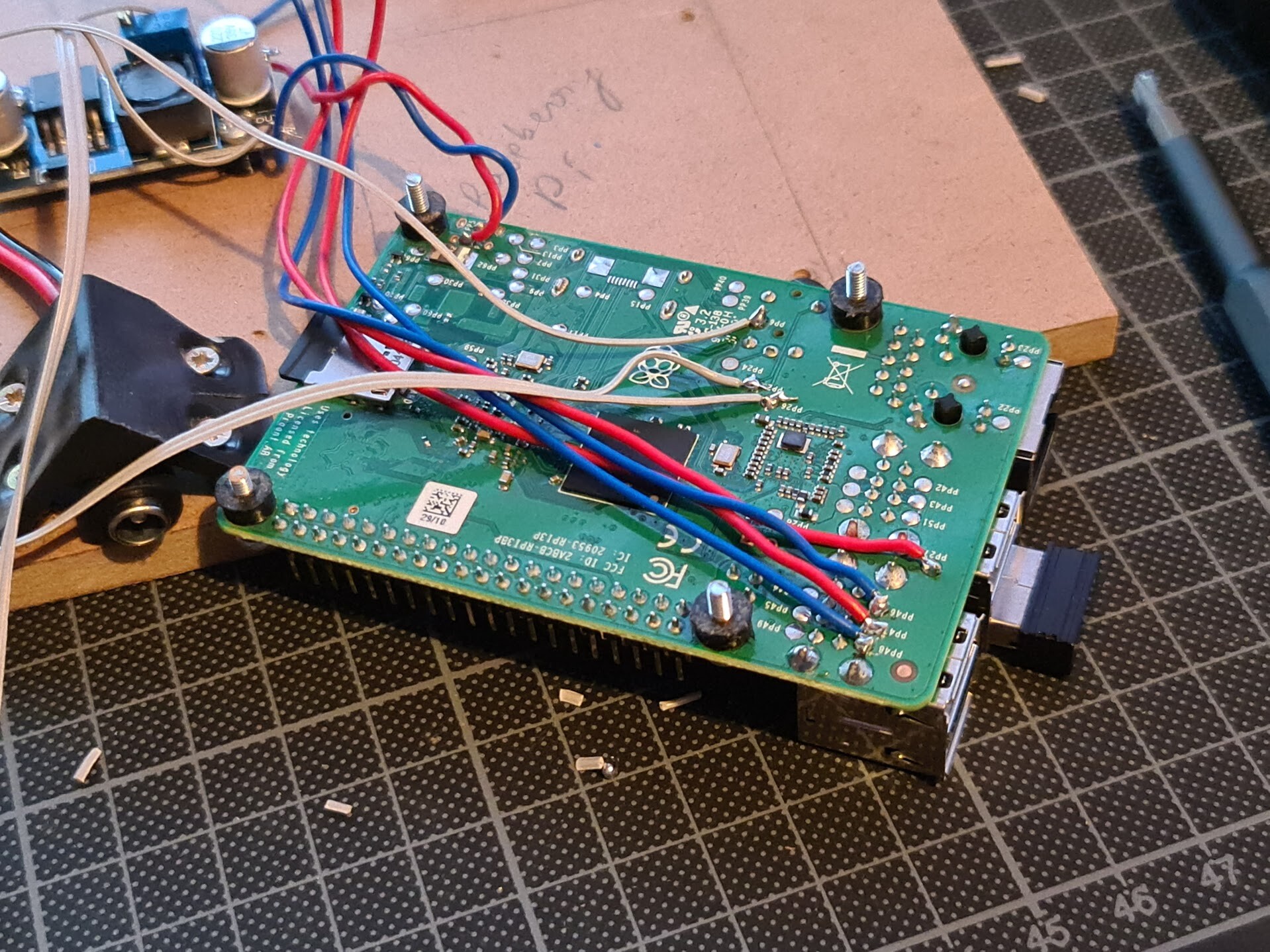
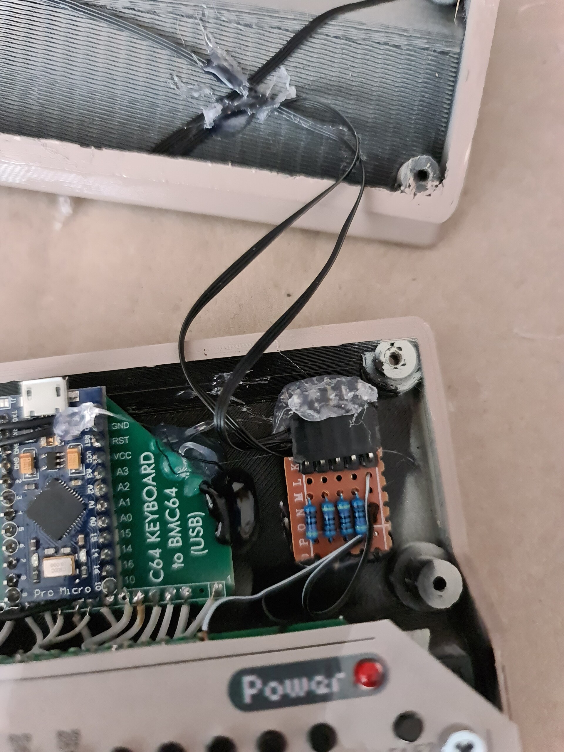
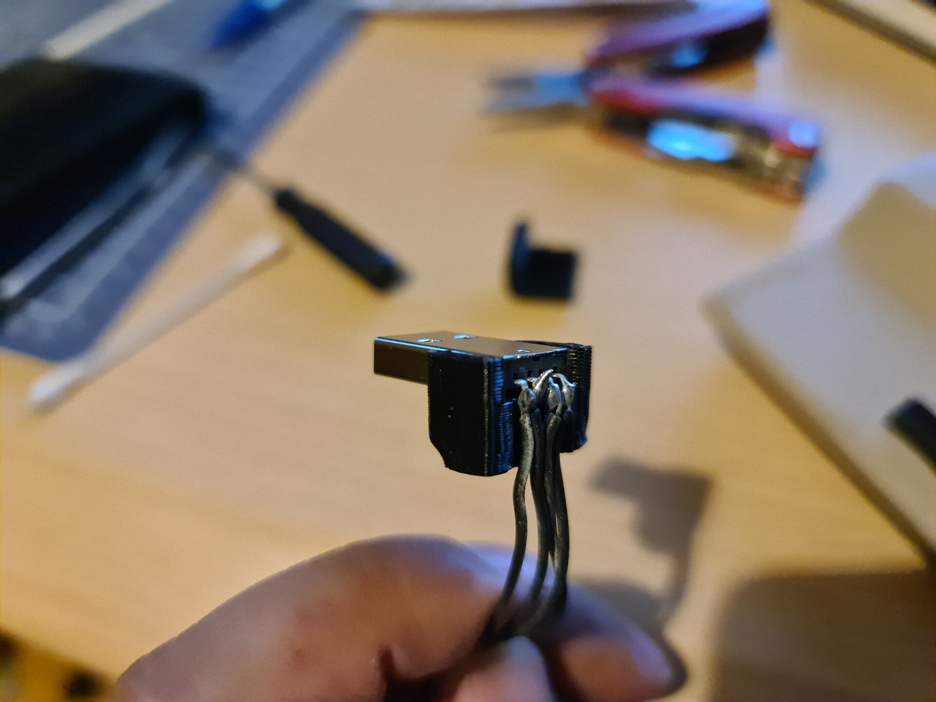
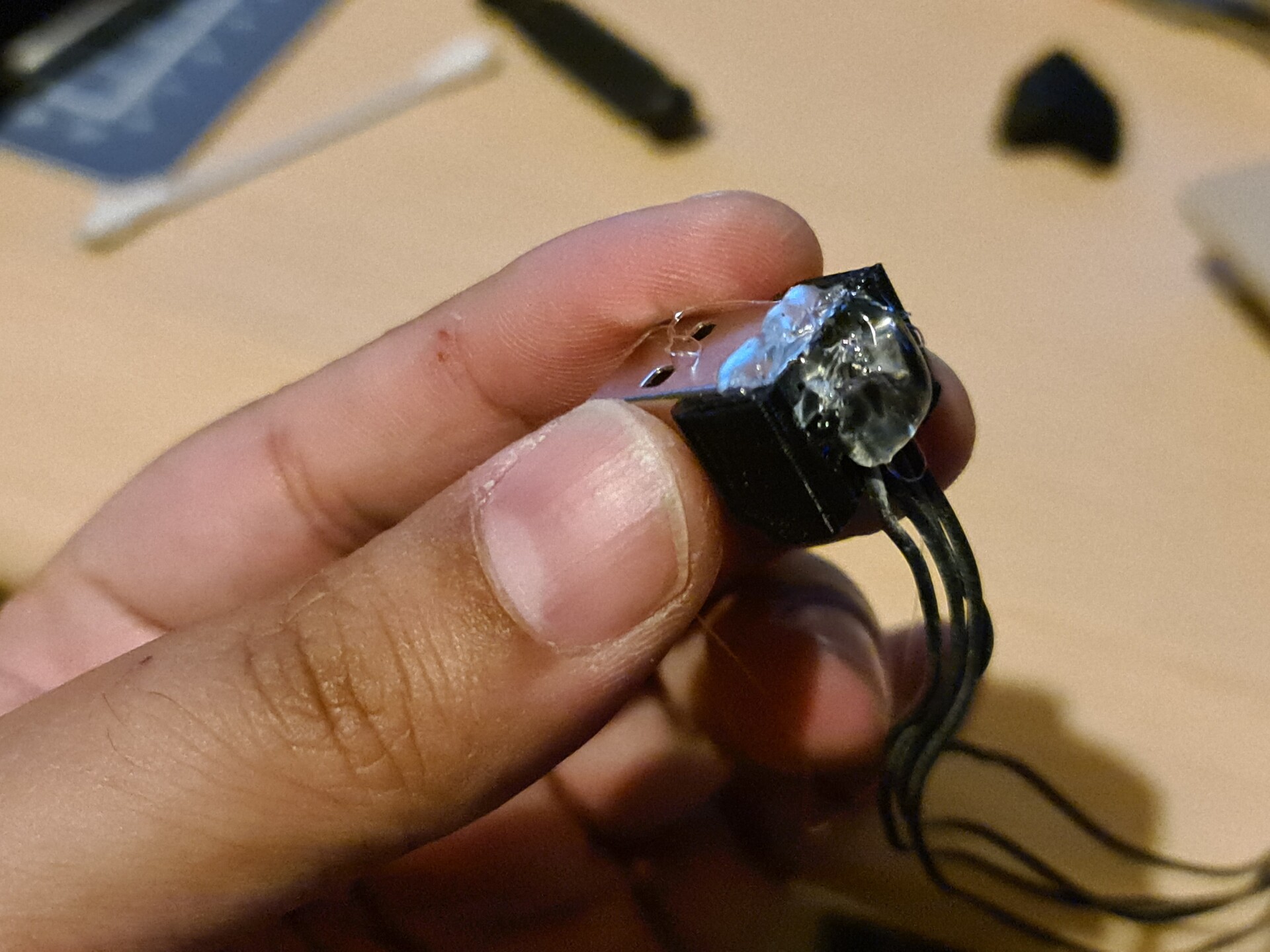
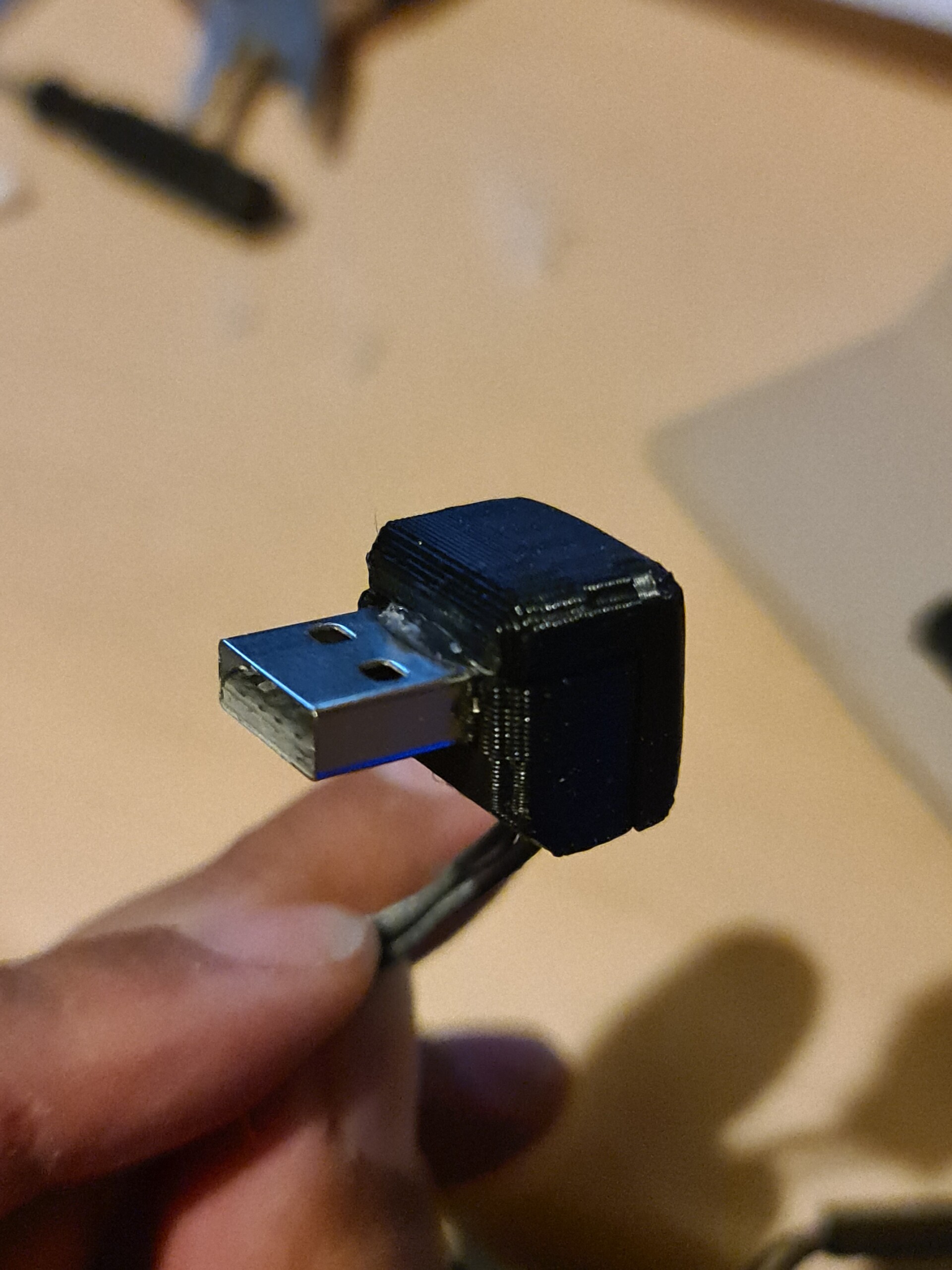
I soldered some cables to the raspberry pi for USB port, analog audio output (later I removed it), and power input, 

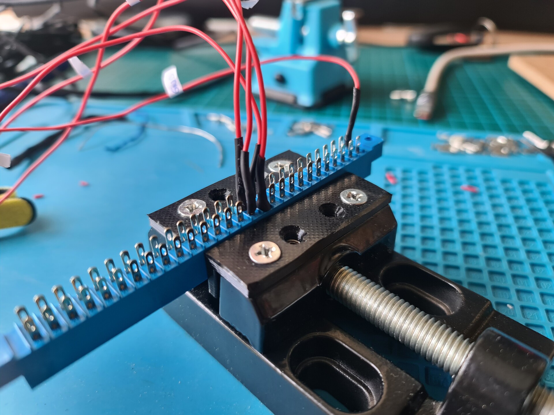
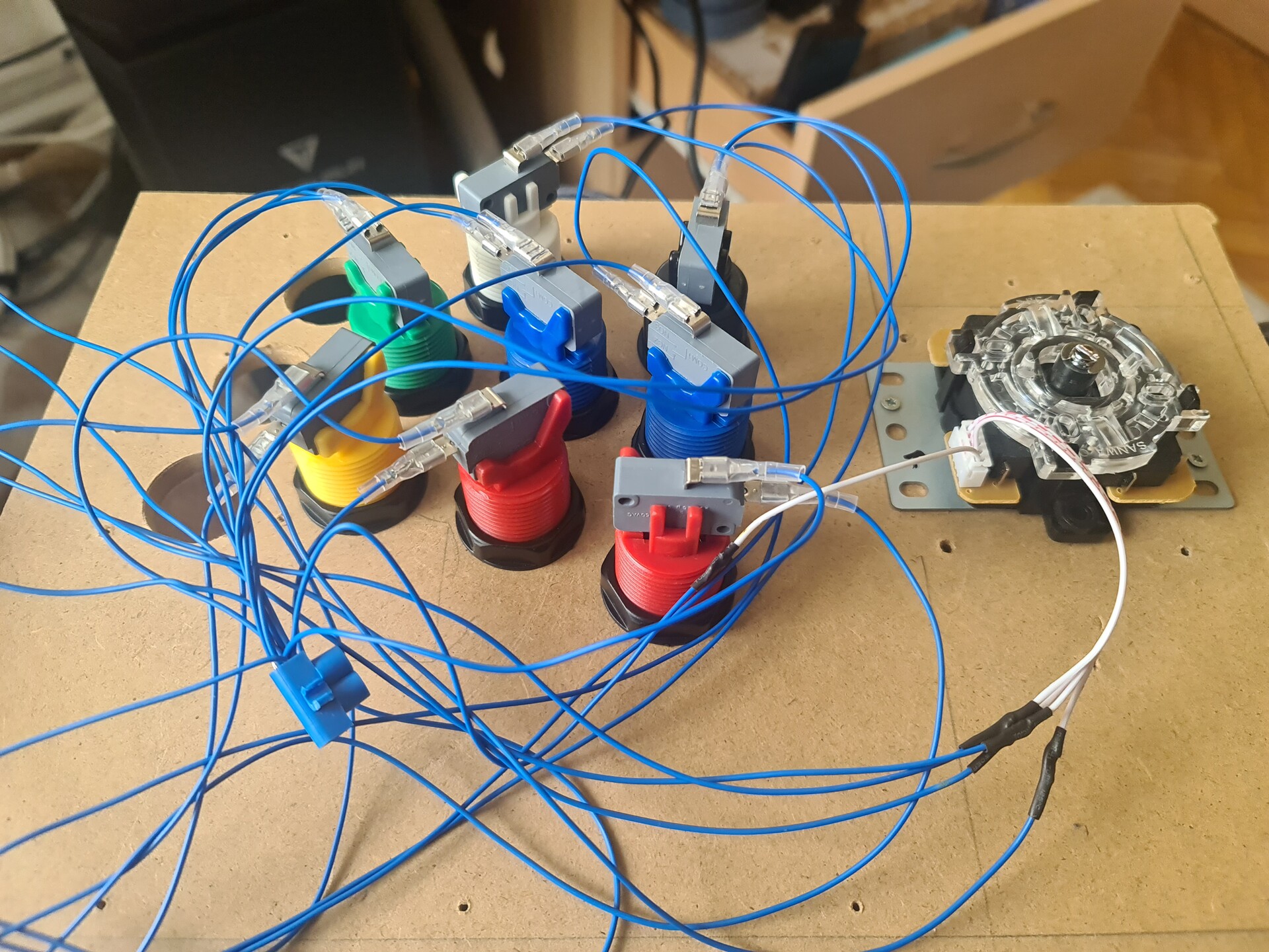
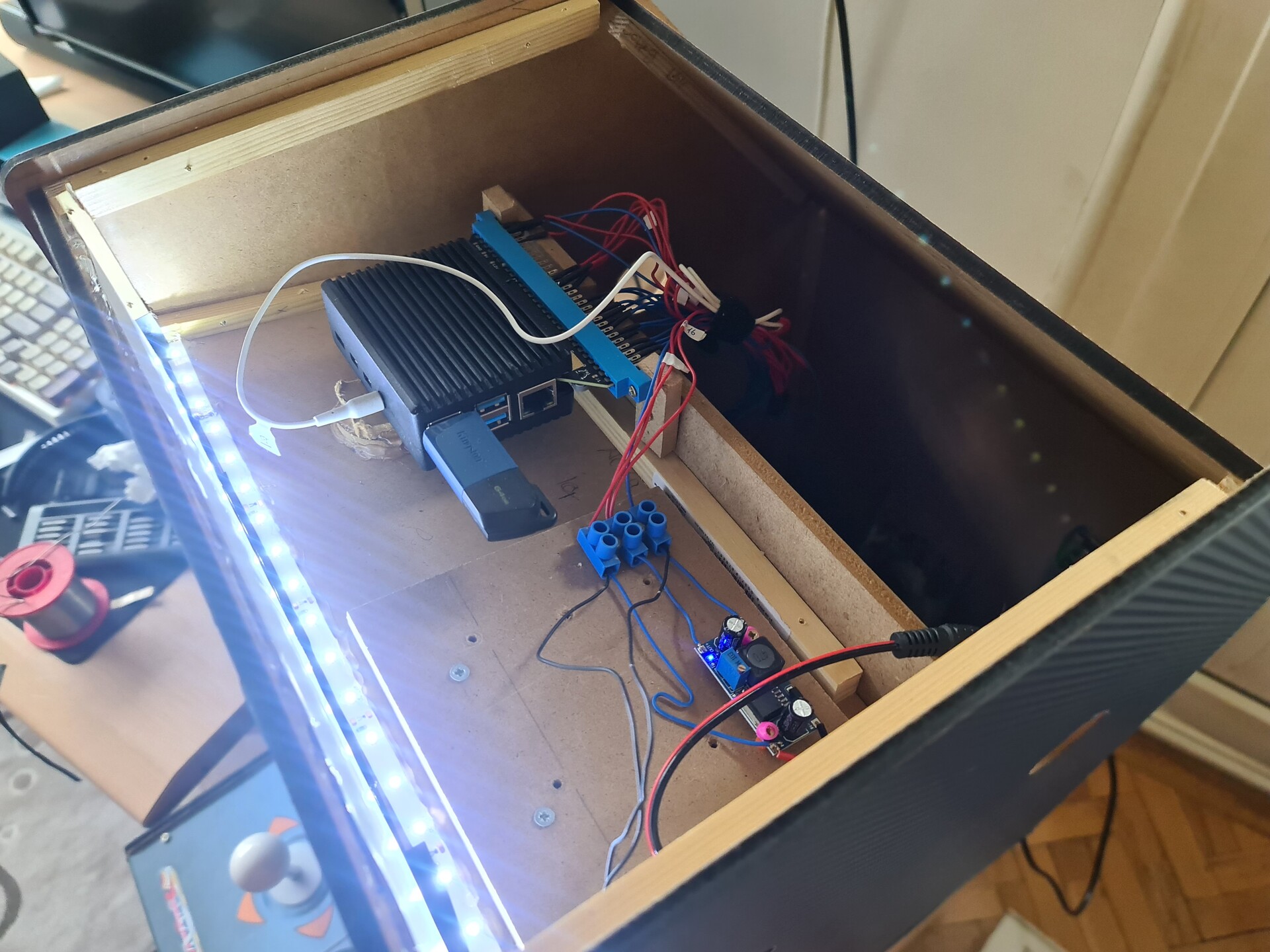
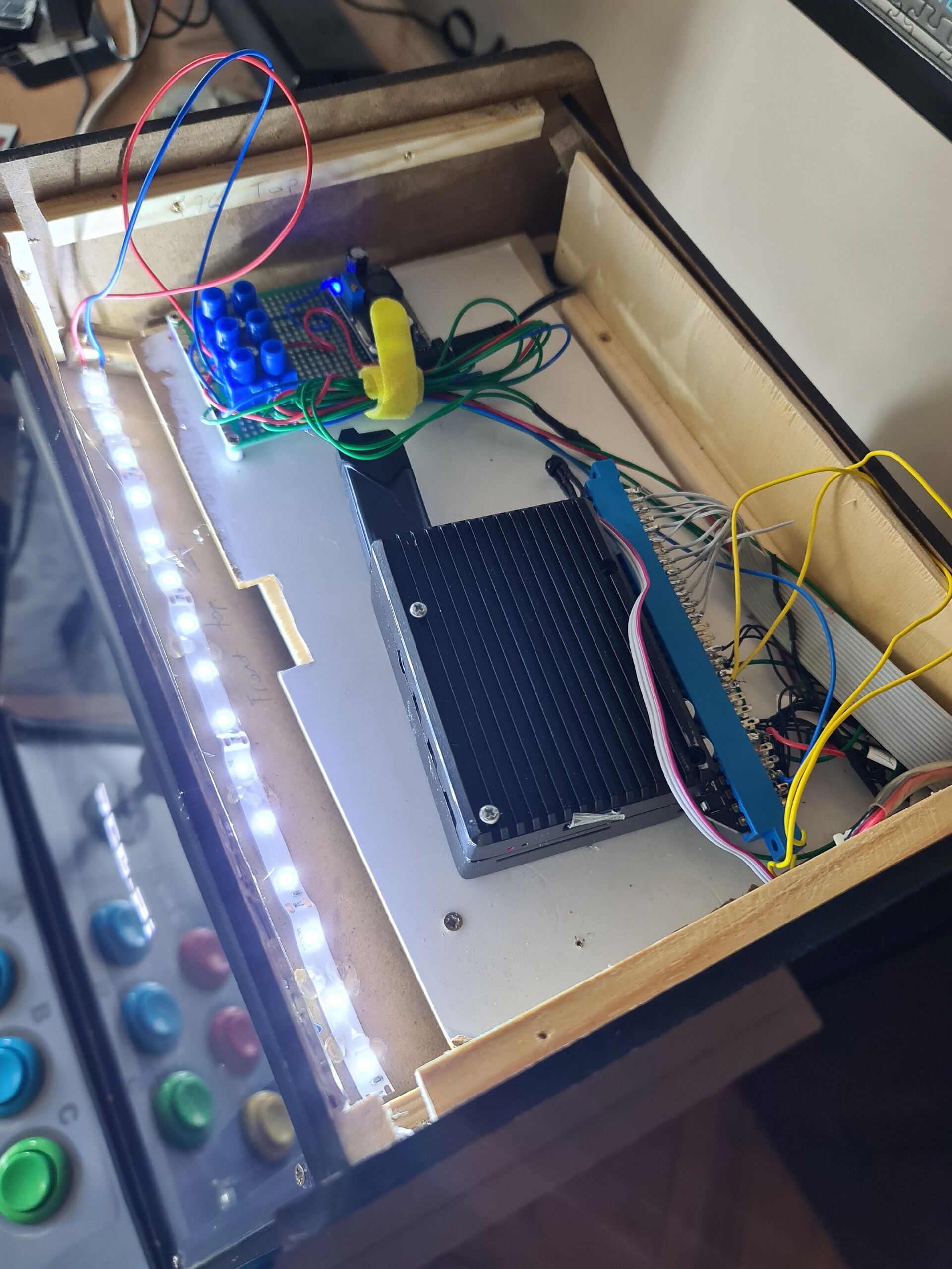
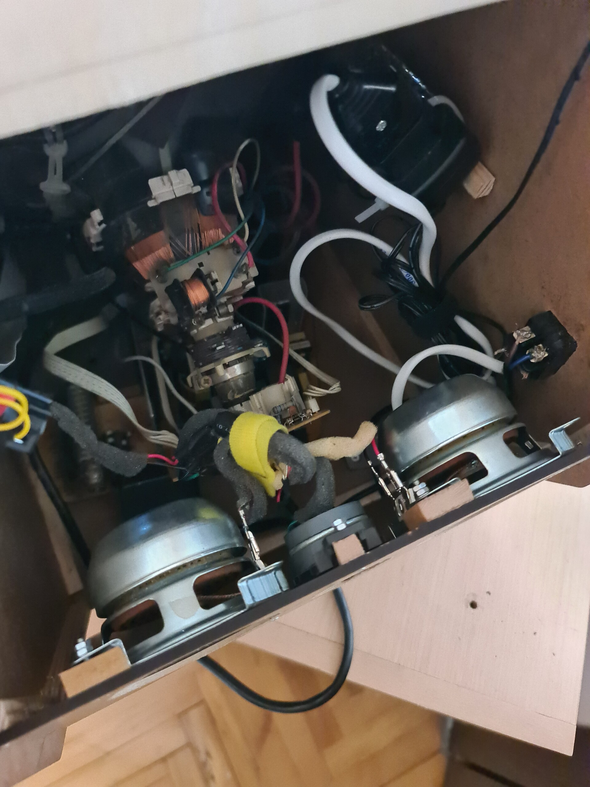
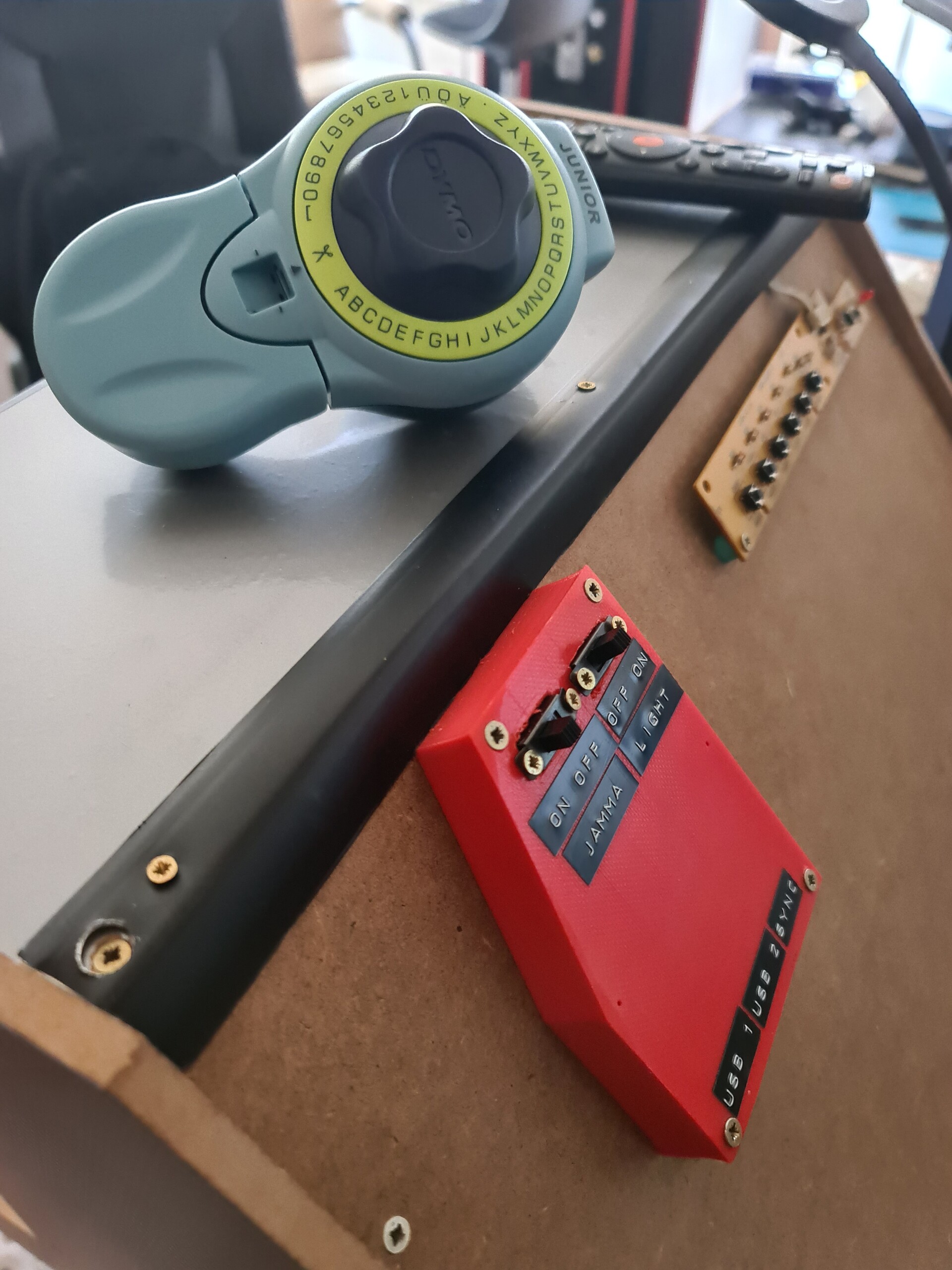
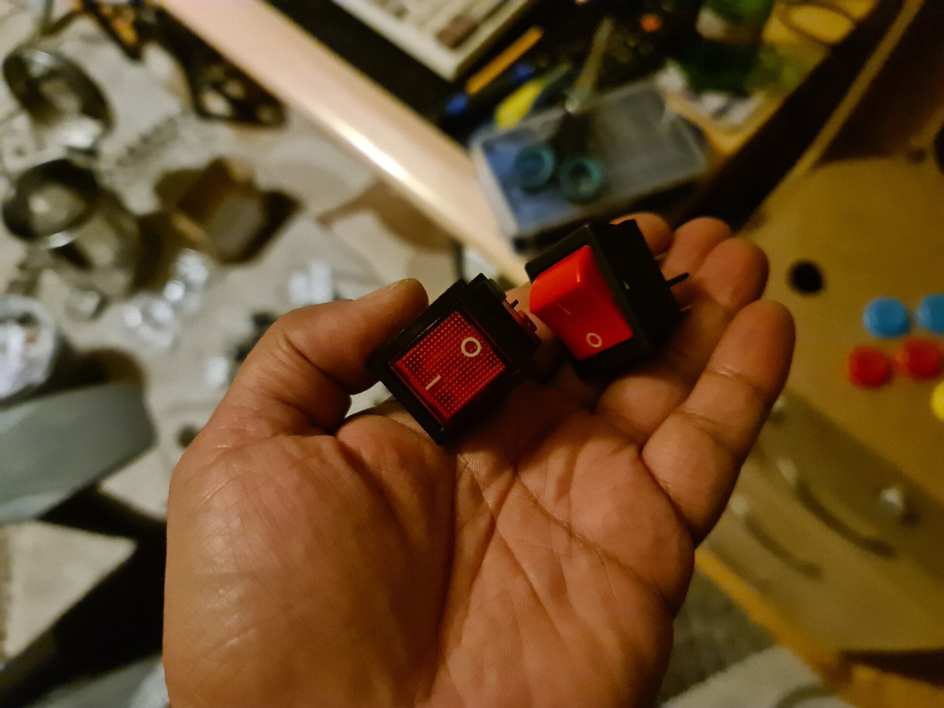
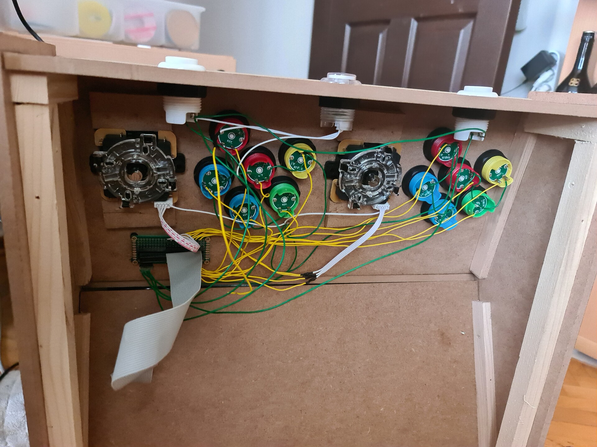
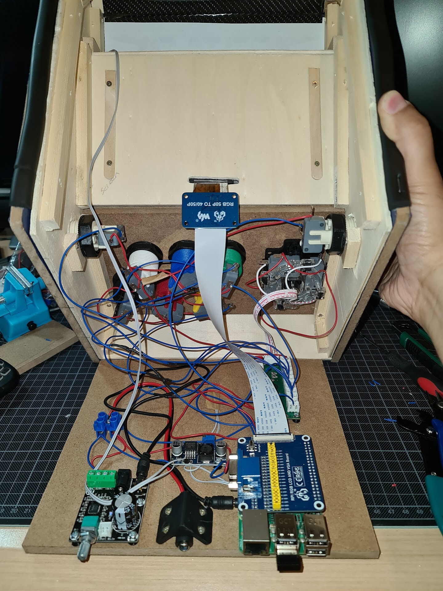
And after connecting all switches to the USB board, final electronic assembly is like this:

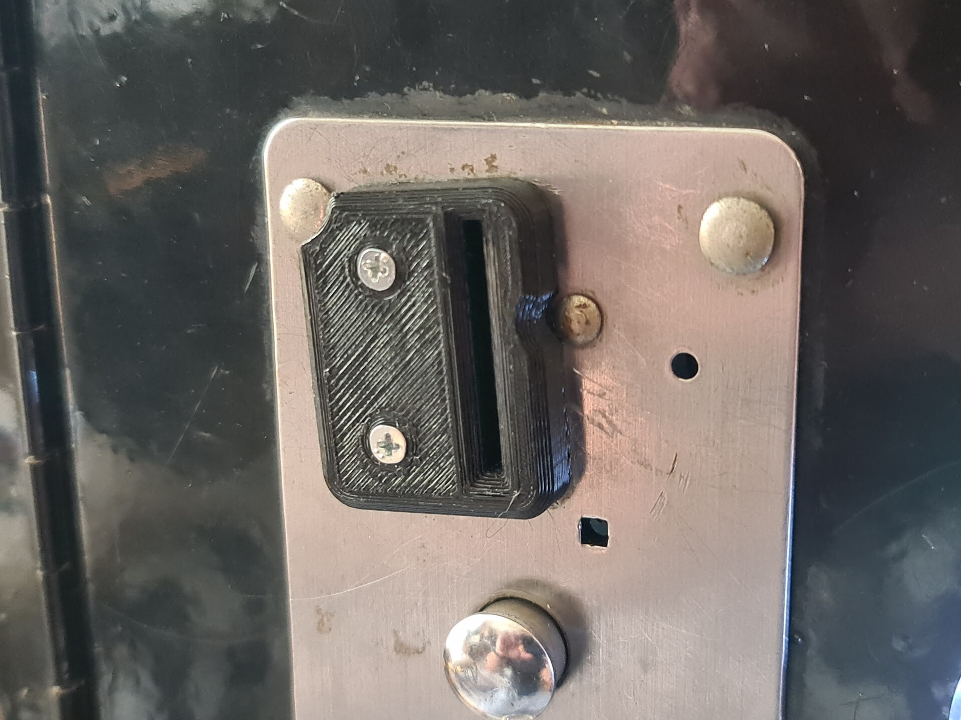
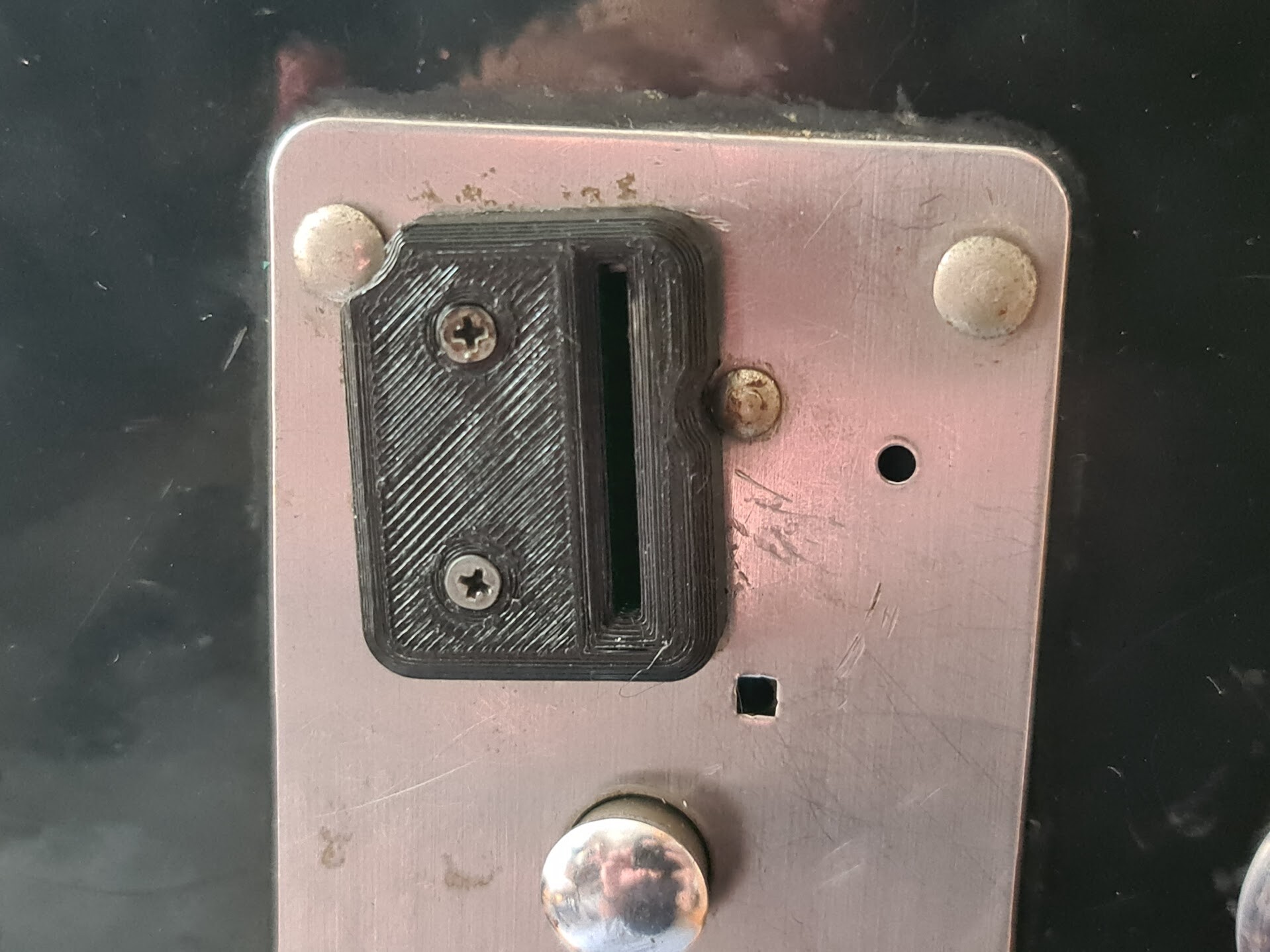
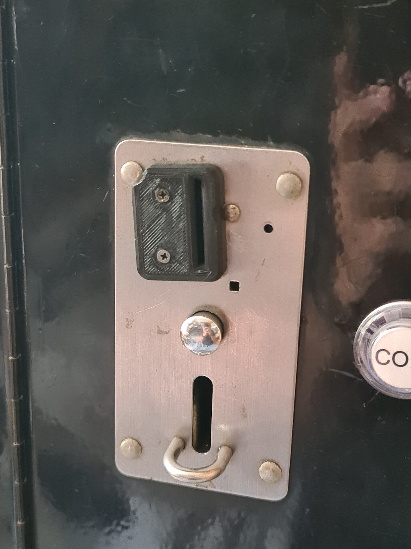
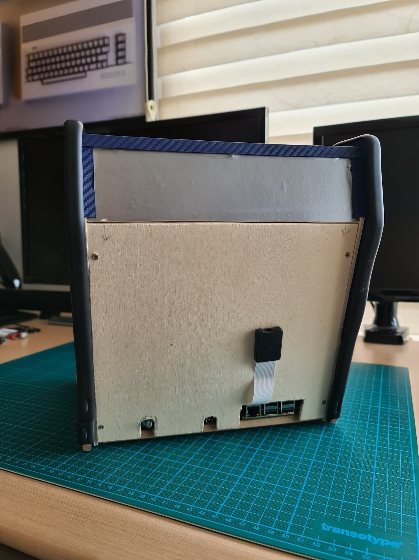
As a final addition, I put an SD card extension cable for accessing the SD card easily.

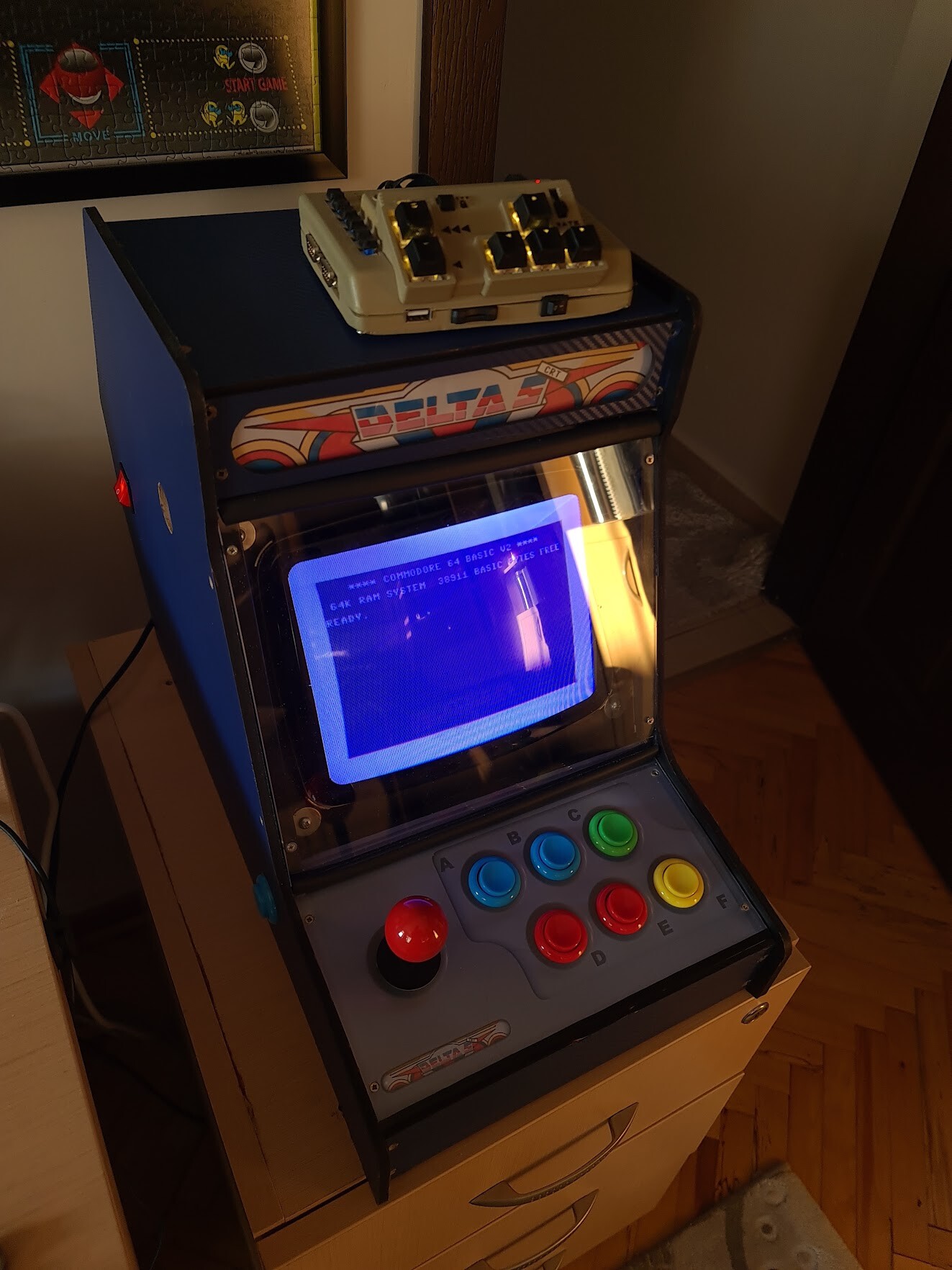
Looks like a cyberpunk B-movie set from 90s :)

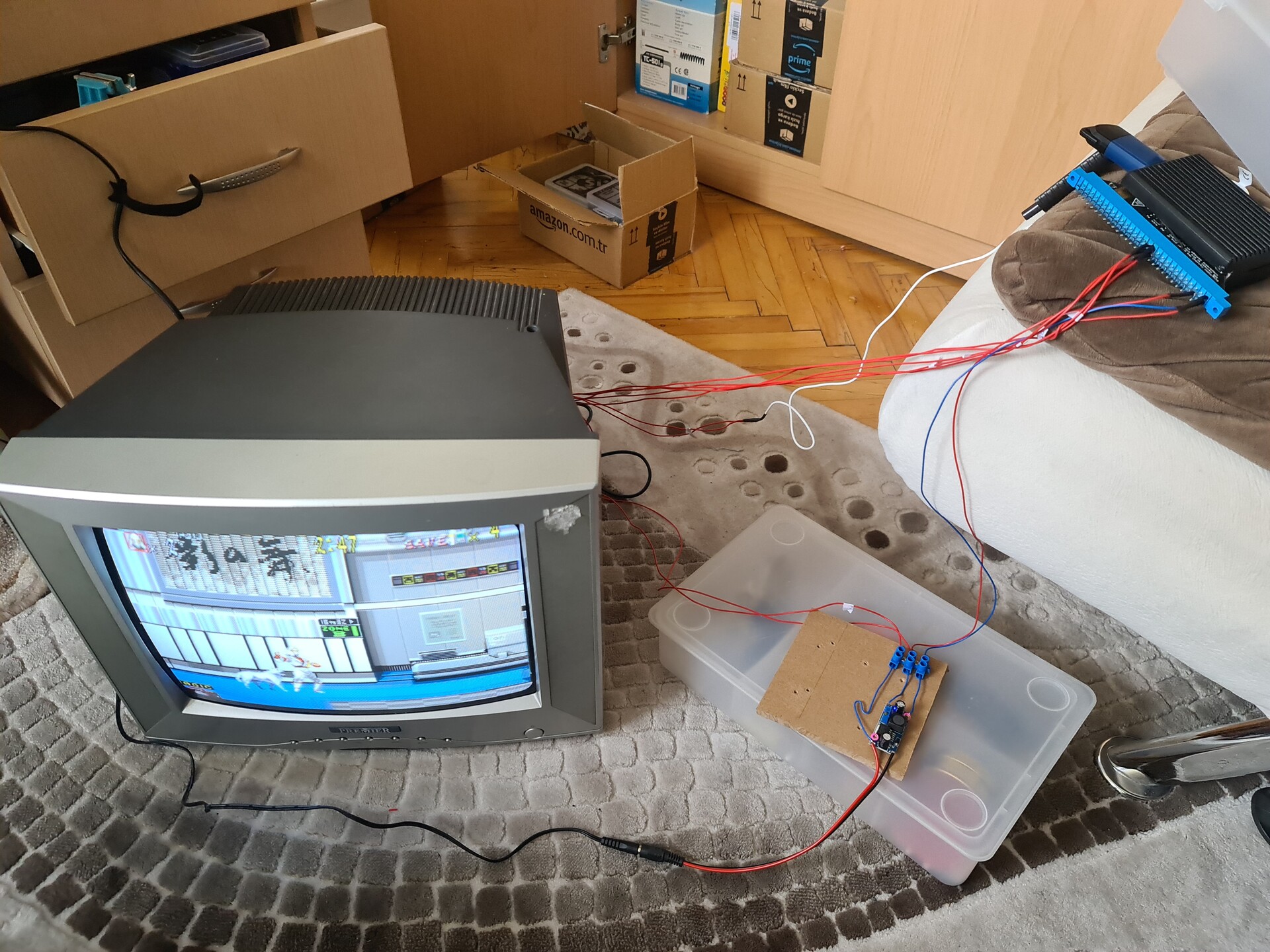
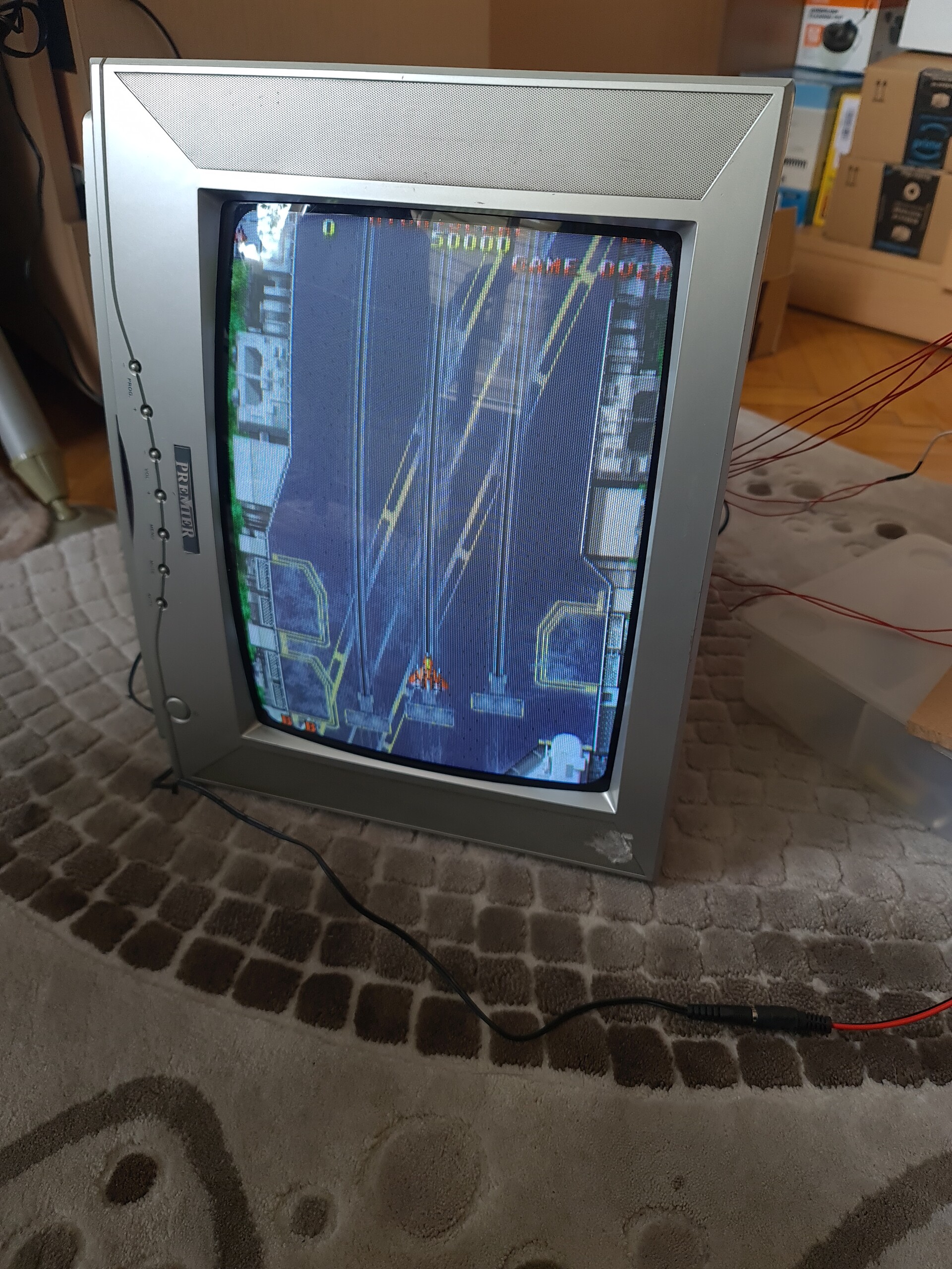
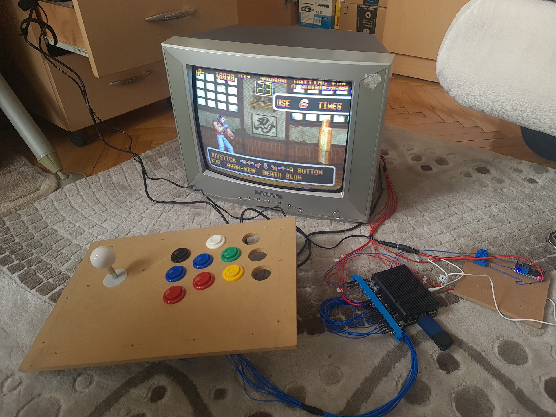
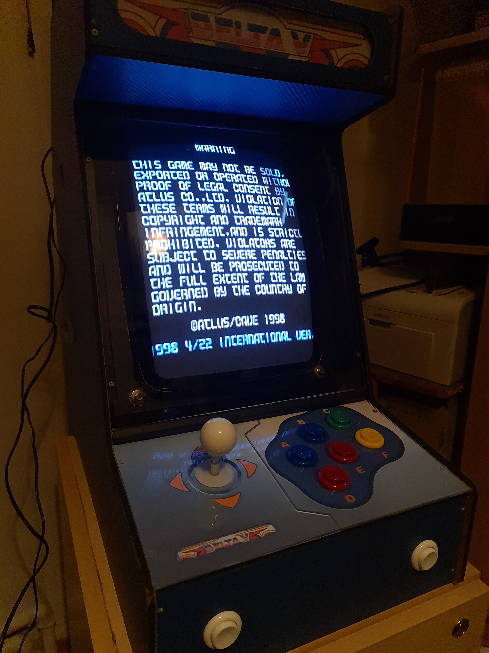
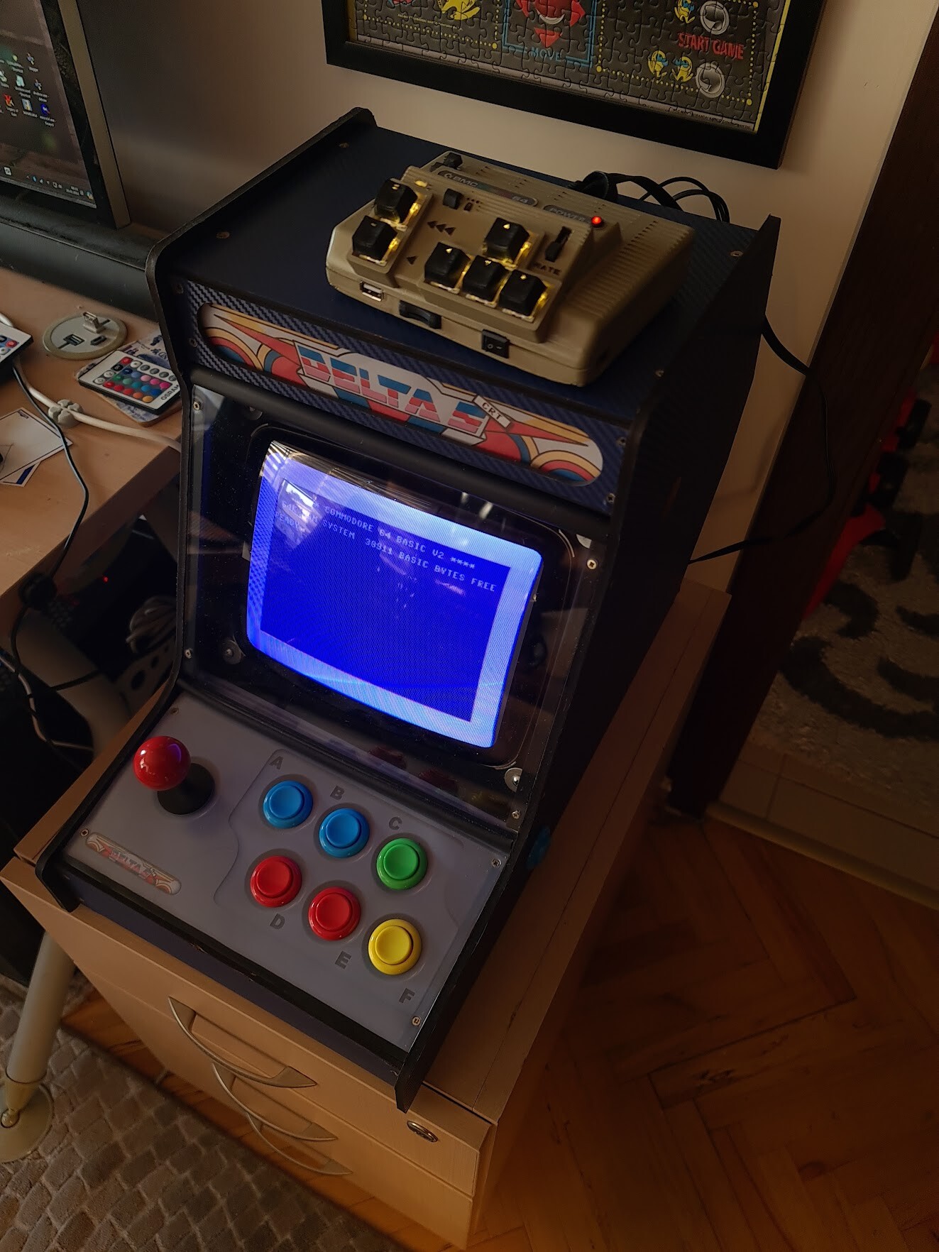
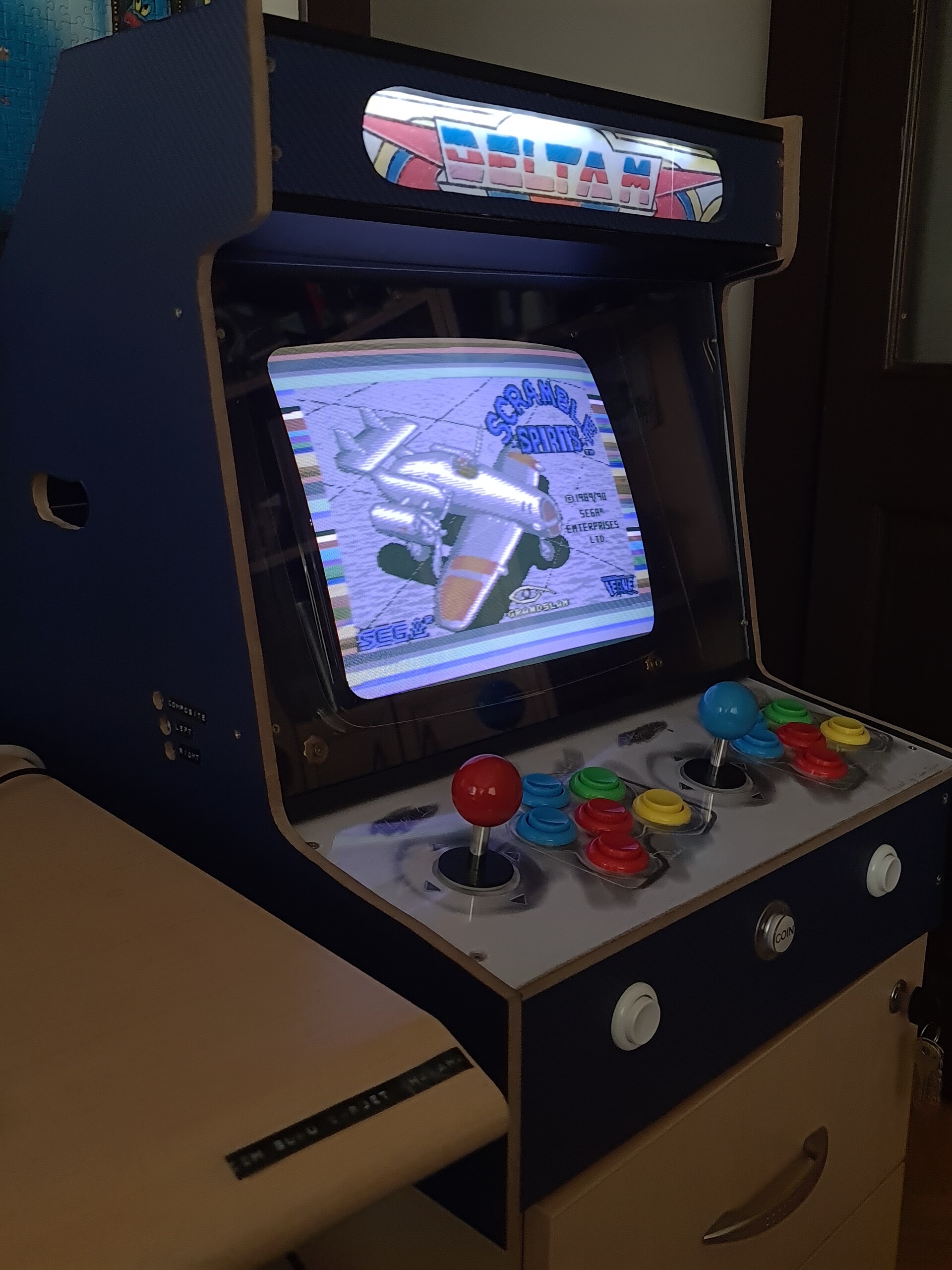
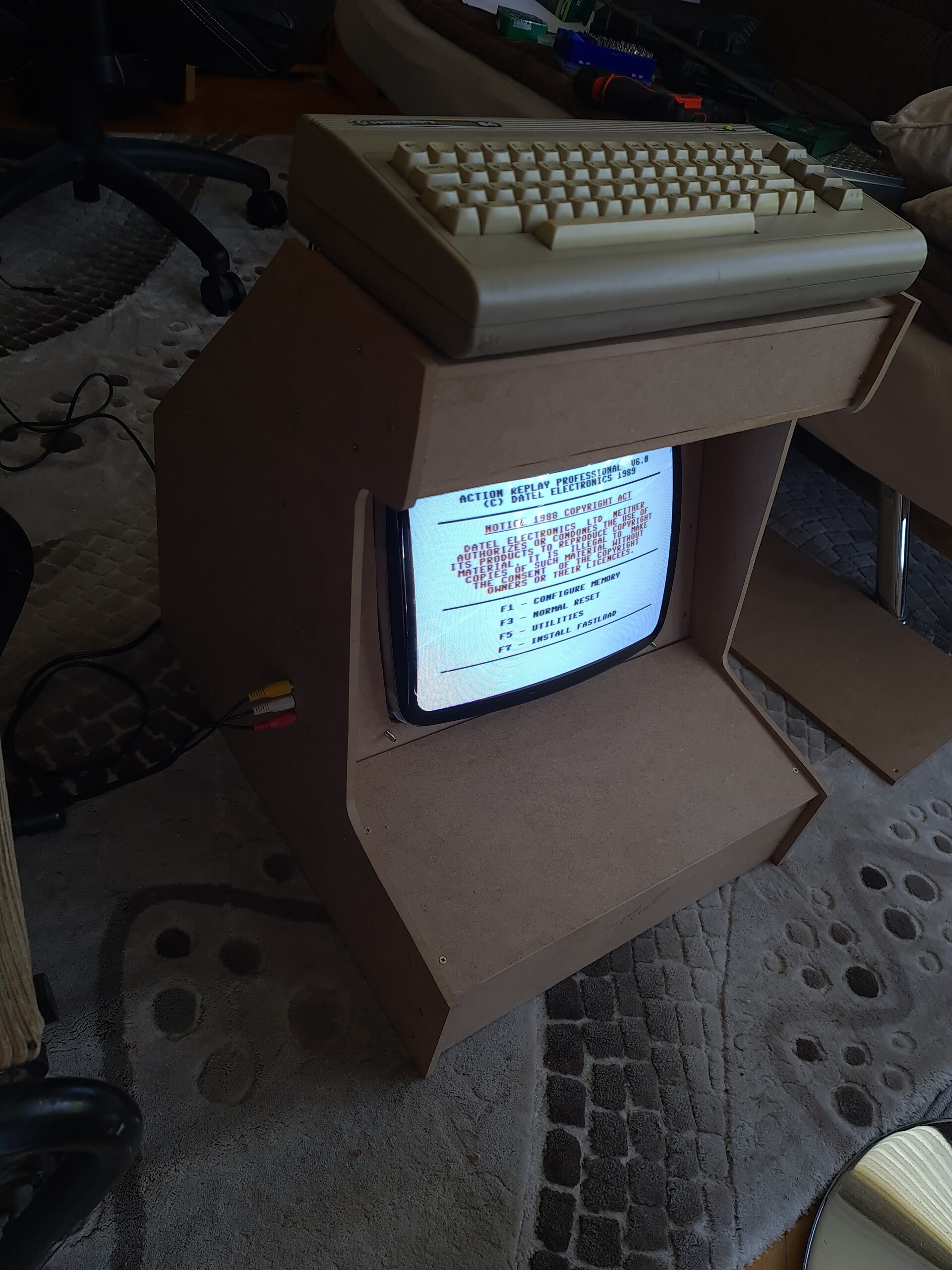
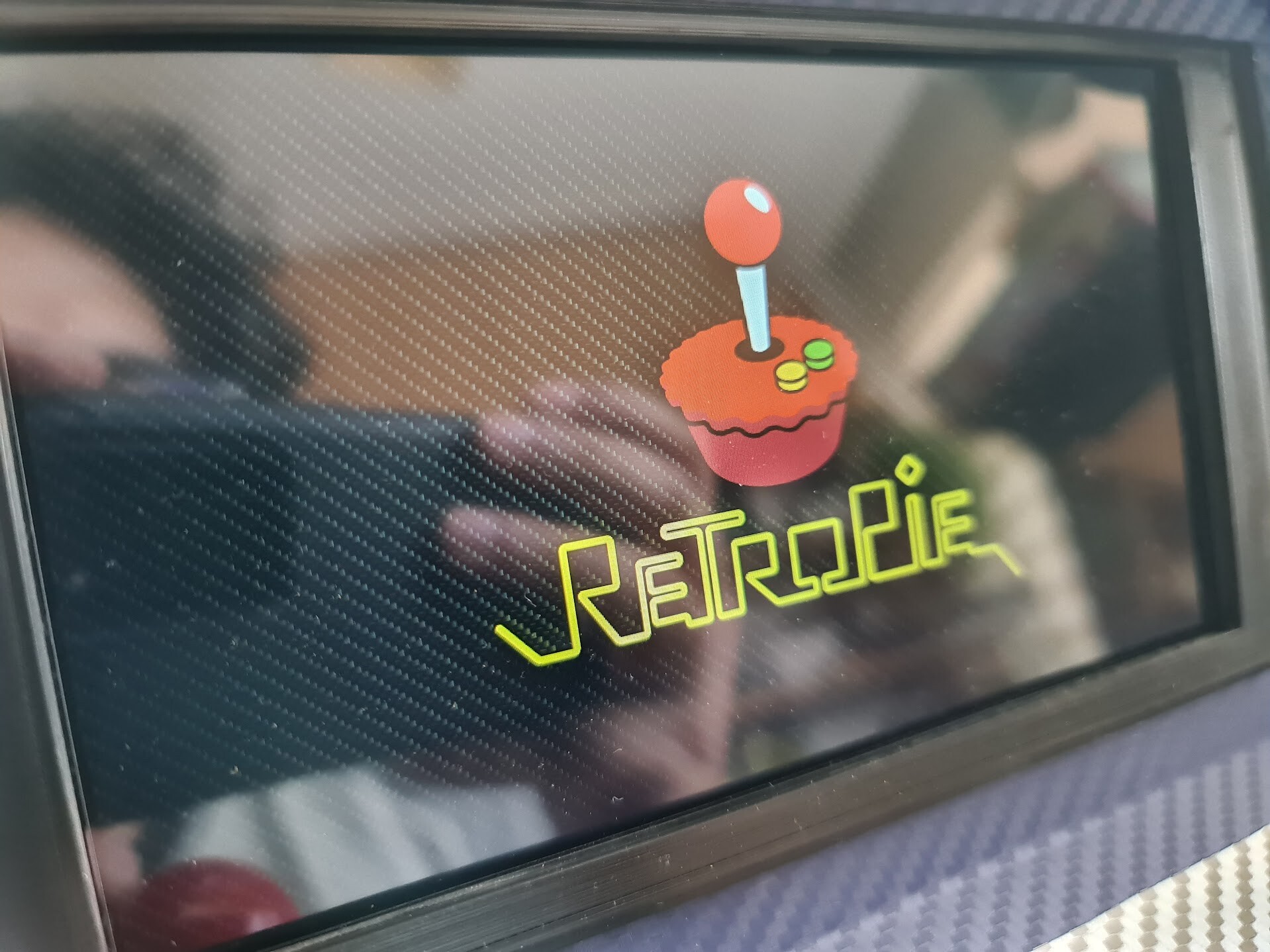
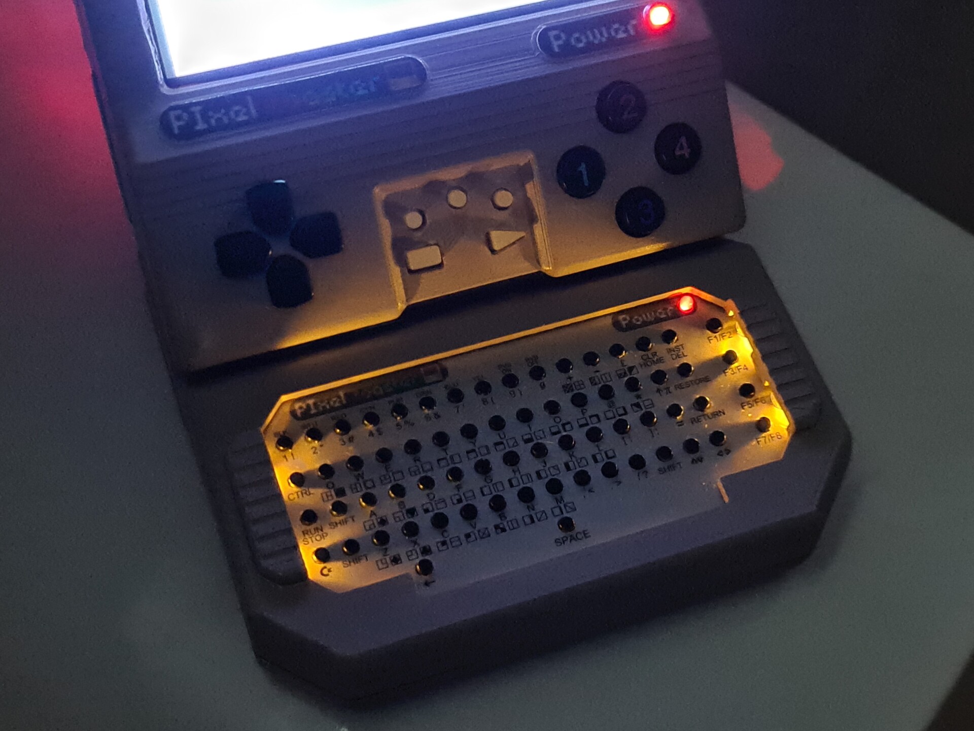
Finally I can test the machine. 

This is Retropie loading screen. There is a good match about the "carbon texture" choice I made on the sticker foils :)

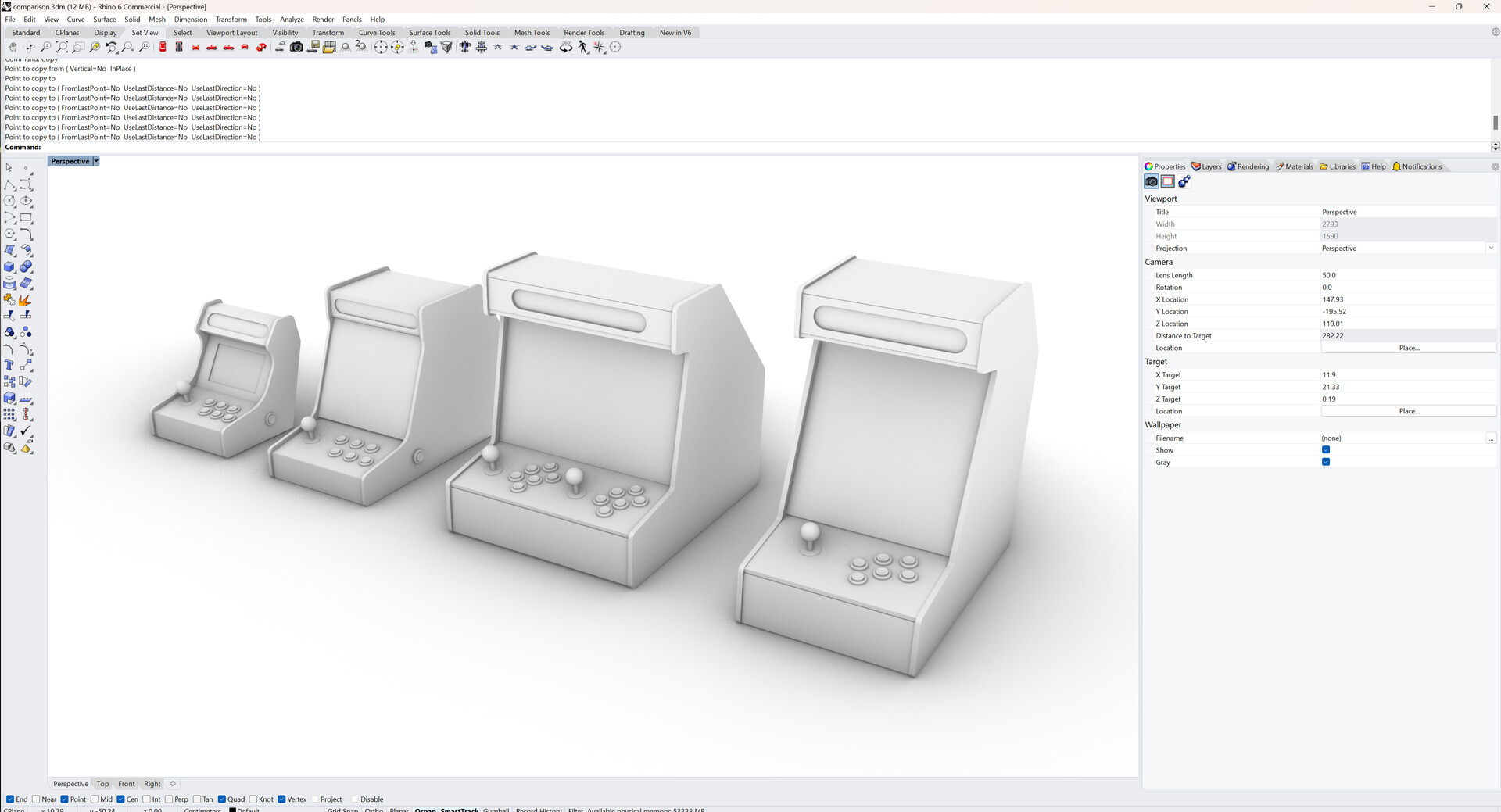
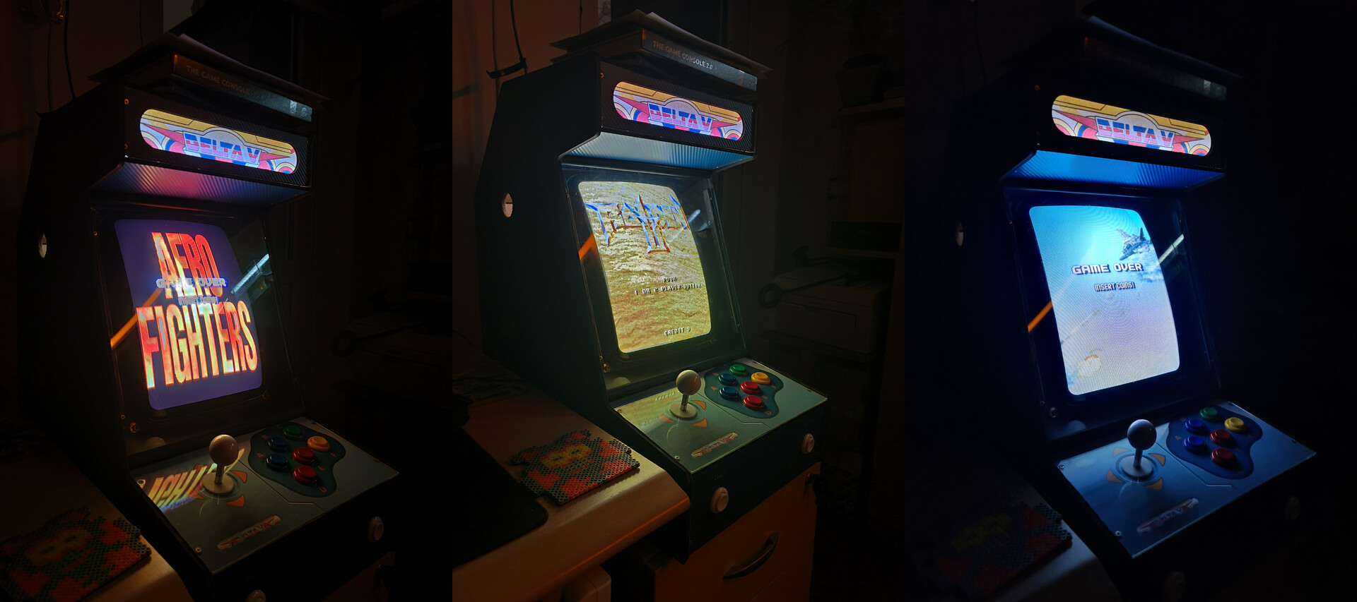
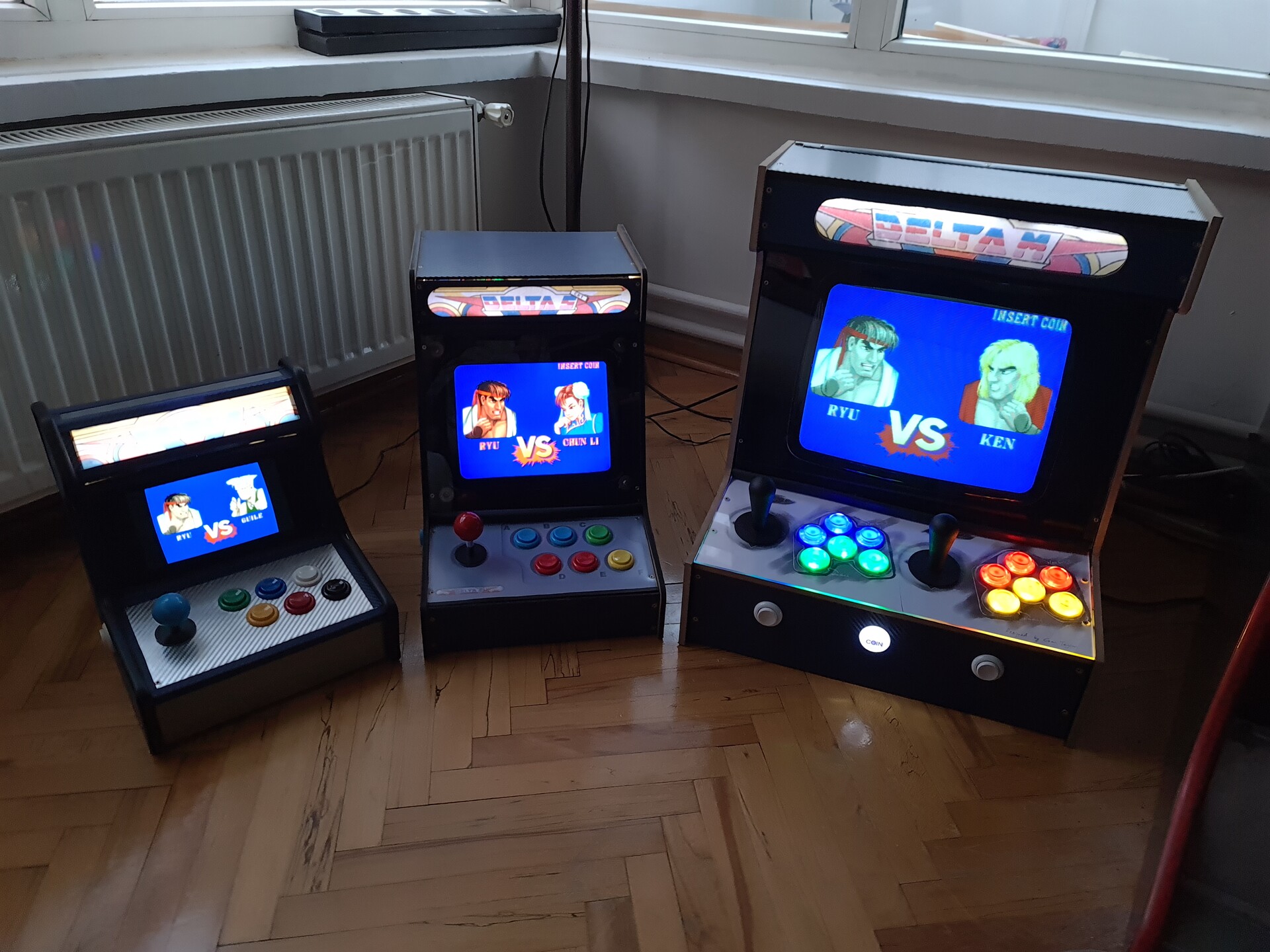
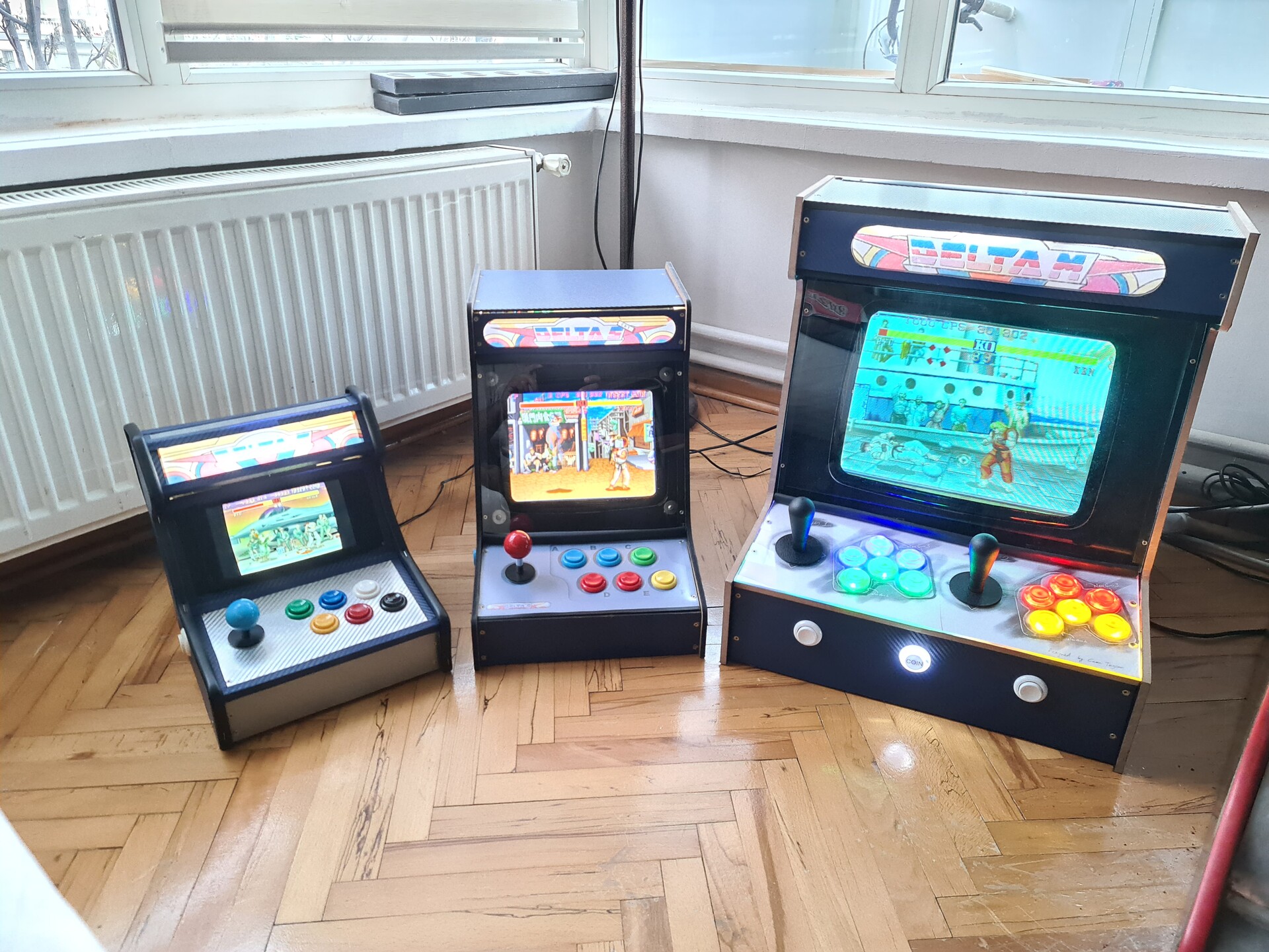
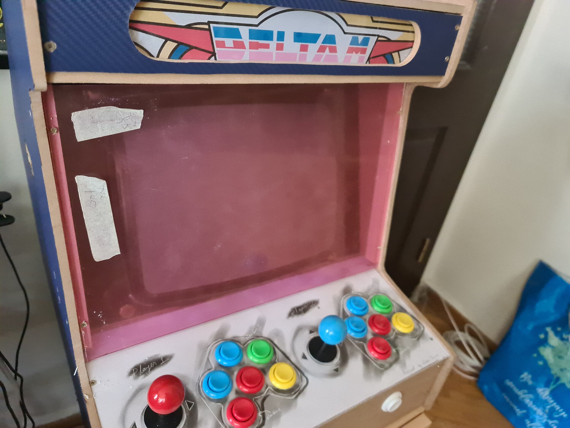
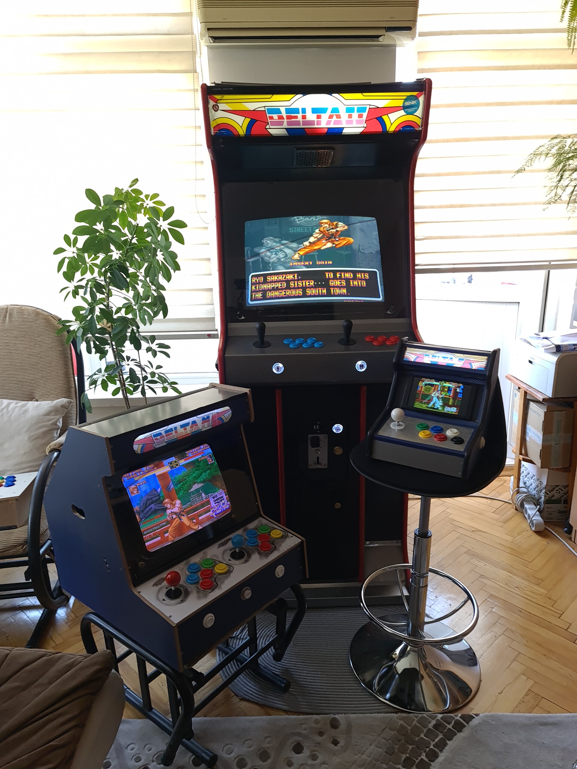
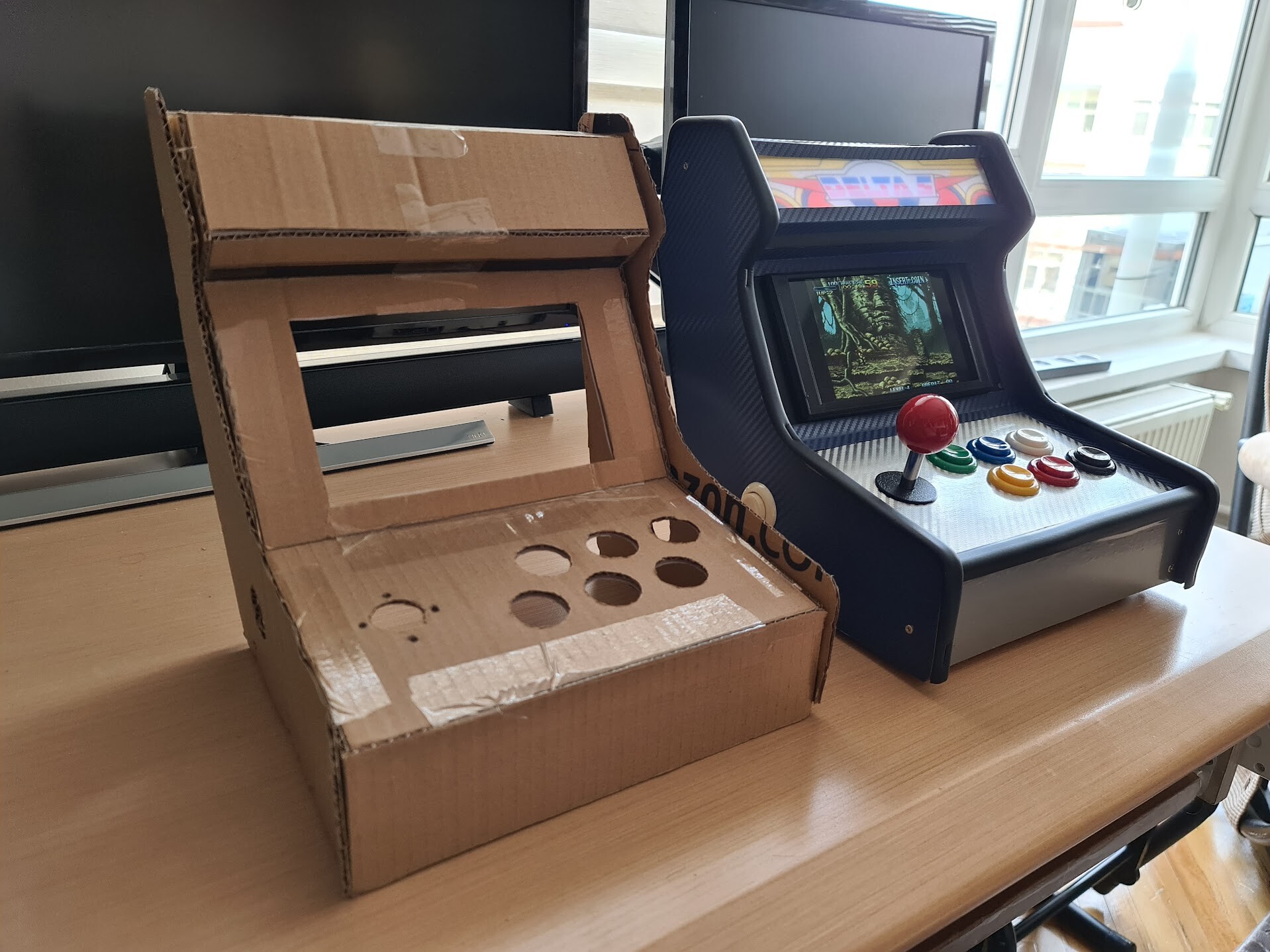
A comparison with the draft and final product!

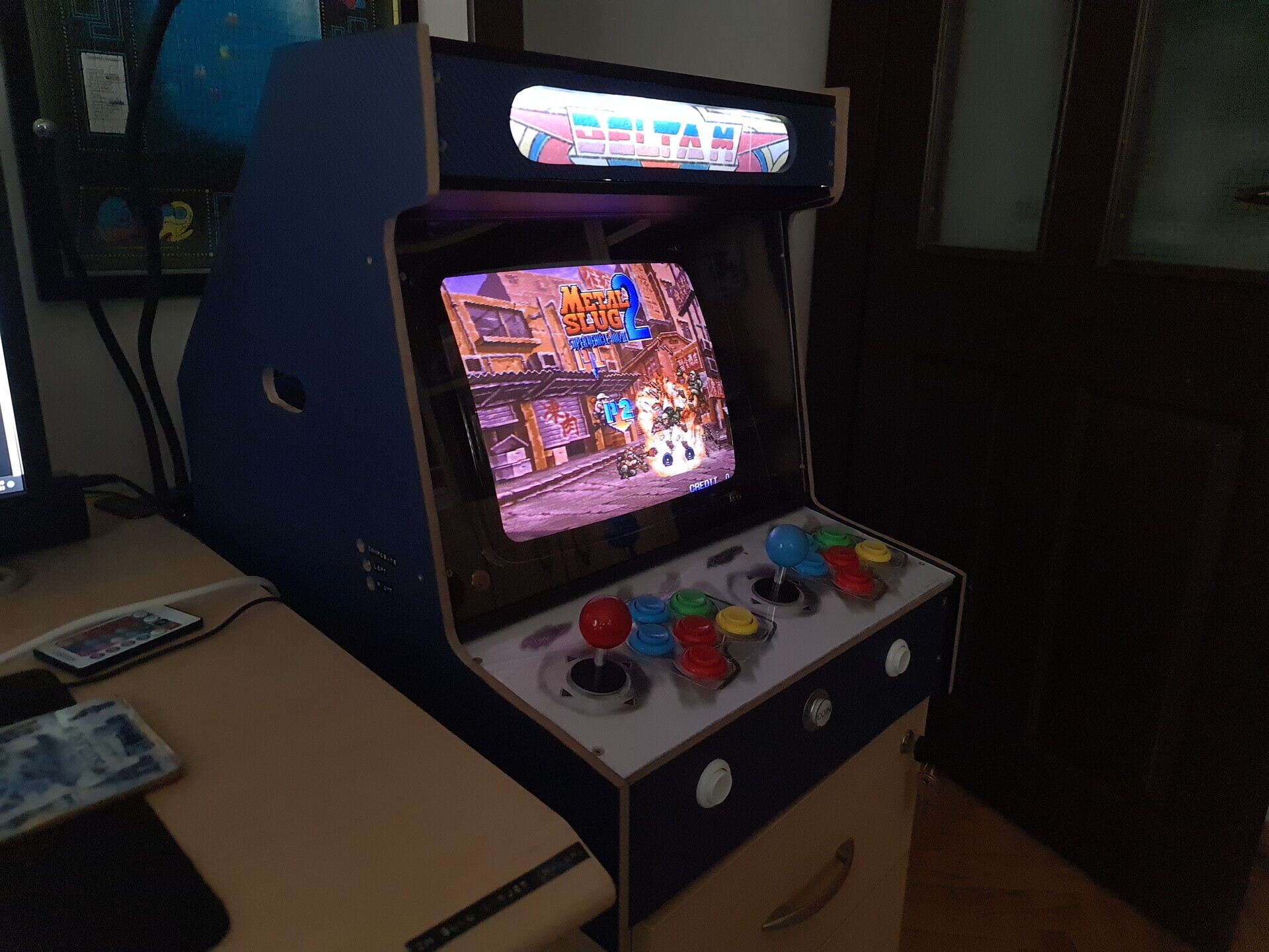
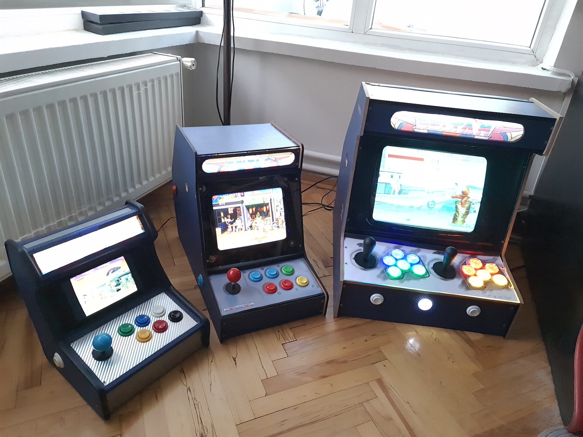
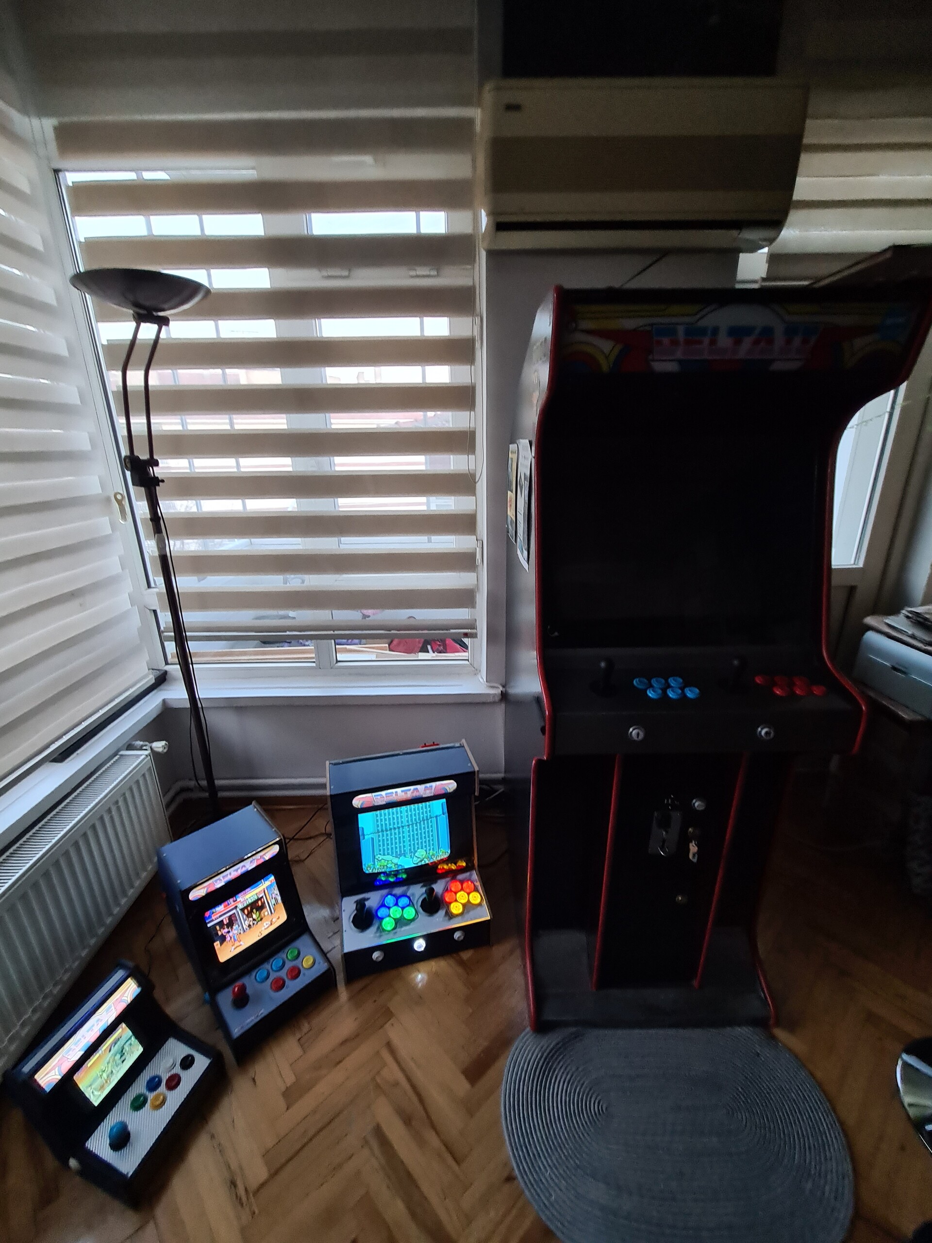
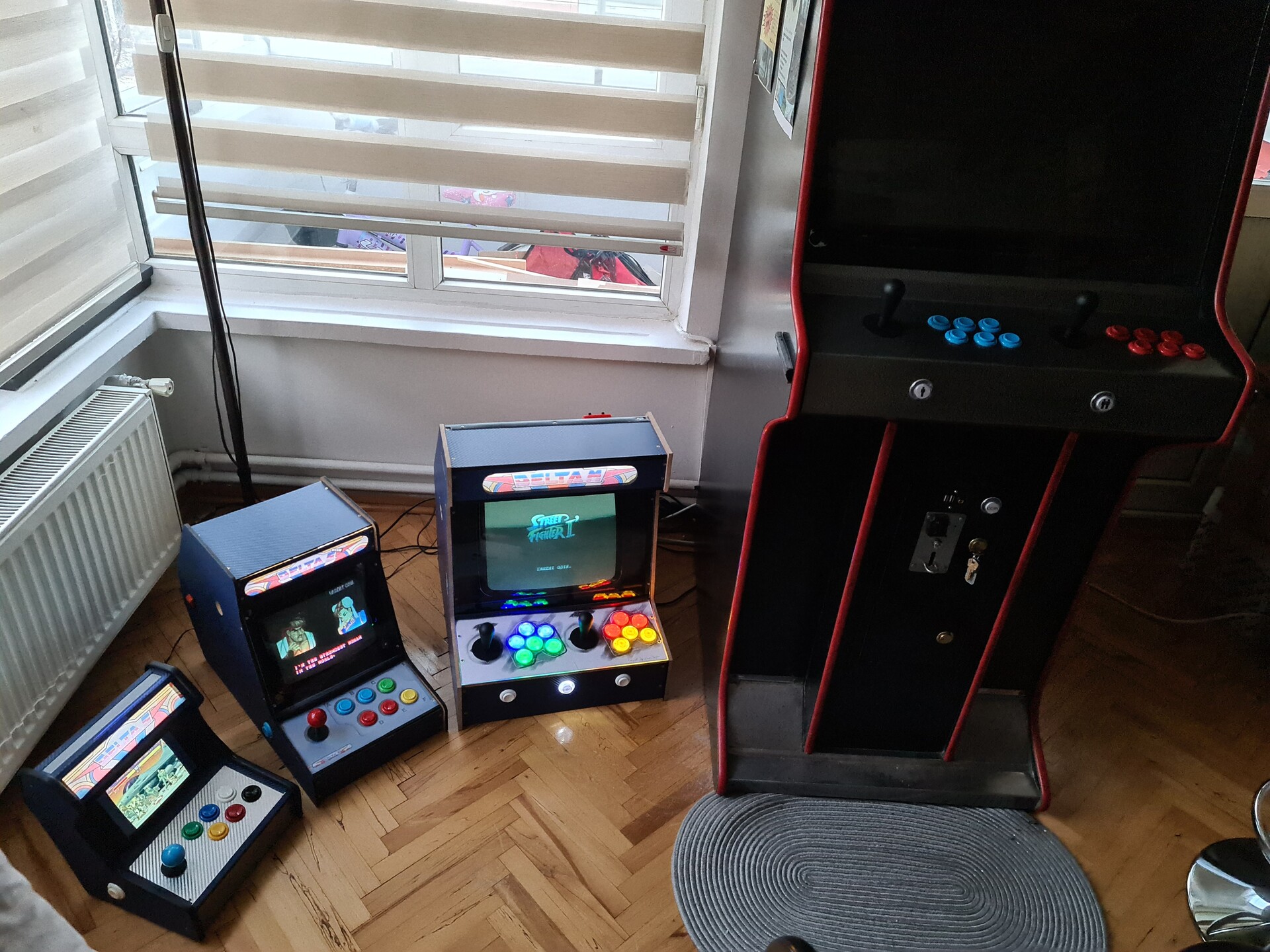
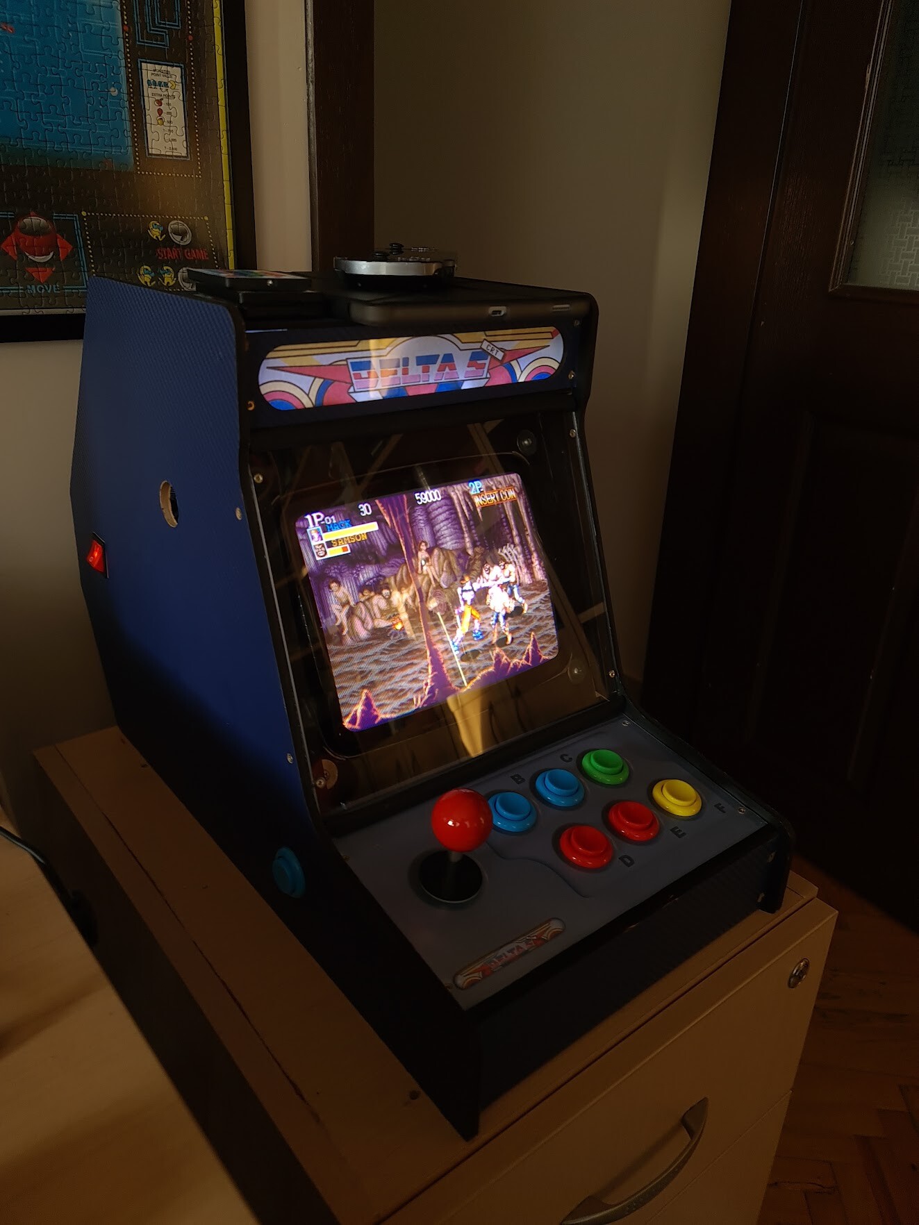
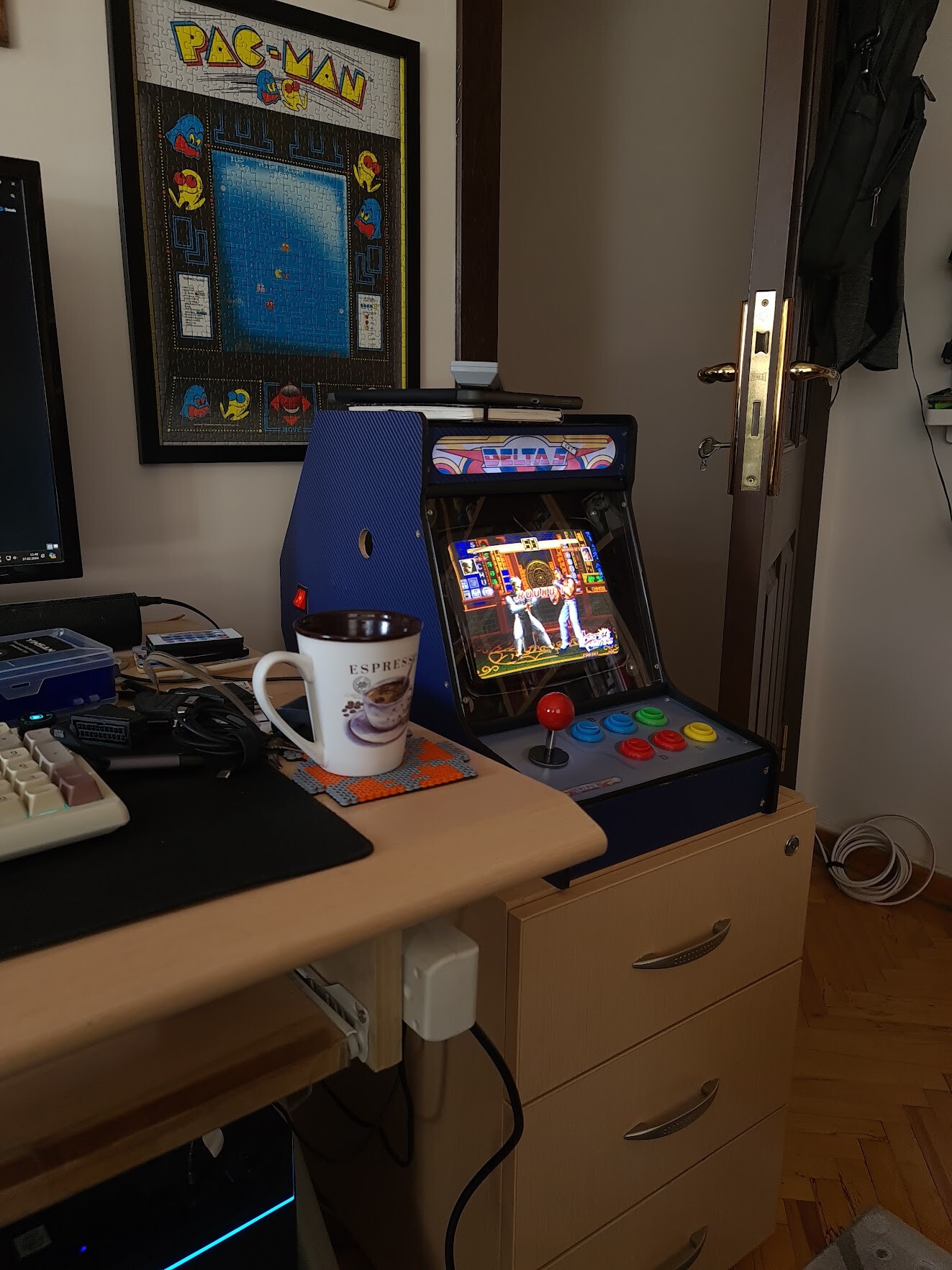
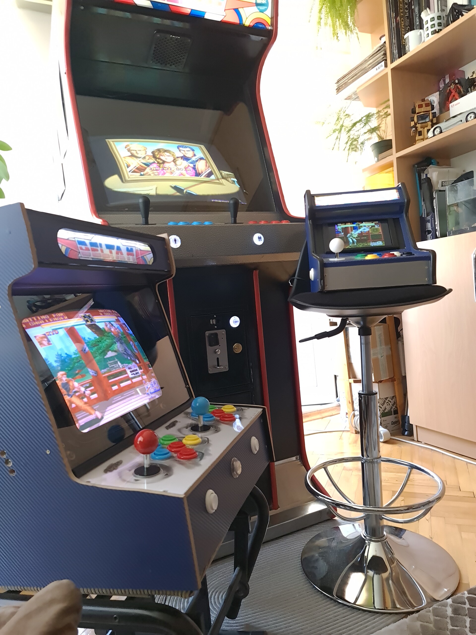
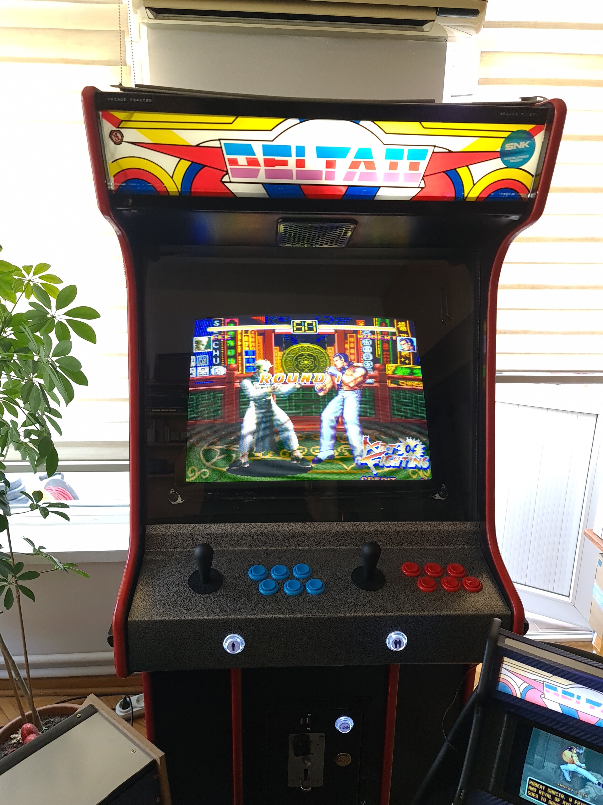
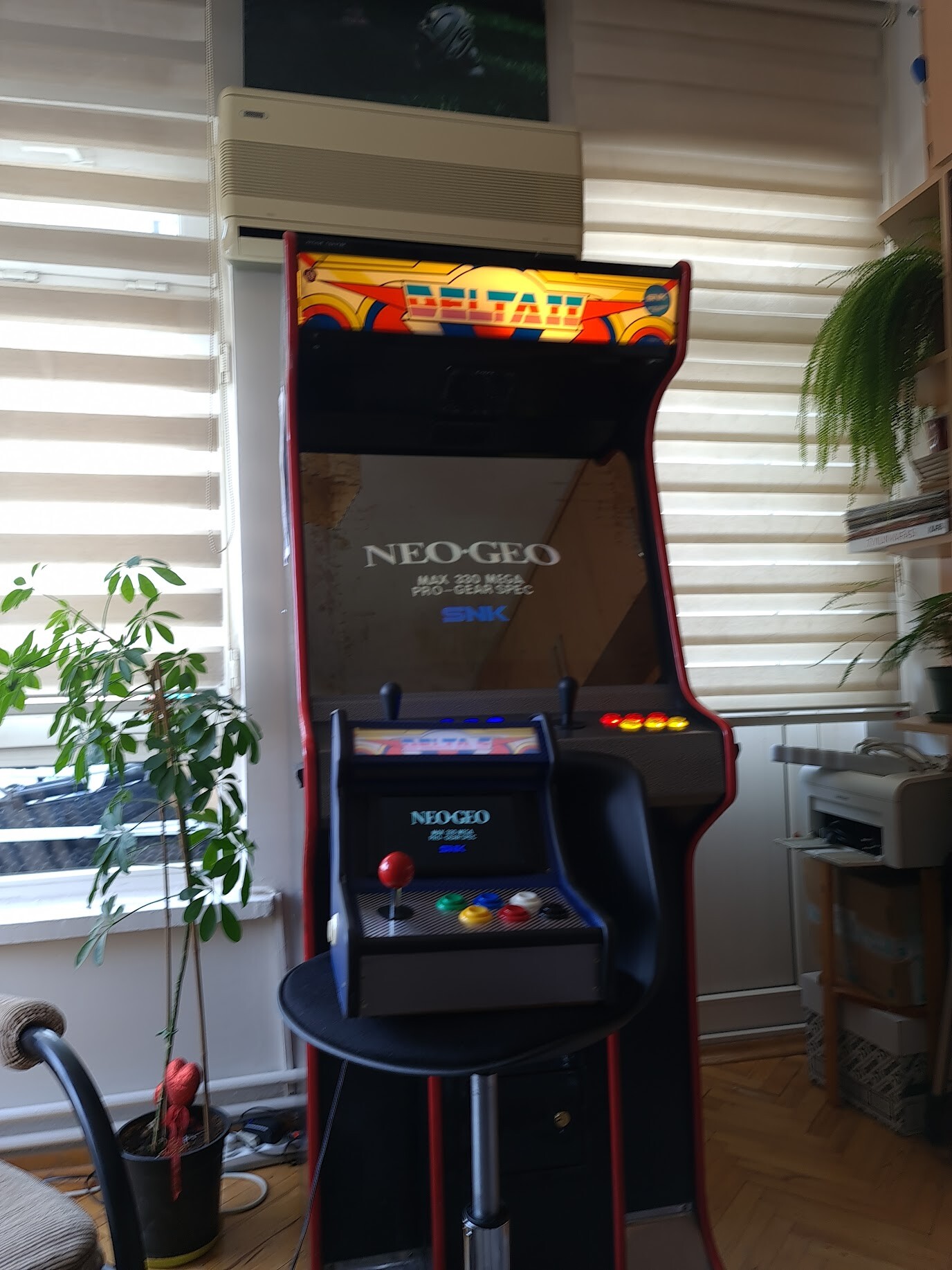
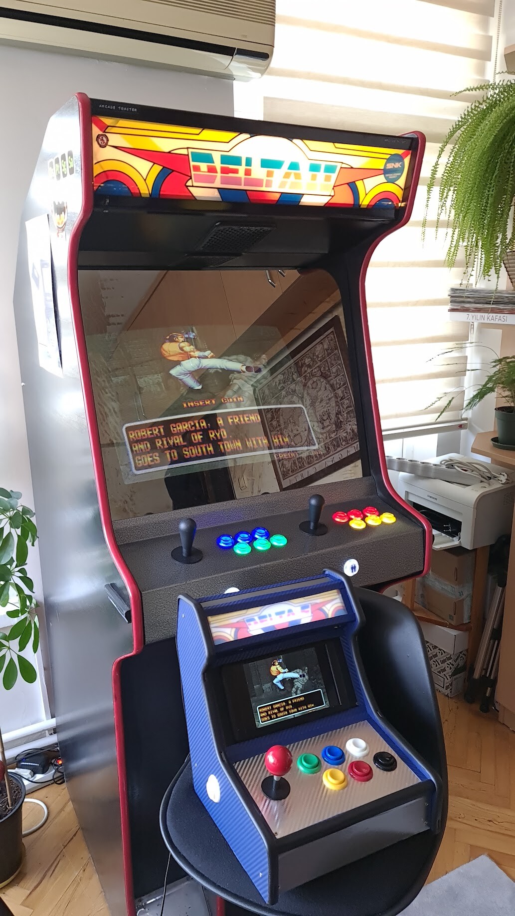
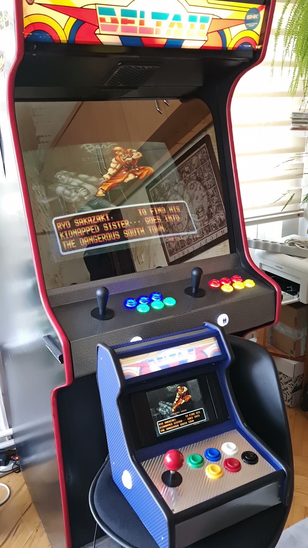
Some shots with the big cabinet and the new one.
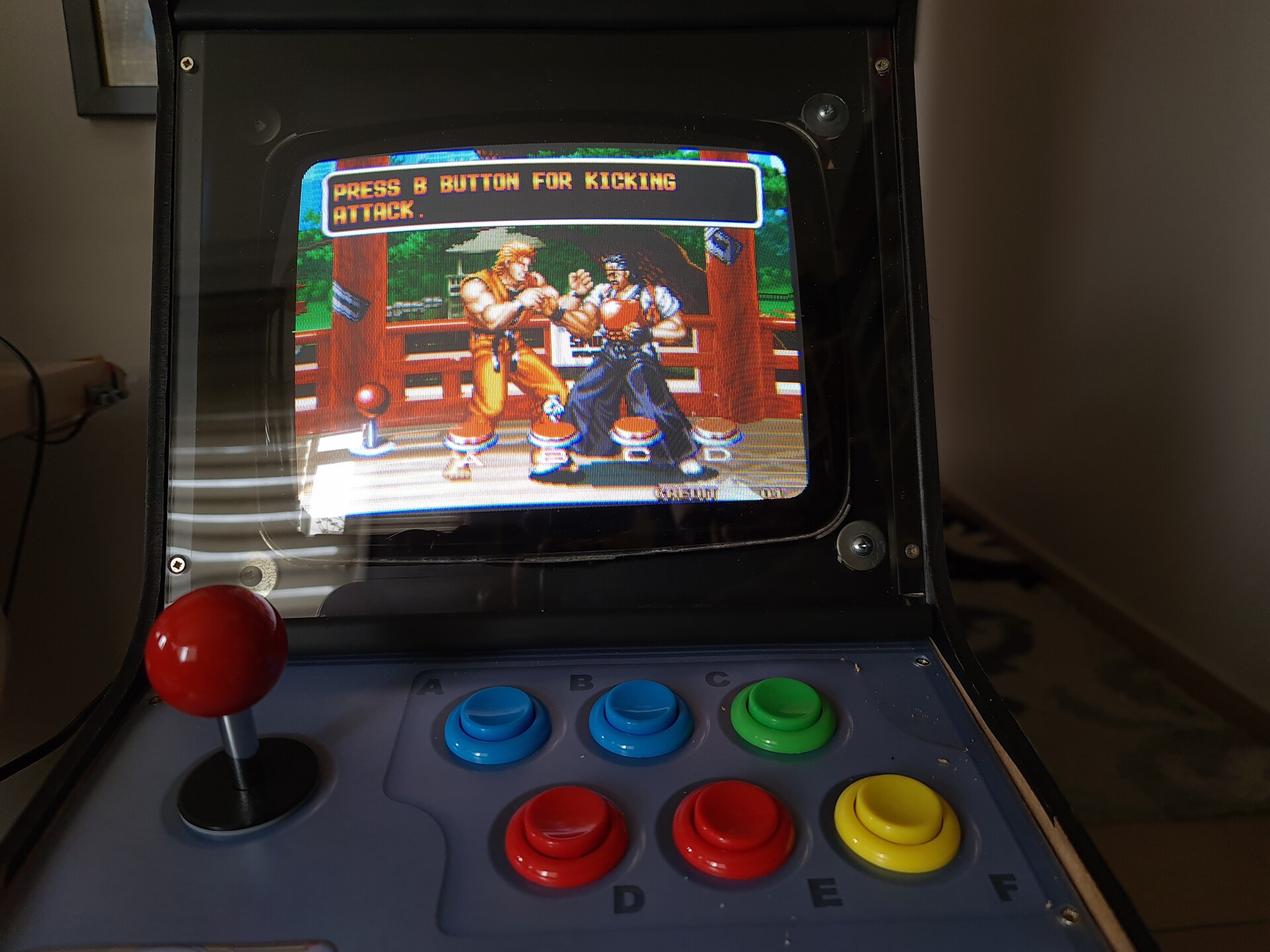
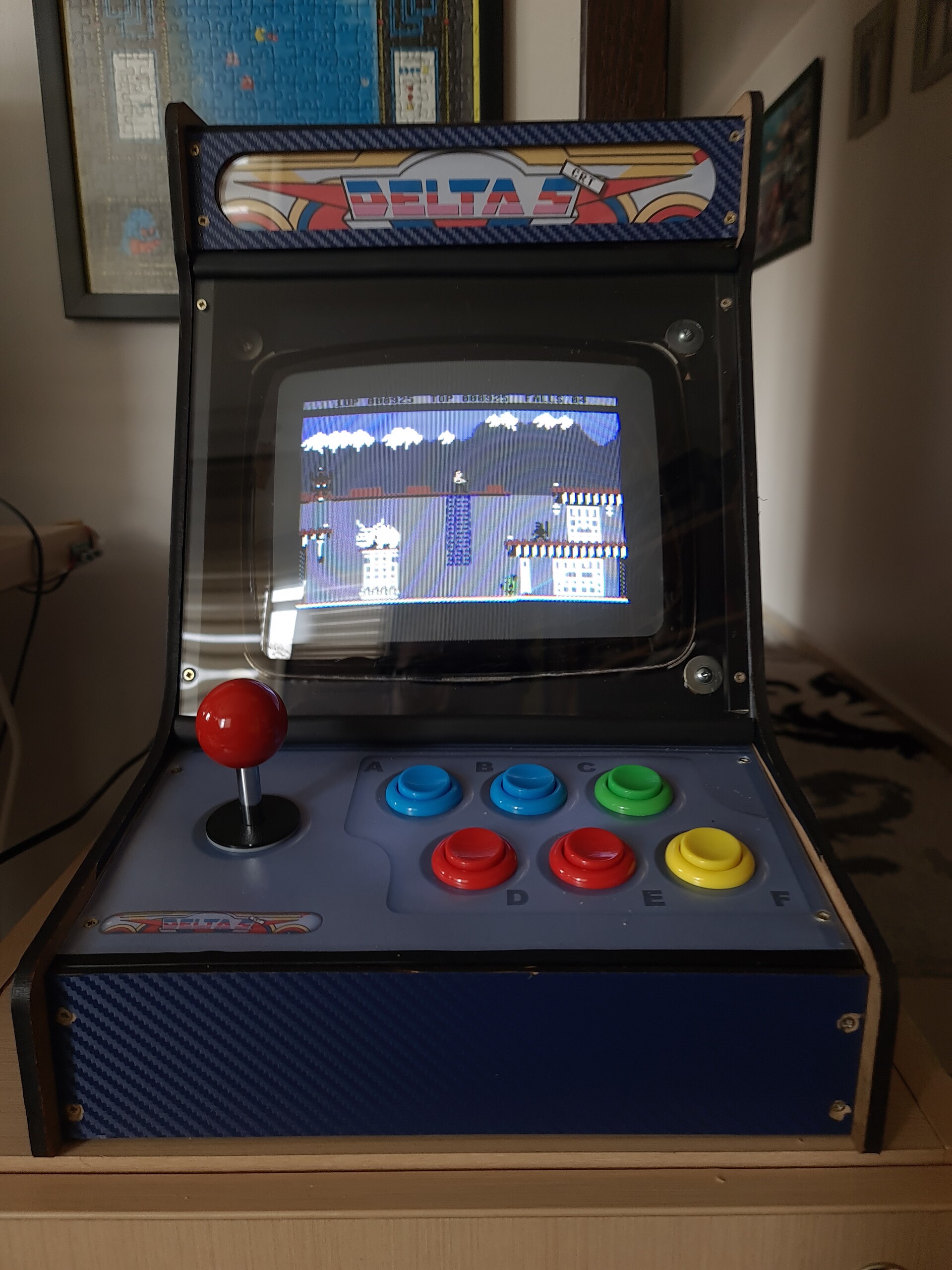
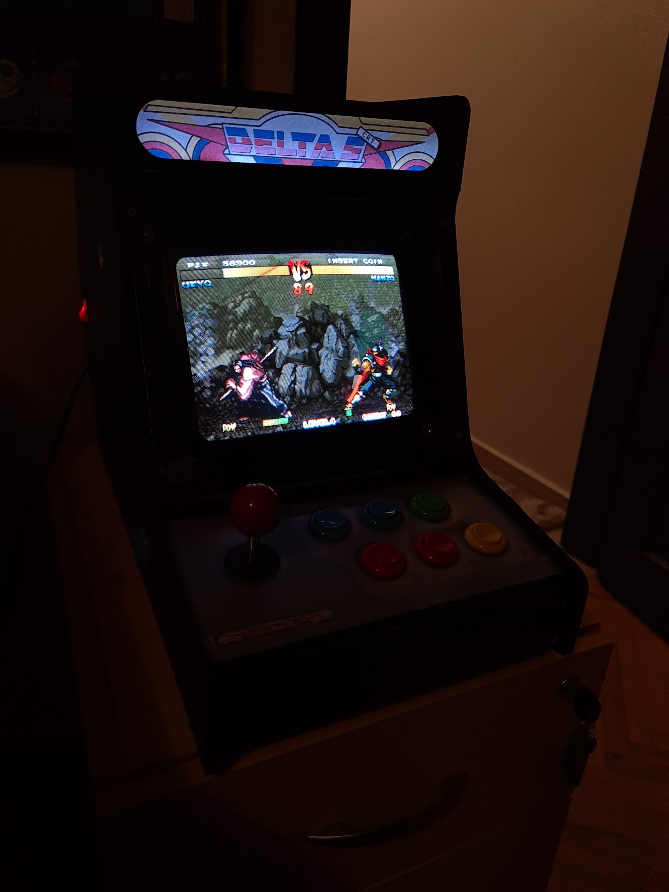
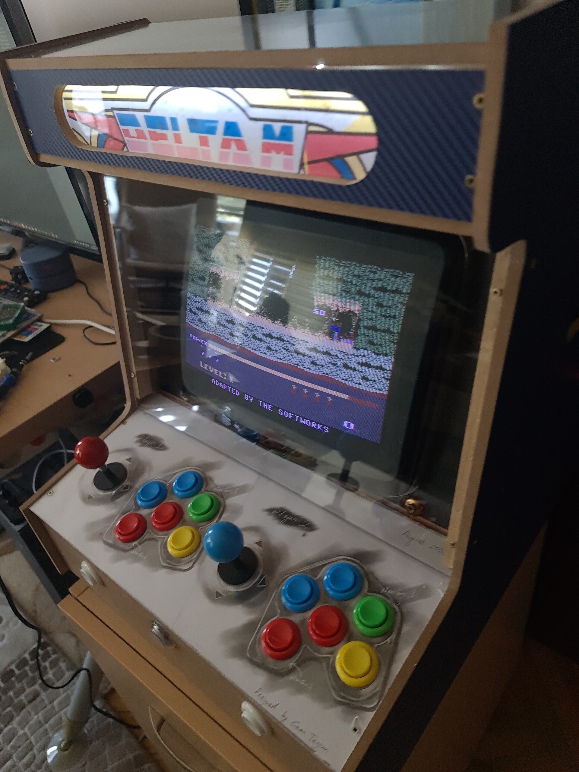
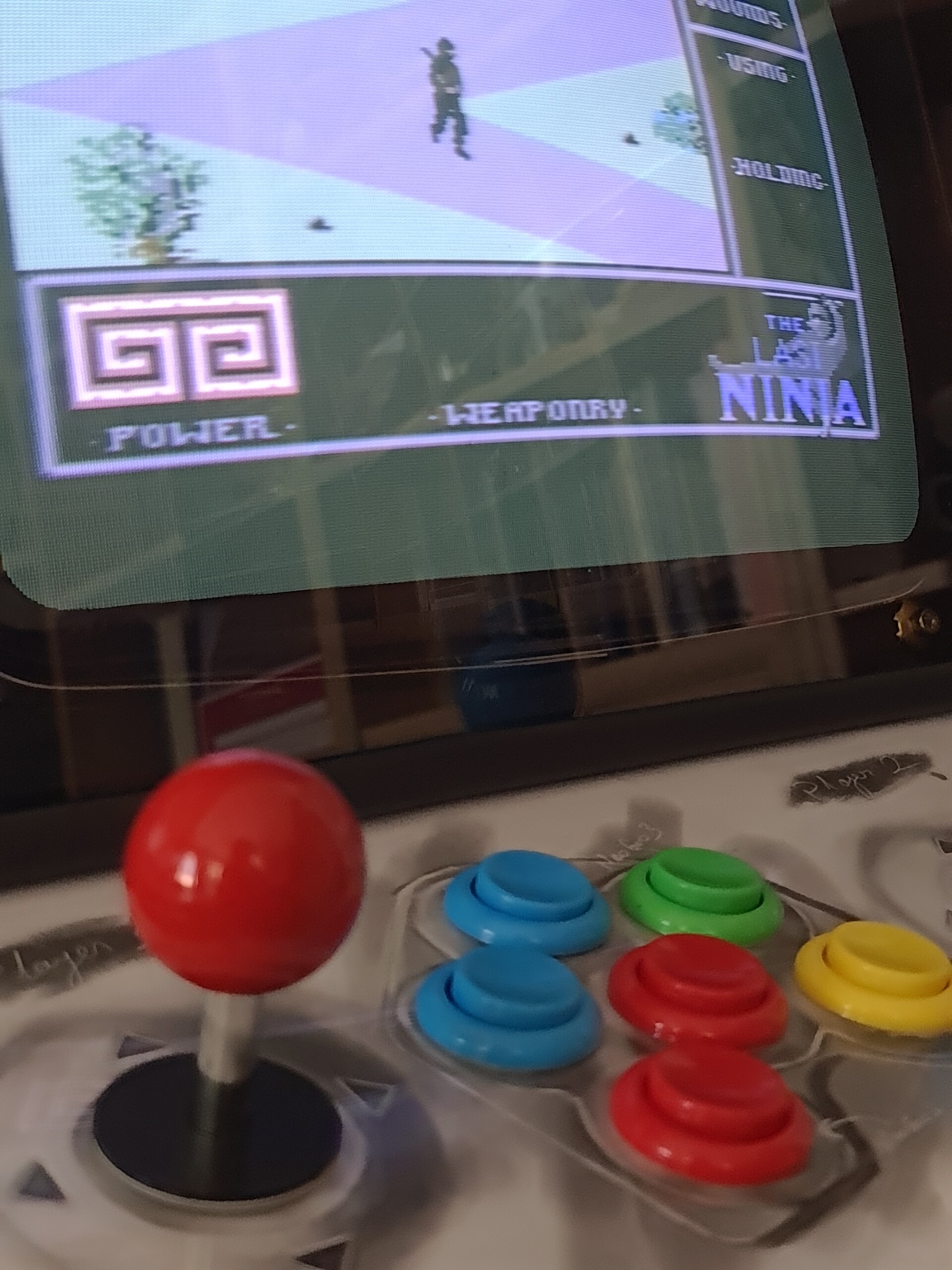
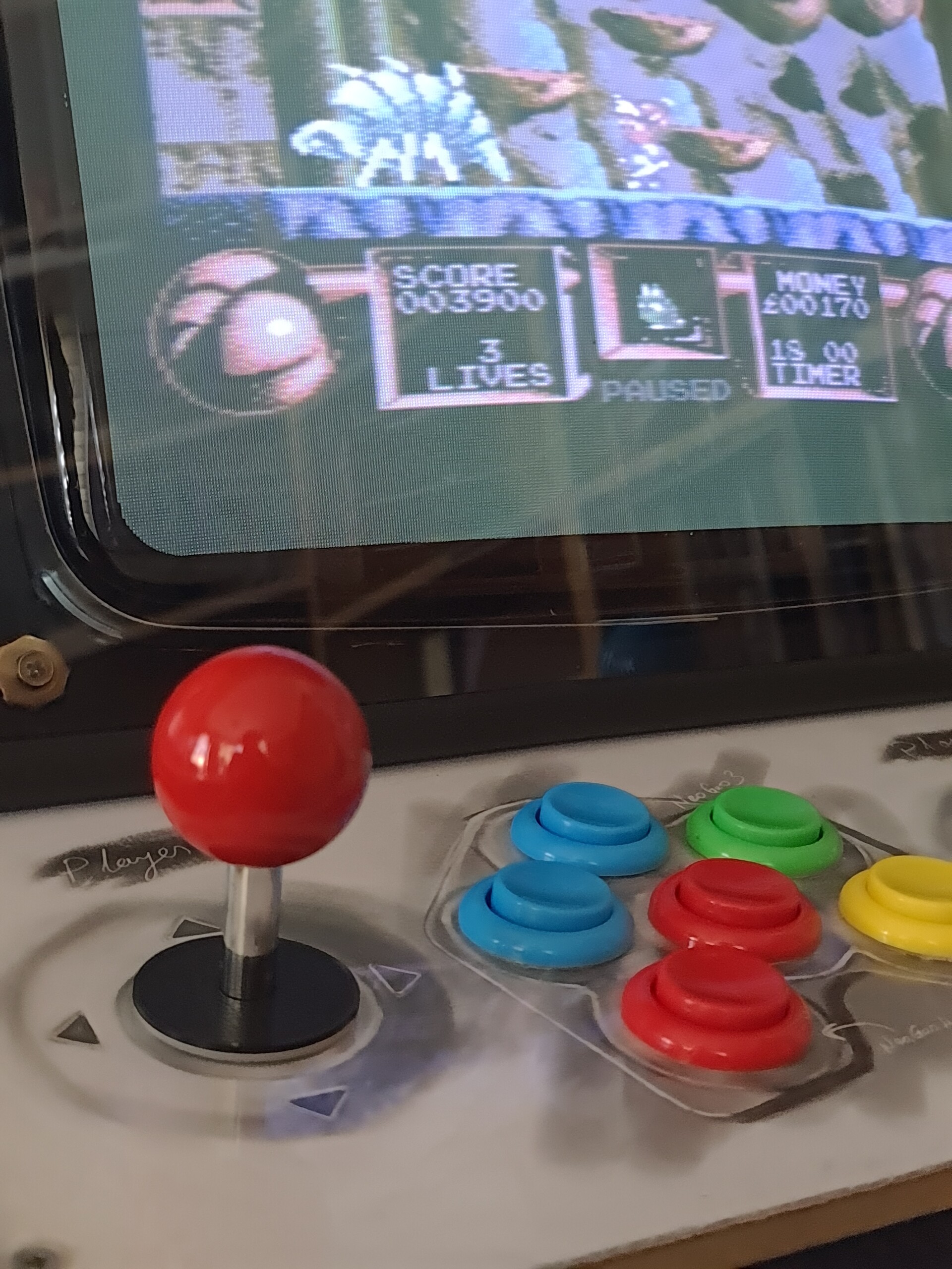
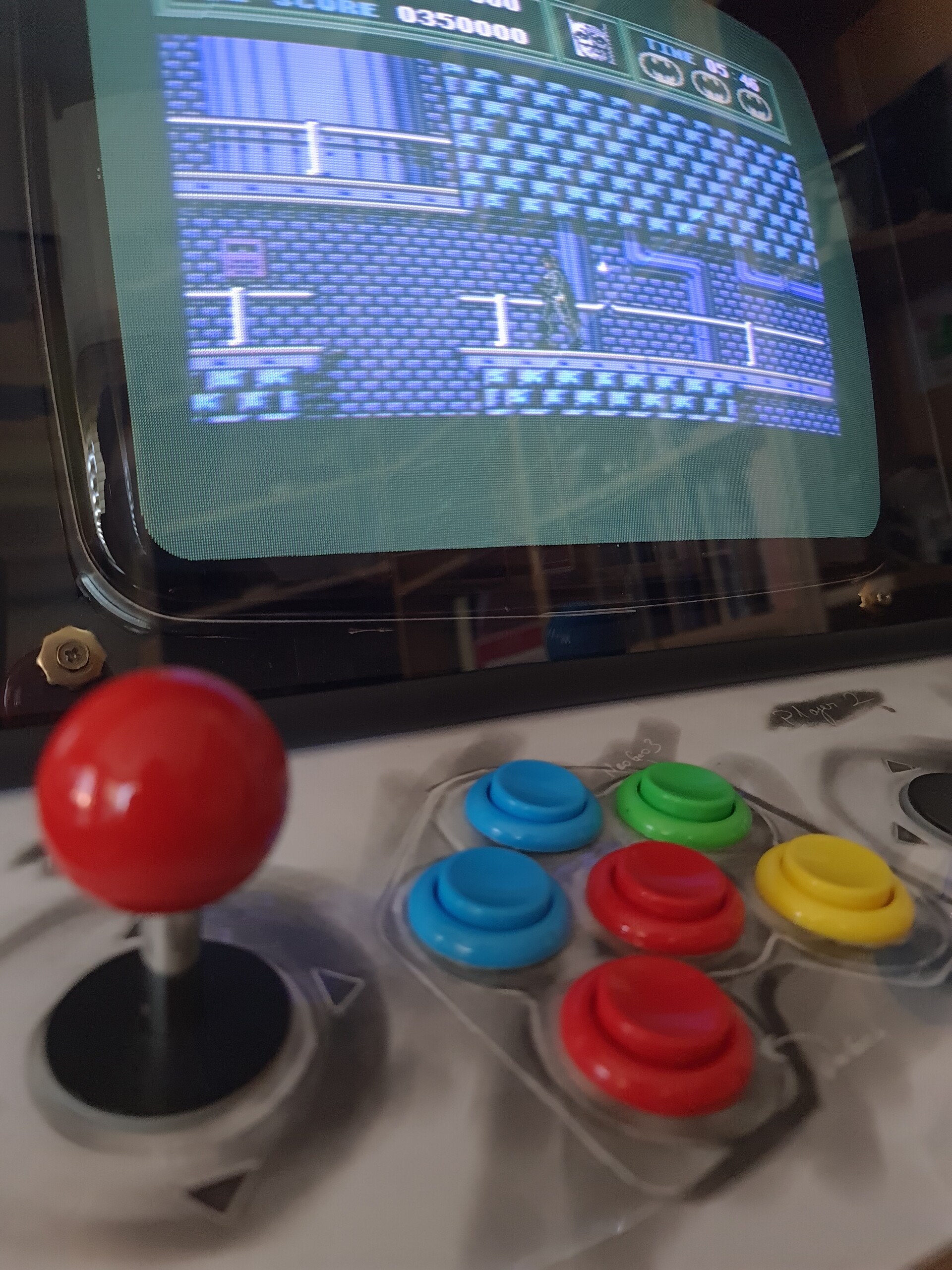
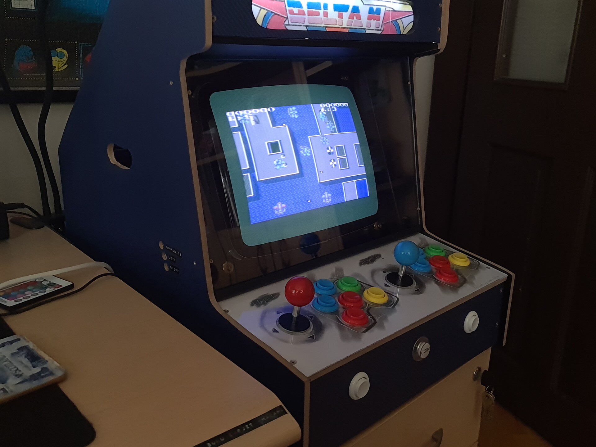
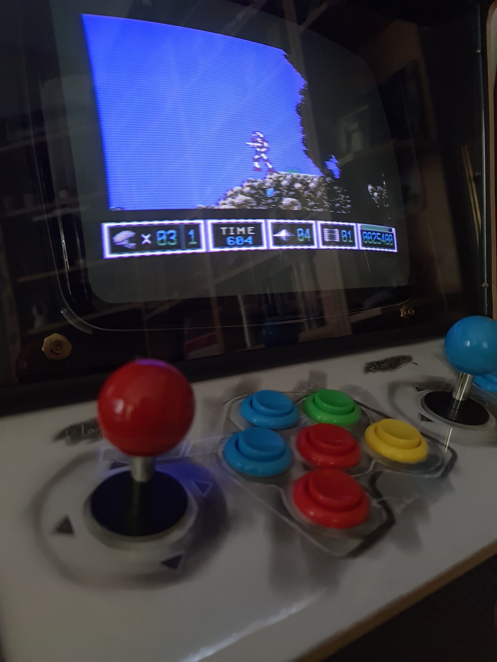
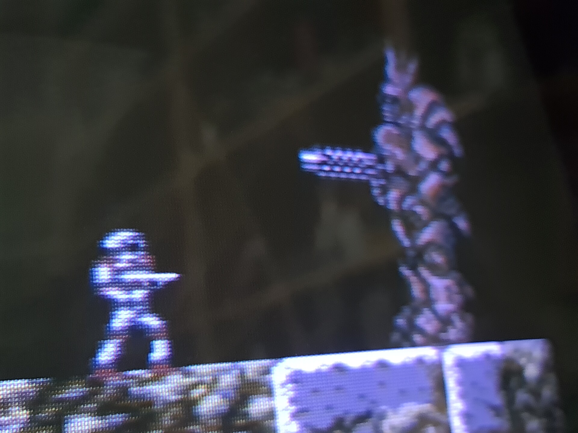
Let's test it out!


This is a brief timelapse of the project.


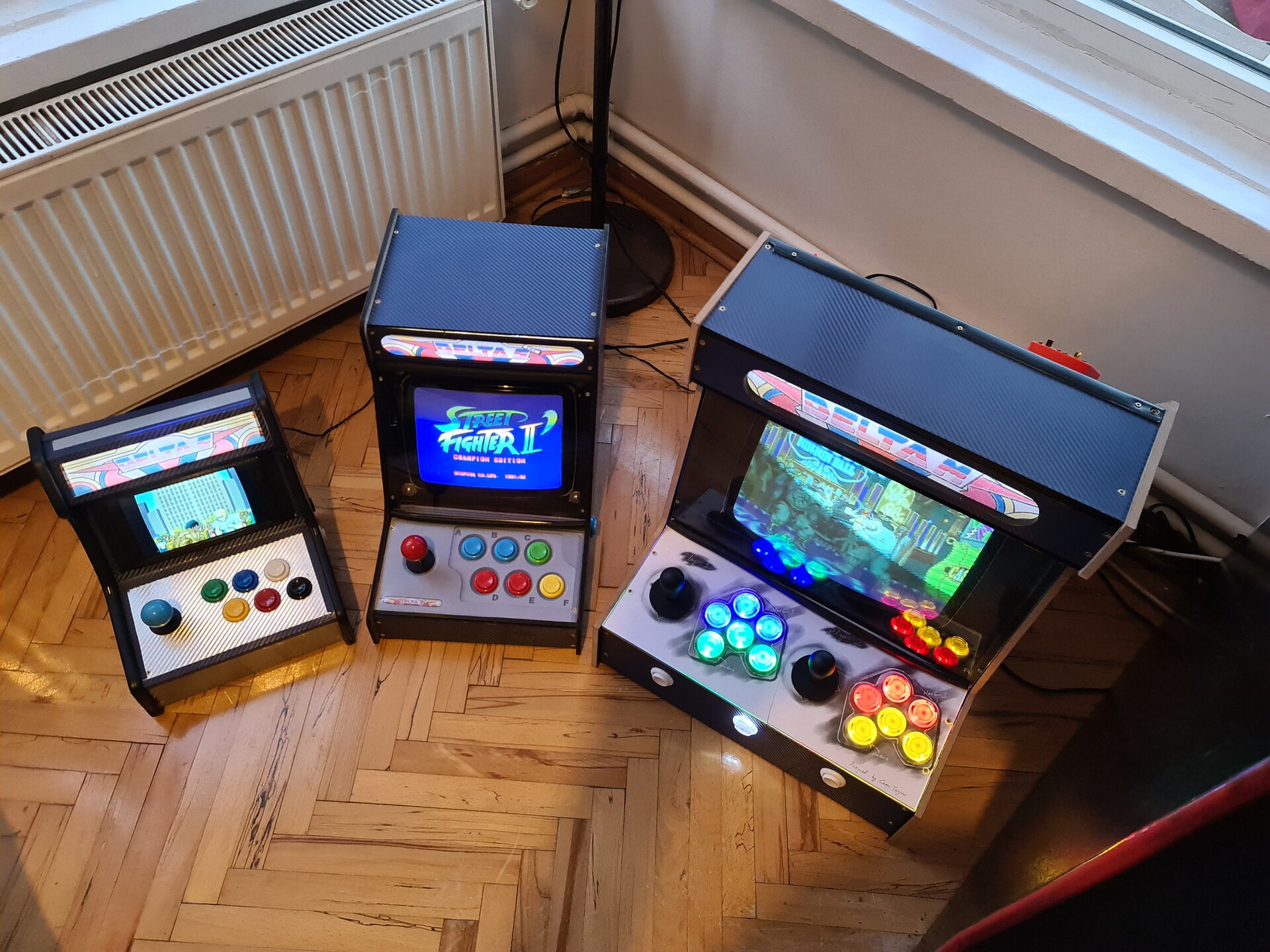
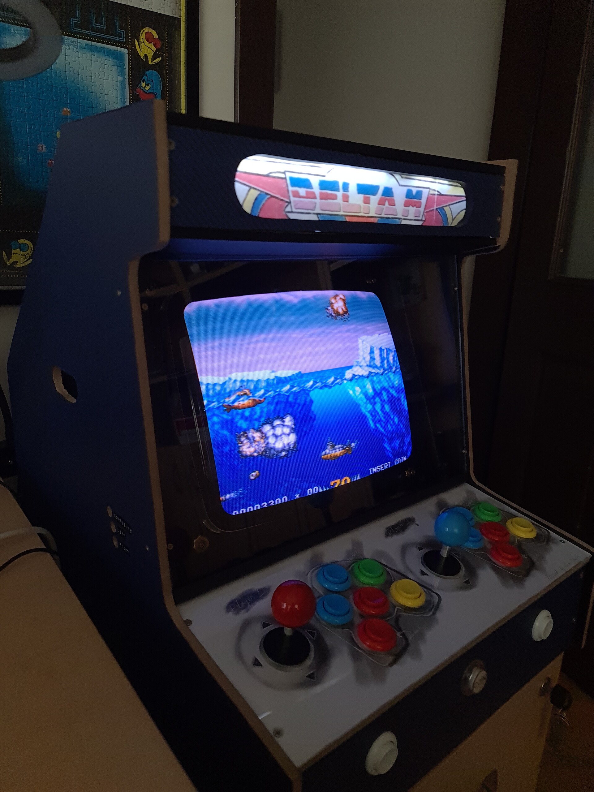
And one final shot with the clearglass light panel.

It was an amazing experience to create something like this. Normally I do 3d printing and electronic assembly to that cases with more lower form factors. But this one was a good practice to work with wood, larger form factor and a way of both mechanic and electronic device. I hope you like it too. And see you soon.


Botoy (1986) - A Lazy Robot Repair Story

Making Of / 28 August 2022

Hello everyone! I made an attempt to repair an old robot toy from my childhood. Actually this robot was owned by my little brother.

You may remember this robot from one of my artworks named "a Scene from 90s". When I was creating that scene about 3 years ago, I couldn't be able to get my hands to this toy, so I created the 3d model by finding photos of the toy from internet, instead of modeling it by correct measurements. I made enough similarity at least.

Anyway, toy is manifactured by Taiway (Shing Kee) Toys Co. Ltd. from China in 1986. It's called "Botoy".

First I checked up the product for the faulty parts. The most recognizable problem was the corroded battery compartment. That was the main reason that the robot is not operating.

I find some brass copper sheet to replace that connections. Also I removed the cables from the corroded parts and dumped all of them.

I tested the toy and it operated after that move.

Next I went for completing the missing parts of the robot.

Antenna part was easy. I modeled it with Solidworks by measuring the one at hand.

I 3d-printed the part with my Ender 3-v2 printer with black filament. We're good.

Nest step was the gun. The particular case with that gun is, it touches to the copper parts in the arm of the robot and got current to operate.

It was missing for a long time. So I checked the internet to get some photos of the gun to model and print it.

I had pretty much reference to 3d model the gun. For the inside part of it, I referred to my previous experience on creating cases for the electronics :)

For the red translucent part, I printed it with a white translucent part because I don't have red tinted translucent filament. Instead of it, I used red LED inside.

I used copper sheet once again for the connection areas to lit the gun. I thought form factor was challenging for a 3d printed case of that gun but I even had space left inside :)

Black screws would be better. Don't have any :(

Take cover!

For the last missing part, I checked the photos I gathered by google to model the keyboard part in front of the screen. this was the easiest part.

And as a one final replacement, I remodeled a rail part that connects head and the right arm to move accordingly. Because the existing part was breaking too much.

And the robot is completed as it was, back in 80s.

I'm sure there are some mechanical problems in the engine box, but I couldn't dare to open it yet, maybe next time. Meanwhile I will be looking for a solution for the ripped of transparent sticker on the screen. I hope you like this lazy replacement process, and have a good weekend :)

P.S. I can't believe I modeled this robot "that similar" by looking to the photos I gathered from the internet 3 years ago.


Adding a keyboard module to my Pixel Toaster

Making Of / 26 April 2022


Hello! Previously I made an handheld design using Raspberry PI and 3d Printing / Painting. This time I added a detachable keyboard module to my console so it would be easier to access whole c64 keyboard and experience.

You can check the making of process by this two links:
https://www.artstation.com/blogs/blockmind/lMOo/making-of-handheld-commodore-64-project
https://www.artstation.com/blogs/blockmind/lMee/handheld-commodore-64-project-finalization

This time with the help of C64Istanbul from PCBway, I got a keyboard replacement PCB where you can also order by this link:
https://www.pcbway.com/project/shareproject/COMMODORE_64_USB_KEYBOARD_FOR_BMC64_Poor_man_s_Keyrah_89d5c4fc.html

This keyboard has the exact mapping with a real C64 keyboard so the emulators recognize it %100 compatible. It uses an Arduino Pro Micro to make it reconized by a USB interface on the Raspberry PI or PC devices.

image courtasy C64iSTANBUL

So by having this keyboard PCB, I decided to make an expansion module for my handheld console. Normally I have a stand for the device to put it on surface vertically.

This two holes on my previous design made it possible to attach the keyboard module by here. So I completed the design according to that principle.

And 3d printed those with my good old Ender 3 v2.

After the printing I go for the weights. Since my design has a shifted weight center because of the angular screen case, I needed add extra weight in front of the keybaord unit. So I found some steel screws to use for that.

Since I'm using conductive materials as weight, to prevent any short circuit under the PCB, I isolated the back part with 3 layers of masking tape.

I also hacked the Promicro's usb input to use it as an extension cable. So I soldered 4 cables to relevent areas where you can see on this article.
https://www.instructables.com/Fixing-an-Arduino-Pro-Micro-the-USB-Port-Came-Off-/

This is the actual look of the bottom part of the case.

And the weights and keyboard works!


Before painting the parts, I masked the electronic components and the attachment hooks.

I used acyrillic paint with a special mixture to get the famous "Commodore Beige". Here is the recipe: %60 Mocca %40 Desert Brown :)

%100 color match with the old painting.

Let's do an assembly.

At that point, the thing that bothered my was the white color of the faceplate. they can be ordered in few colors but any of them cannot match with the beige color. So I decided to change the color of it. Overpainting it with a thinner was not an option. because the surface was too glossy to hold the paint. 

I found a strange workaround about this. I decided to print the same design with beige background with my color printer. But I printed the design on a sticker paper.

Next I needed to use my laminator device to cover the paper with PVC. Because standad paper would worn out in time while using the keyboard.

Laminators work with heat treatment to make the PVC sheet welded with the paper. Perfect way of protection. To make it one sided to my printed sticker, I added an extra layer of standard paper to the backside of the sticker.

This way I had my sticker PVC laminated on the printed side where I can also easily peel off the cover for the sticky side.

My next problem with this printed keyboard layout was the holes. These holes are drilled by machines, so making holes by hand was not an easy task. I also printed the outline of the holes and to make the holed I modified a pen as a punch pen :)

I used various drill bits to enlarge and sharpen the tip of the pen.

So I used this punch pen to punch the holes.

And finally I applied the sticker on top of the faceplate. Very acceptable match!

It looks way better than the white one because of the color match.

I didn't stop there. My next step was to add some SMD LED lights to the clearance I designed for the screw heads. It lookedlike a perfect placeto add the lights for some decorative key lighting.

I soldered a simple board for the resistors of the LEDs. I added a 90 degree pins to put a connector, because board is on the bottom part, and the LEDs are on the top part. So I needed to detach LEDs from the bottom part of the case for maintenance purposes.

And the lights on!

These are not so powerful lights bu they added a nice touch I suppose.

For the USB connector, I made up a case like this. I know it's not looking so good but at least it secured the soldier and cables on the tip.

Because of the bad masking decision I made, the bottom keyboard module was looking like this:

I kept that black are masked because it is the attachment hooks. Painting them will cause losing tolerances on the shrink fit. But it looks terrible this way and even it's not exposed after attaching to the screen, I wouldn't let it be like that. So I re-painted that area. But as you can see, there was an height level variation between the first paint and the secondary paint surfaces.

I sand papered it and painted one last time and it's done!

And finally completed this project. Here is the final shots about it. 

It was a real fun making this device get closer to my reverse-visionary HX-64 design (https://www.artstation.com/artwork/dOqA8K) and it was great to make up some homebrew workarounds during the process. I hope you like it too!


And some FPV shots :)

Cheers!

Handheld Commodore 64 Project - Finalization

Making Of / 24 June 2021

Hello once again,

Previously I made a case design for a handheld Commodore 64 that I made by a Raspberry Pi. You can see the making of process by this blog post.

https://www.artstation.com/blockmind/blog/lMOo/making-of-handheld-commodore-64-project

I know that project has been a disaster on 3d printing, so the resulted case was not looking good enough. 

This posts shows what I did to save the look of the device :)

As a started I re-printed the top part.

Next I used putty over the case parts.

And sanded after it dried.

I painted the parts with a primer.

...and made some tiny scratching on cavities.


Now it's time for painting with reference color!


Not close enough, but still it can be used for the first coat of painting. 


Second trial had been better on match.


And this is the resulted piece!

Acceptable color match!


And leaving some more shots here:


I hope you like it this post process. Cheers!

Making of Handheld Commodore 64 Project

Making Of / 20 June 2021

Hello, I'm here with another homebrew Commodore 64 Handheld project! It is a Raspberry Pi-emulated electronic assembly. It has it's own screen, it has two 18650 batteries inside that makes it work for 3 hours and 55 minutes in full load with gamepad activity.

You can see more info about this device in this video:


I used BMC 64 emulator on this device. You can find it by this link: www.accentual.com/bmc64


Here is the simple diagram of the components

First I combined these parts on my table and measured them. I modeled rough blocks of these in Solidworks and made a placement first.

Next by considering the port clearences and placement, I modeled a 3d printable case.

After modeling is done, I 3d printed the bottom part first and fixed the components on it.

For the controller part, I made a different approach on this one. I directly used a controller circuit which I detached from a very cheap gamepad controller (around $4). Because all GPIO pins on the Raspberrry Pi is used on IPS screen. So I needed to connect the controller with a USB interface. Instead of doing it with an Arduino, I directly used a gamepad circuit which was faster way :)


And fixed the screen to top part as well.


And we have the whole system cased!


And system works! (I know I work messy - P.S. no apricot seeds are used on this project)


The top part was 3d printed very bad because of some filament issues and placement. I tried to recover the bad surface by a 3d print surface finisher tool that makes ironing.


I know, it's not perfect but at least it can be sanded and painted later...


Tape loading!

The last ninja!

♥️

Dimensional reference photo (metric)

Some nature photos! In my childhood, some travels we do was sperating me with my Commodore 64. I wish it was possible for me to build this device in 1989 :)


And some renders! You can find the rendering project page by this link: https://www.artstation.com/artwork/GalrWW


I hope you like it! And thanks for your attention as always!

Portable BMC 64 Emulator - Mk II (Painting)

Making Of / 30 March 2021

Last weekend I painted this case by trying to match the colors of breadbin cases. 

Actually, it was very hard to match the color by mixing acyrillic paints that I have. 

Anyway, first I applied a surface primer (gray) and then used sandpapering to clean up surfaces. After that I used putty to fill layered surfaces that caused by 3d printing. And applied sandpapering again. 

Careful while using this kind of putty products (in my case Tamiya Putty). There are huge warnings about how hazardous they are.

I'm trying to match a color here but it's far from good. So I decided to use it as a one more primer layer to sandpaper once again. 

Sandpapering again has made the gray at the bottom look more visible like some Substance Painter edge damage filter is applied :)


Color in the container is my second mix where you can see that previous one (the right part) looking more off.

I'm using airbrush for the job BTW.

And looks better.


Finally I assembled the pieces and paint the icons on the front panel with black permanent pen.

A close up with flashlight.  

One comparison with Commodore 1702 monitor.

Now it looks more like the one I rendered for the the blister pack project on my portfolio :)

https://www.artstation.com/artwork/lxbNeo 


And oıne final comparison with before and after the painting process.