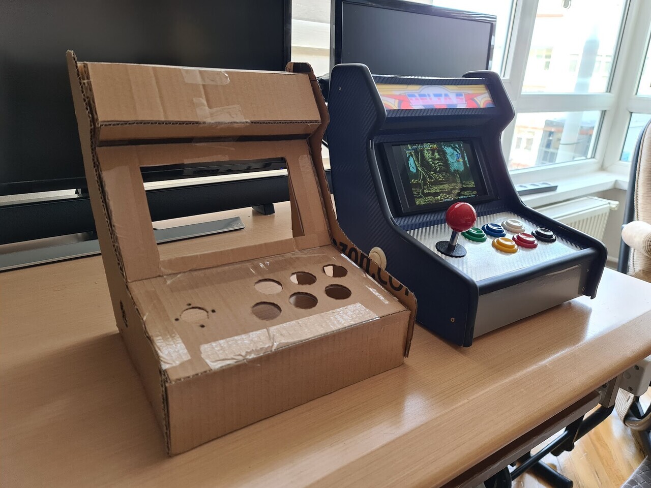
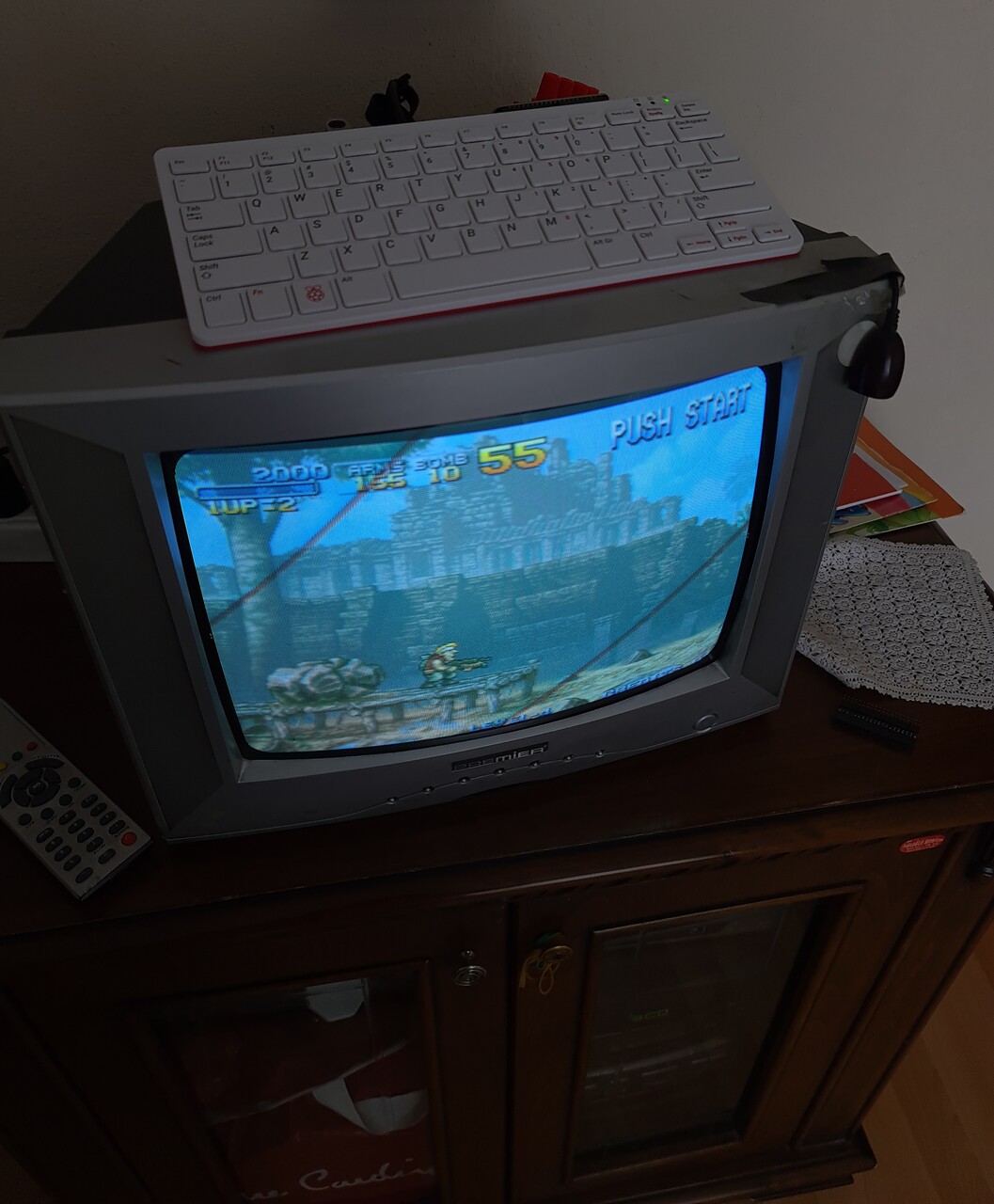
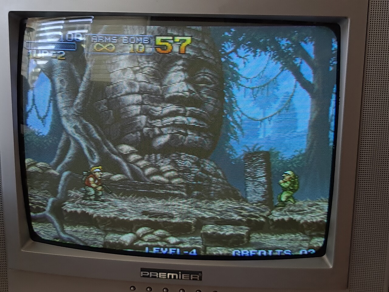
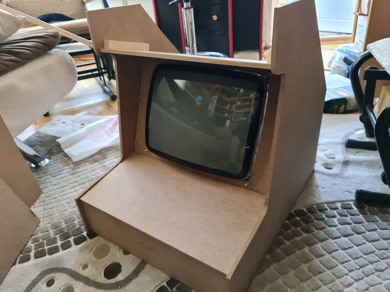
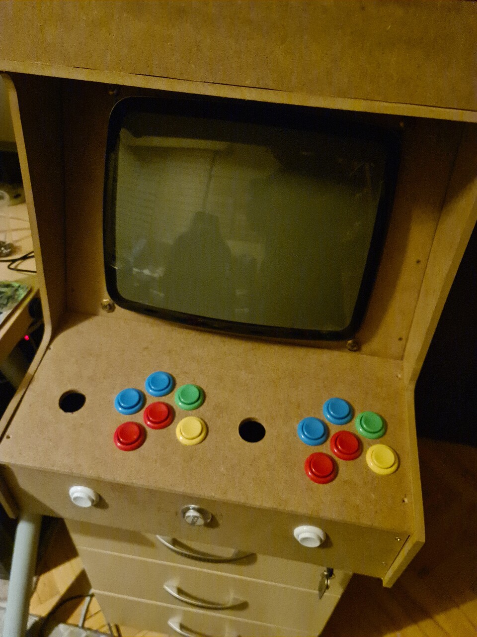
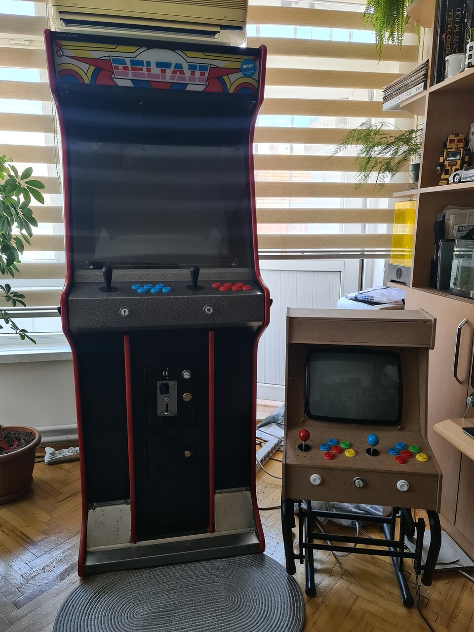
Hello everyone, recently I made another Bartop style arcade cabinet with a CRT screen. This was a real fun project, but the best part is I made it in home by the tools I have. So you can consider it's most part by "DIY".
Bartop Arcade Cabinets are roughly more like a trimmed version of upright (classical) cabinets. But they are also designed with smaller screens so the size is smaller as well. You can put them on a table to play. I made an LCD version with one player controller previously. You can check that previous project by this link:
https://www.artstation.com/blogs/blockmind/PvdE/making-of-a-tabletop-arcade-machine
1. Starting Point of Designing the Cabinet
1.1. The Screen
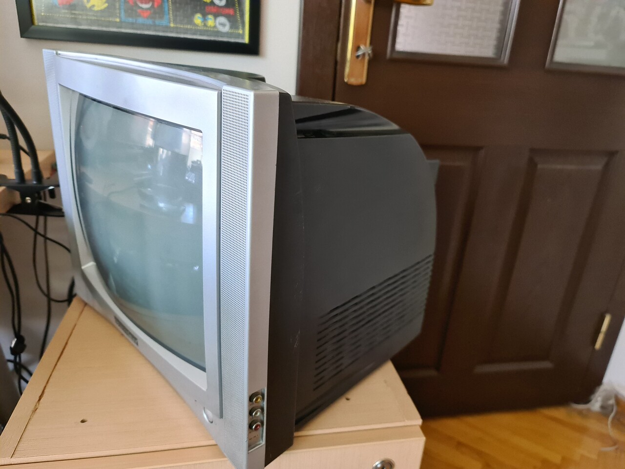
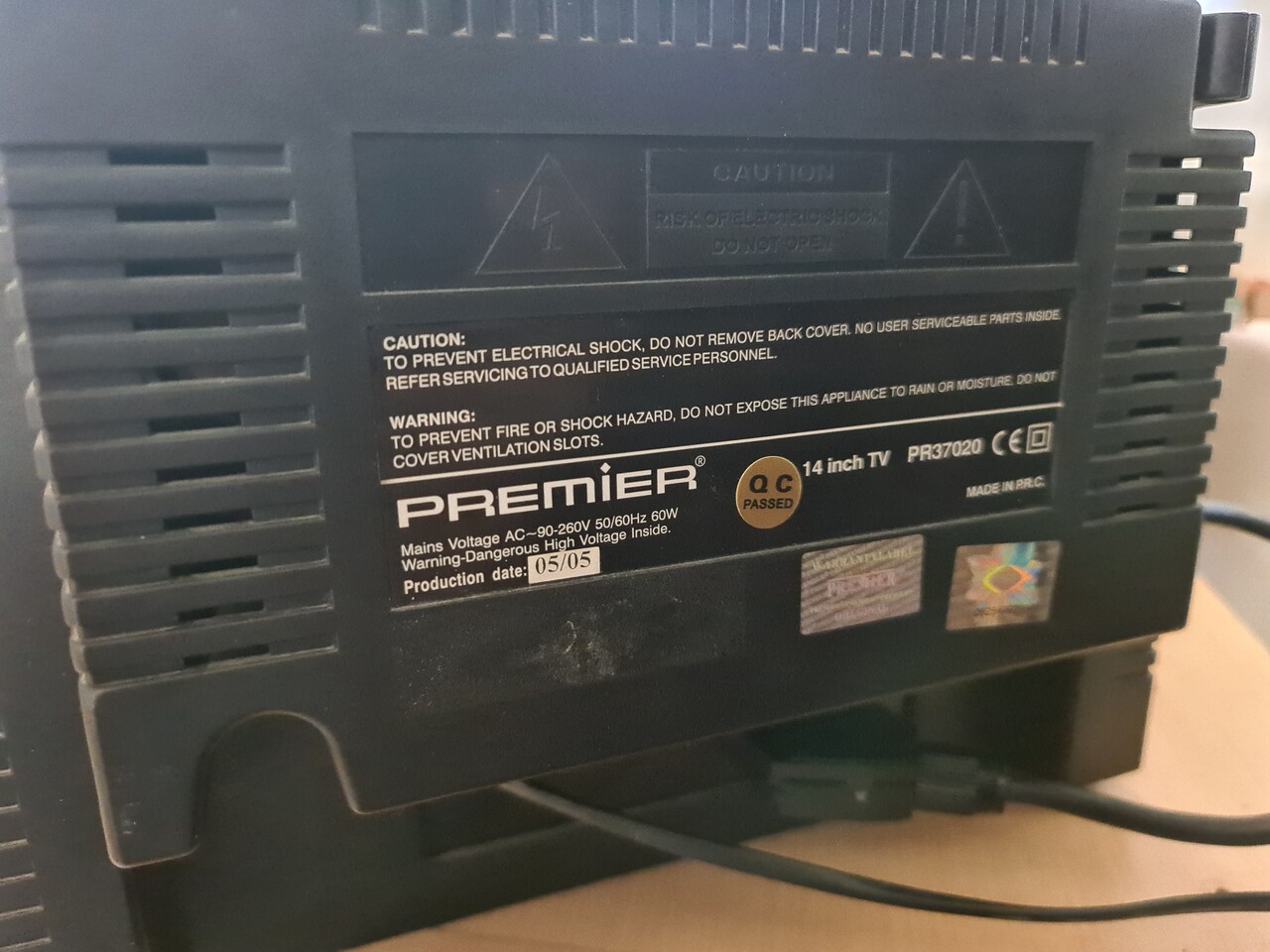
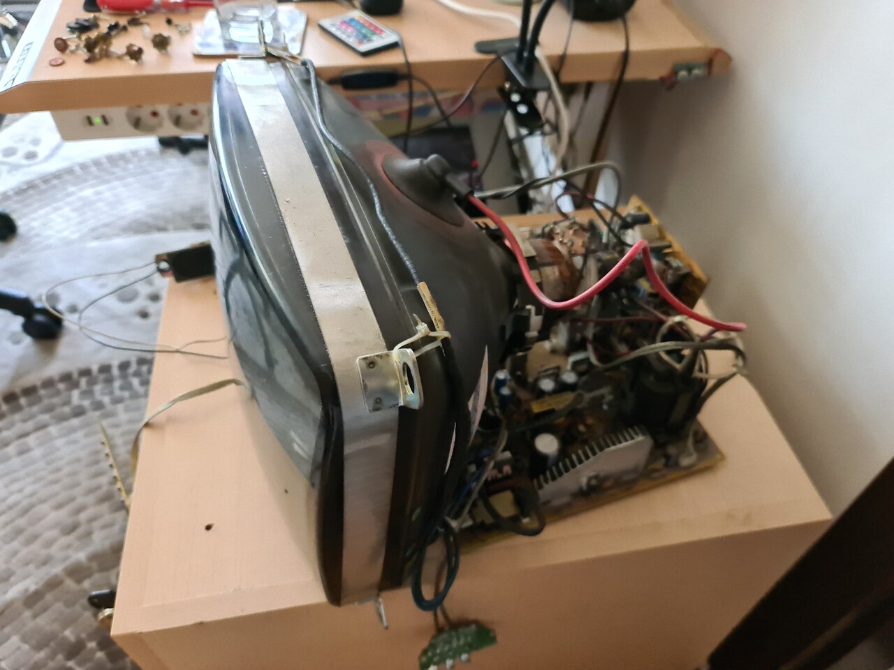
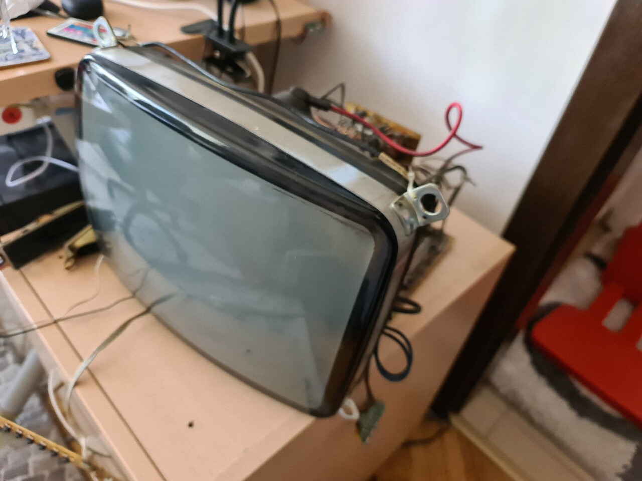
The main purpose of this cabinet was the "Premier" branded CRT TV that I saw in the house of my mother-in-law. It was a 14" CRT TV that show the pixels in a very good way. Also that TV supports refresh rates from 50hz to 60hz. And one the best thing about that TV was that it aligns screensize automatically, I don't know how.
That TV made me think of creating another bartop cabinet by using that kind of CRT screen since it's small, but had enough size to show the pixels and games.
1.2. The Emulator and The Hardware
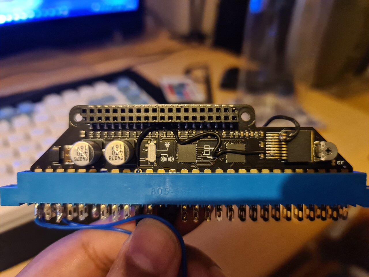
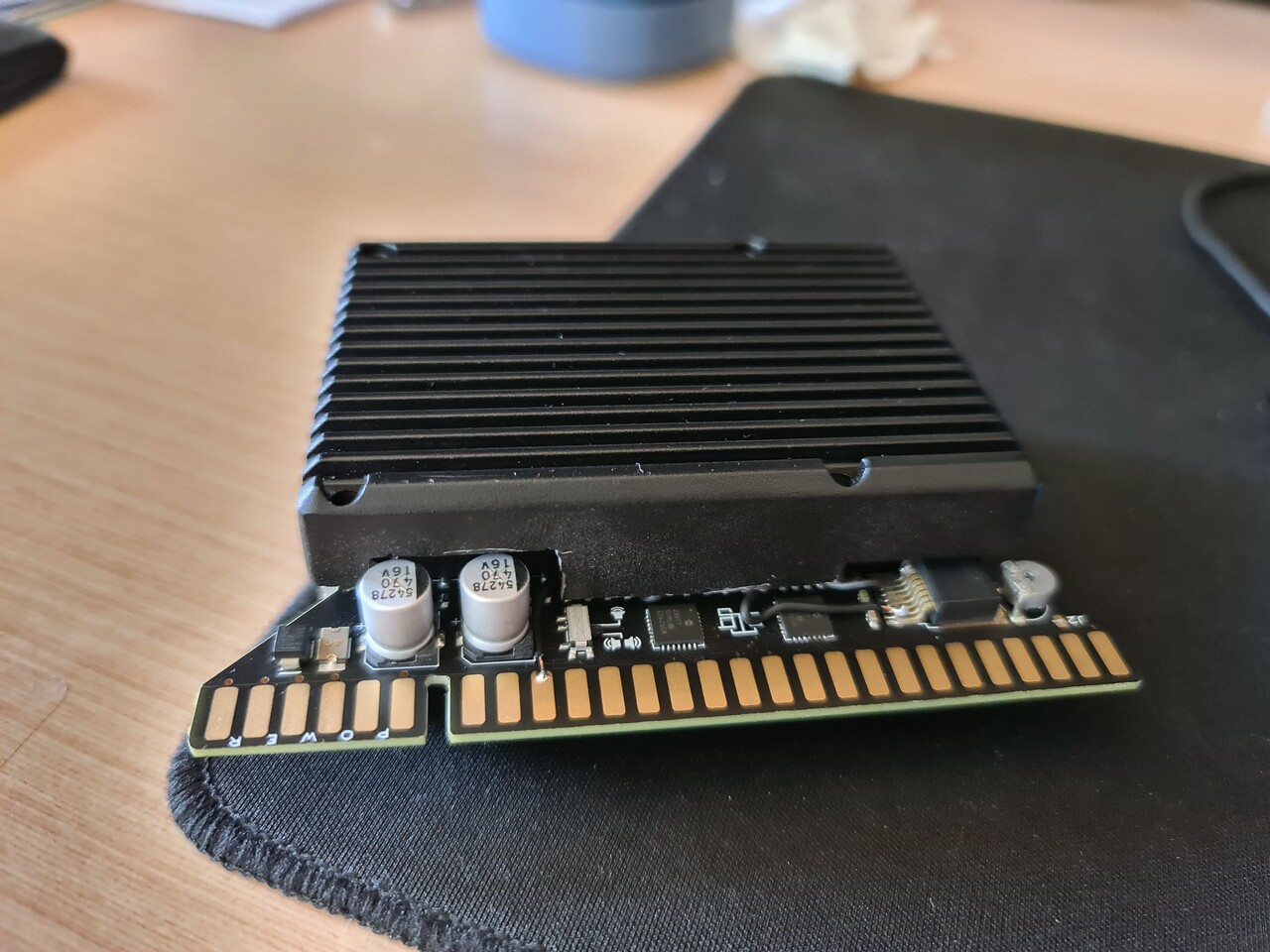
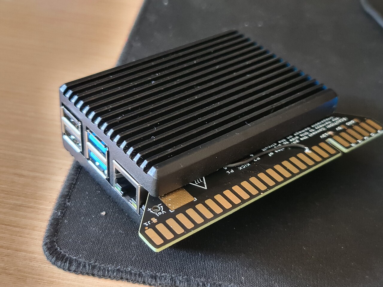
Another component that I had was an "RGB-Pi jamma hat" that can be used on Raspberry Pi devices to emulate arcade games. You can purchase different types of RGB-Pi products by this link: https://www.rgb-pi.com/
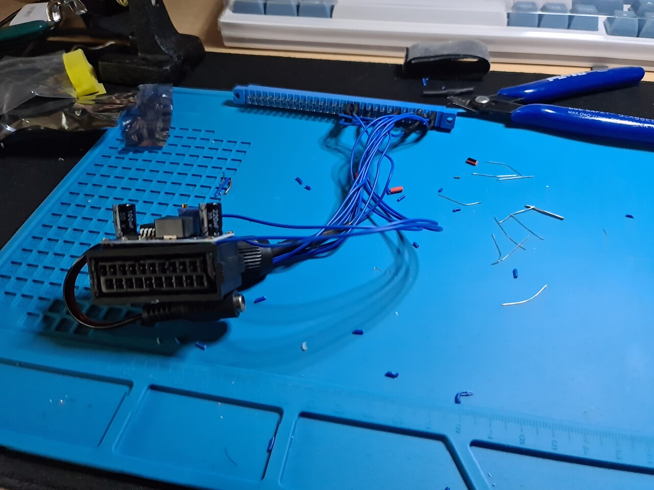
Normally if I had a RGB-Pi Scart instead of RGB-Pi Jamma I could connect it directly to these TVs but since my connection type is JAMMA then I needed to convert the jamma signal pinout to scart pinout.
The best thing about these devices, they have a special software that compatible only with this hardware that runs the games in various refresh rates fixed to the original rate of the arcade game that you play. This part is the real tricky and one of the most important part on arcade game emulation. Because with modern equipments, we're playing those in a wrong speed. Every arcade game back in time had a specific refresh rate. Here are some examples:
- Street Fighter II - 59.637405 Hz
- Shadow Dancer - 57.230000 Hz
- Mortal Kombat 1-2-3 - 54.706840 Hz
Consider these values as FPS of those games. But once you play those games in a PC, PSP, PS Vita or Retropie etc. you have a fixed 60 fps refresh rate. Thich means for the sake of smooth scrolling, emulator shows more frames than the actual framerate of the game. you play Mortal Kombat 9.6 percent faster than you used to be in 90s. Shocking, eh? Check this video.
Original refresh rate can only be achieved on a proper CRT screen with a proper sync signal which is generated by a proper raspberry pi device with a proper emulator. So my electronics setup is formed.
2. JAMMA to SCART Conversion
Only problem was that my RGB-Pi hardware was JAMMA version. So I needed to make a convertion from Jamma to Scart. Because SCART is the easiest and the best connection for the TVs which is analog RGB.
I followed this two diagram and applied it between a jamma connector and a female scart connector.
Source: https://www.mortaca.com/rgb-pi/wiki/index.php?title=RGB-Pi_JAMMA_Installation/en
Source: https://www.mortaca.com/rgb-pi/wiki/index.php?title=RGB-Pi_PLUS_Installation
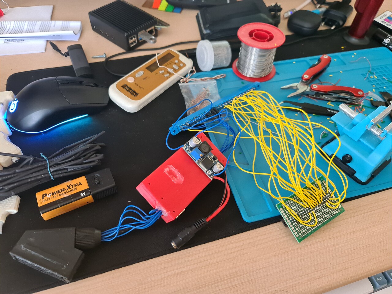
Pinout is pretty easy. Also the Jamma Connectors need to have both 5V and 12V input. So I used a LM2596 DC-DC step down module to output both 12V and 5V through a single 12V adapter.
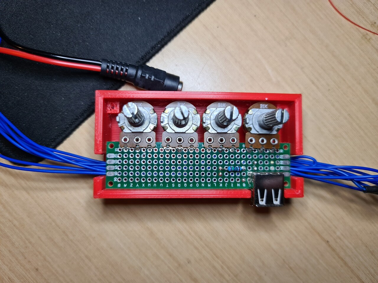
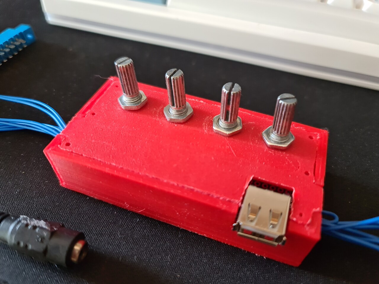
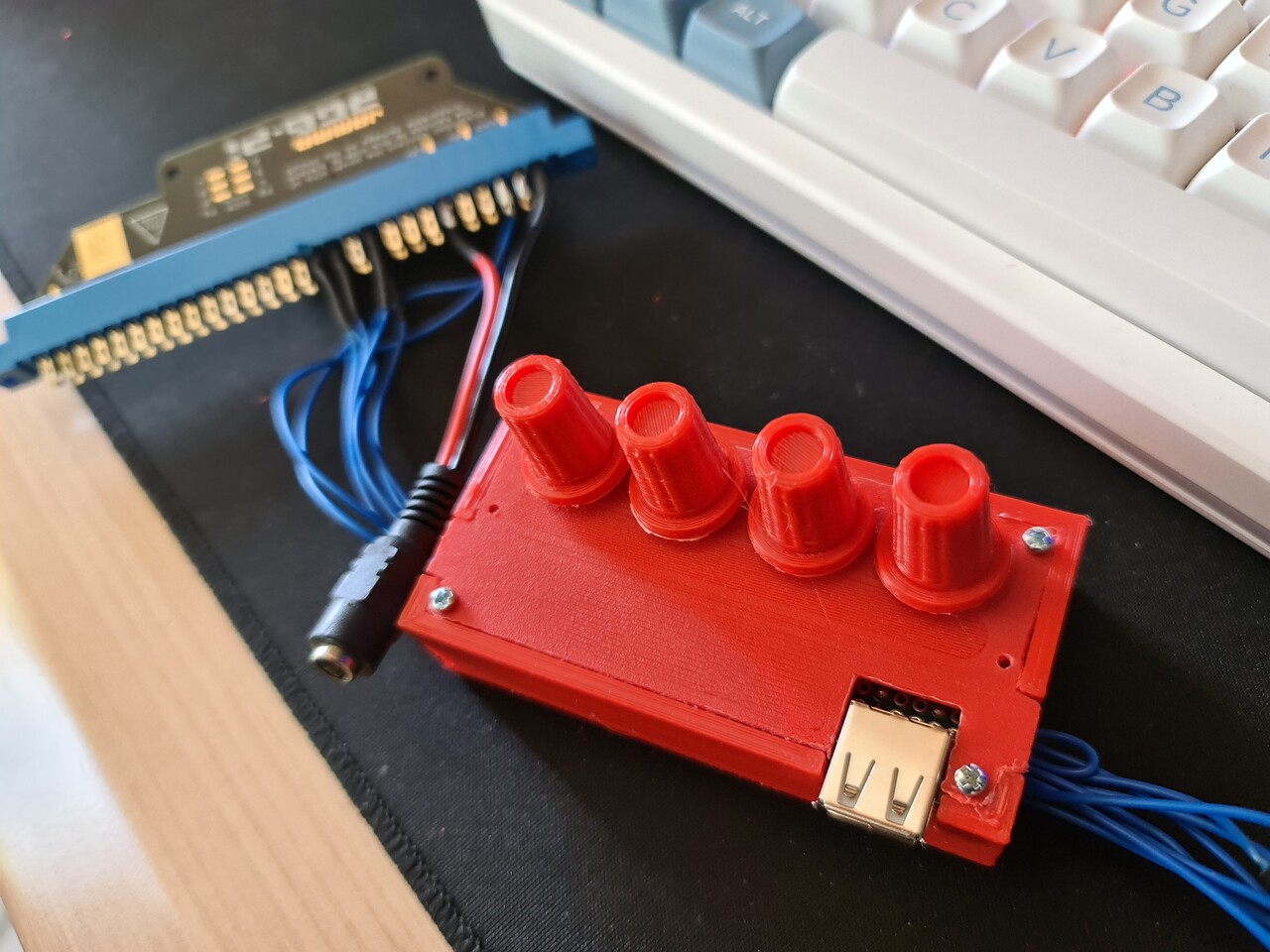
After testing the pinout, I added 4 potentiometers to adjust R G B channels for better picture and adjust the Sync signal for for supporting different arcade systems. After that I designed a case for that little adjustment board where I also added a USB port to connect additional devices in the future.
When I was testing this piece, I accidentally burned the IC on the RGB-Pi circuit. That IC was an amplifier for the sound channel. But this is only needed if you connect the cound channels on a blank speakers. Since I was connecting my sound output to a TV, and the TV has it's own amplifier on its board, I just shot circuited sound channels directly to sound pins of the Jamma edge connected, which means I bypassed that burnt amp IC.
3. Acquiring the TV
Now I had a fully functional convertion cable but I needed a TV. I checked the second-hand seller websites and found a cheap 14" CRT TV. The brand was the same, but the product model was different than the one my relative had.
4. Tests and Final Preparations
I tested the TV with my Jamma to Scart cable, and it even works with the original Neo-Geo MVS arcade board!
Meanwhile I bought an aluminum case for the Raspberry Pi 4 1GB version to work as a cooling system. I don't like fans, since it's not exceeding 55 °C with this case, I prefer using it like that.
4. Designing the Cabinet
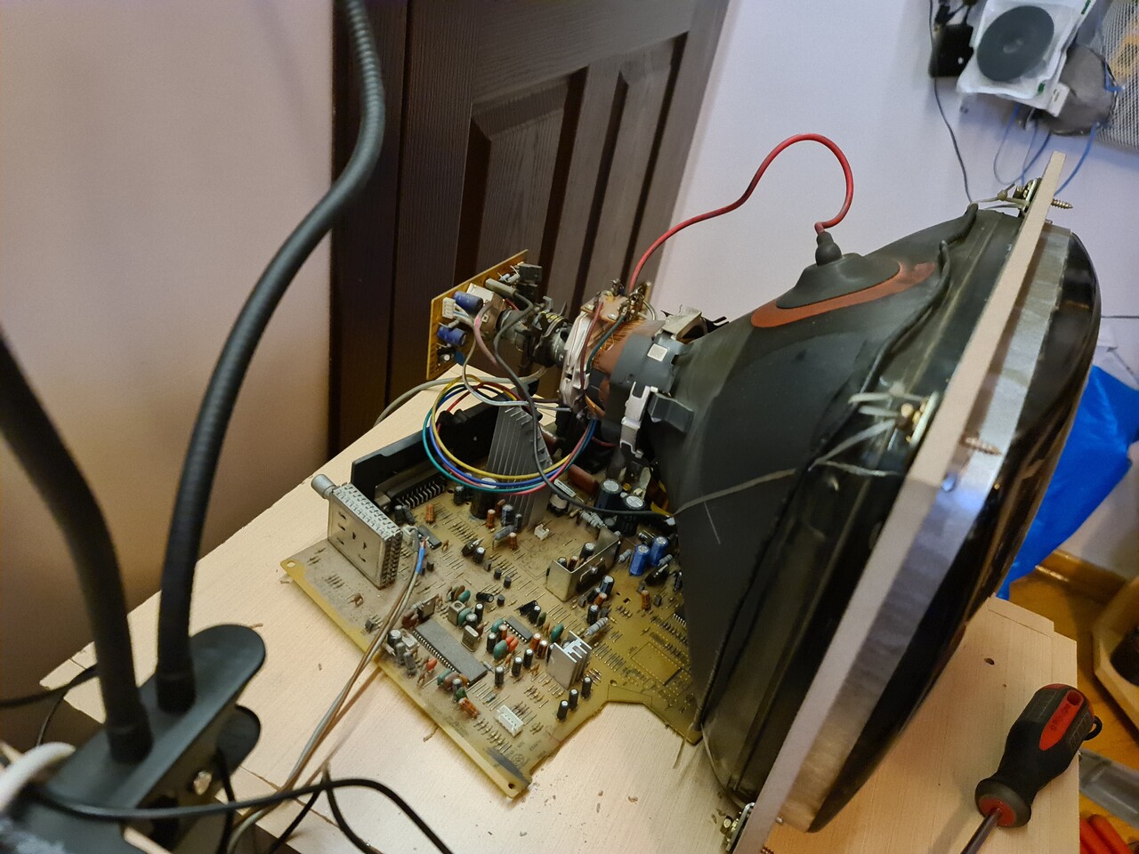
As a starter, I disassembled the case of the CRT TV and took measurements to fix it to the new case I'm going to design.
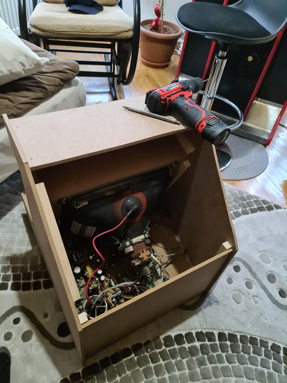
I measured the board of the TV as well. By the way, there is 20000 volts inside that tube. Normally you need to discharge it, I thought I did too, but turned out to be that I didn't! Luckily I didn't realized it by getting shocked but I it with my multimeter's NCV feature. You point the multimeter to an area and it checks that there is a high voltage there or not. So there was... Luckily I didn't touched anything while dissamblying and assemblying it :S
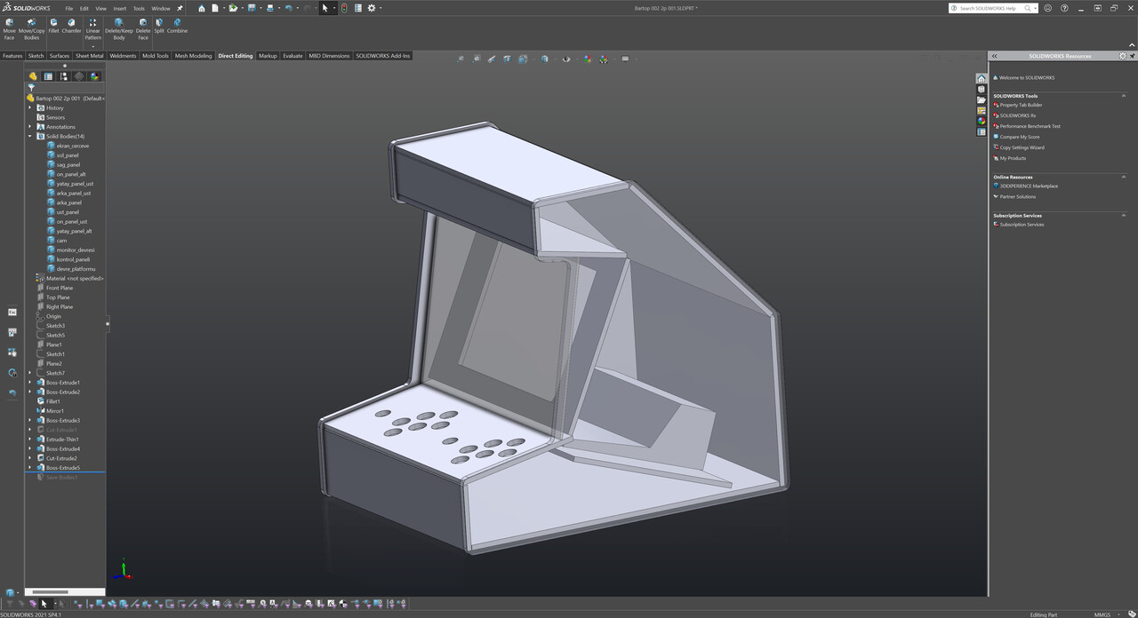
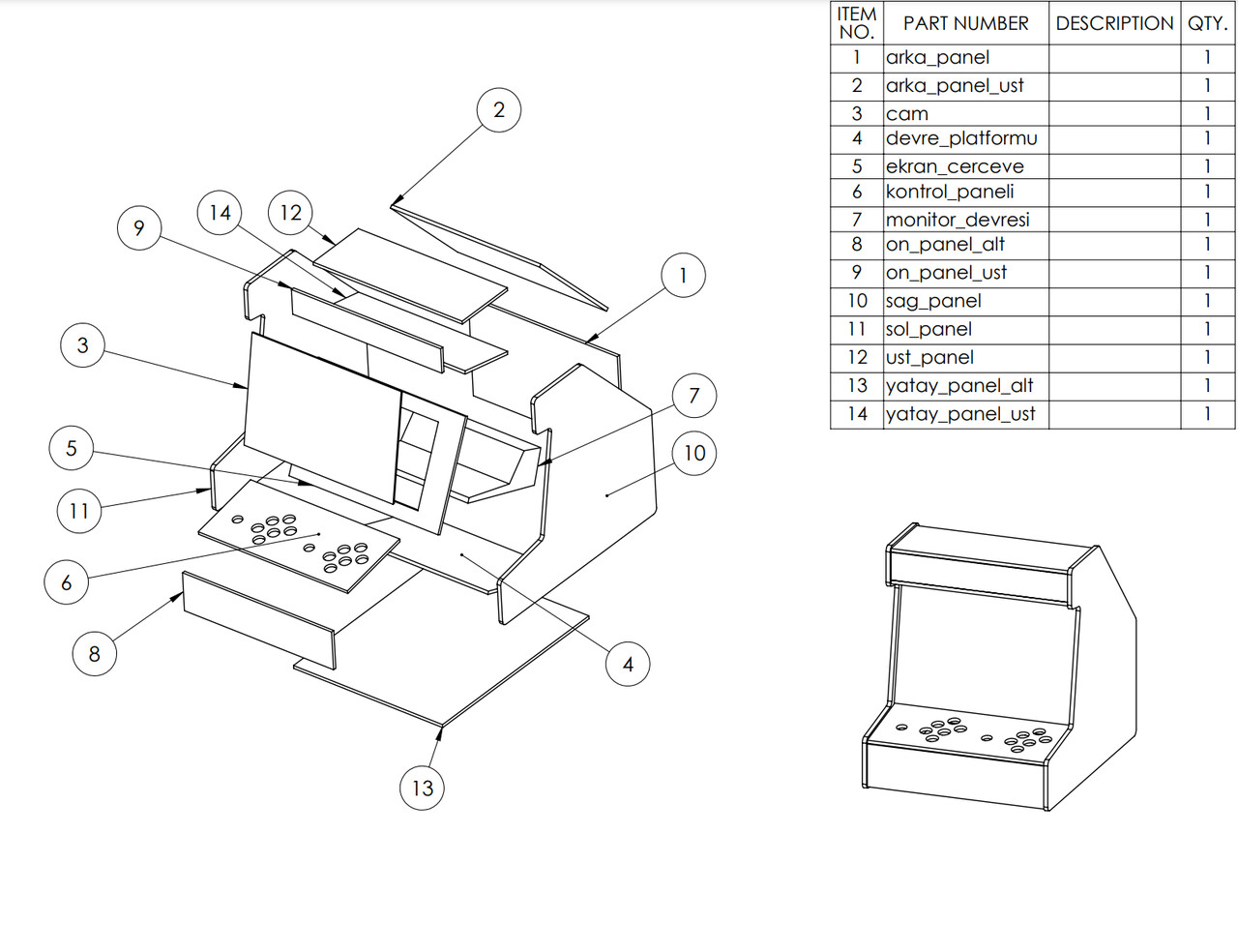
Anyway, I applied the simple measurements to my design, and defined simple boards to form my bartop design.
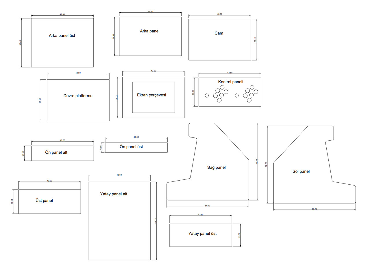
After creating the rough design, I go for the bill of materials (BOM) and created a list of panels to buy them from Bauhaus around here.
5. Constructing the Cabinet
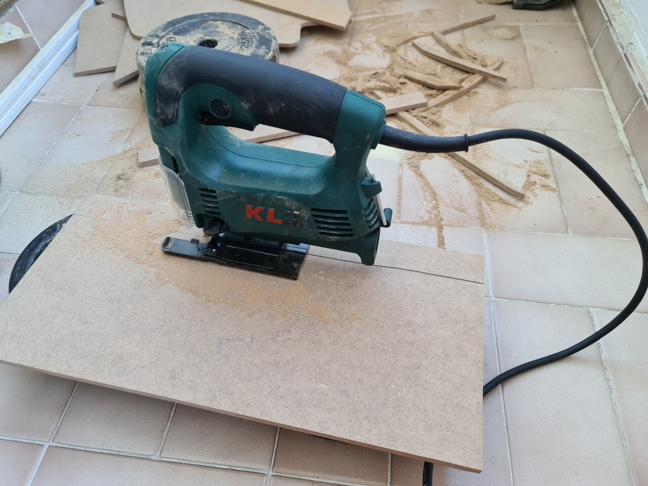
I ordered 8mm thick MDF plates as you see the dimensions right above. Bauhas can't cut these boards as their outline. They can cut only rectangle shape. So it was my job to cut these angular shapes by myself.
I started to cut the inside hole of the CRT panel first. It was hard to cut as a good linear way with Jigsaw tool but it will be easy to hide these mistakes.
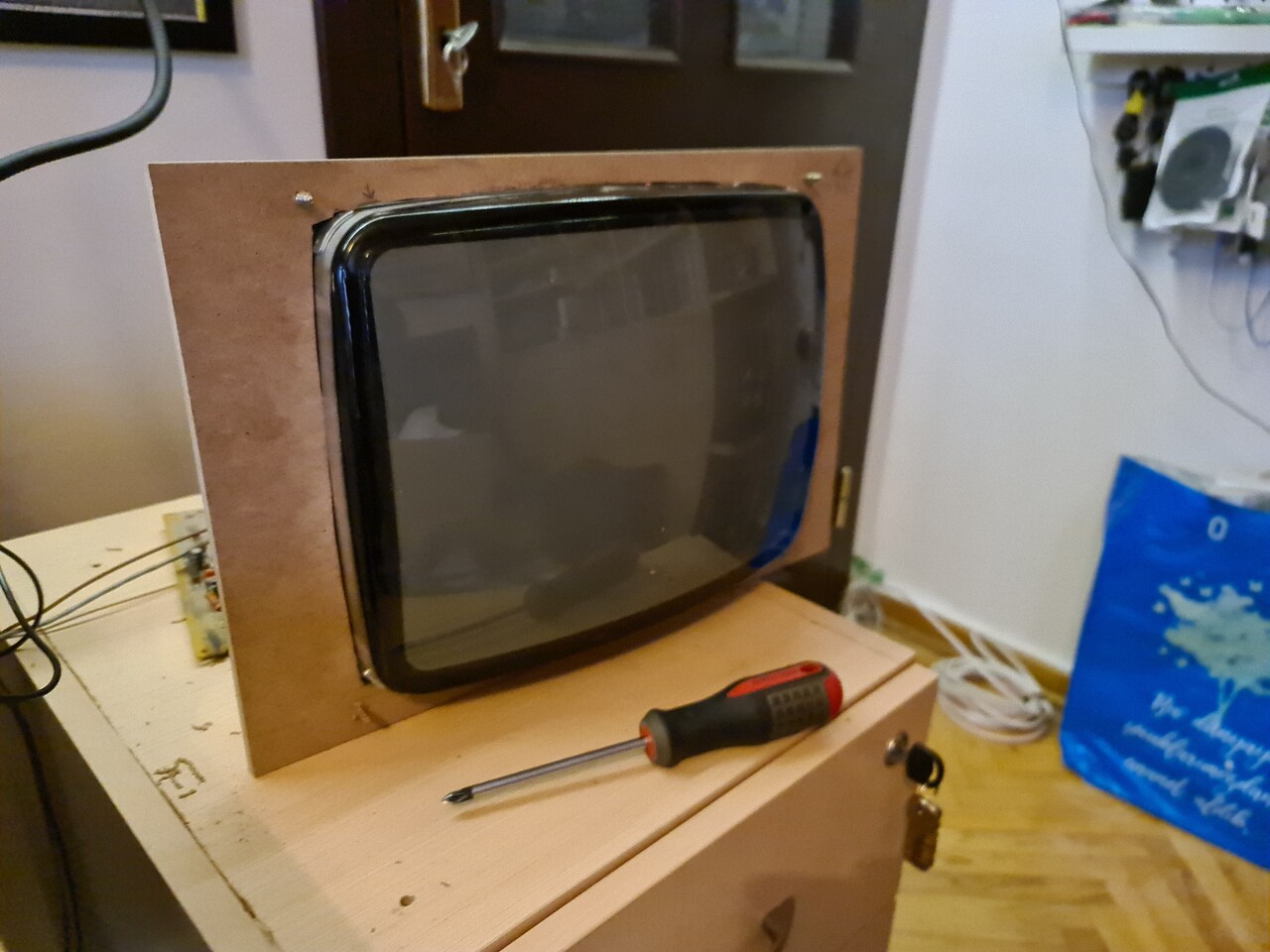
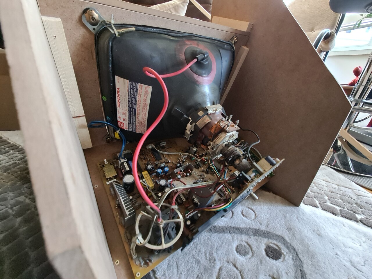
After cutting the front board, I fixed the CRT screen.
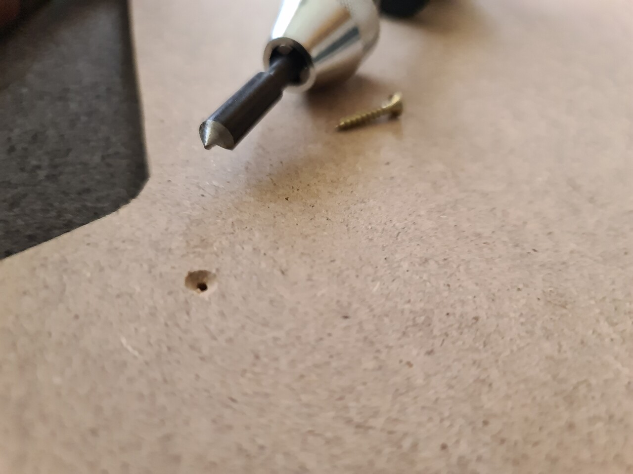
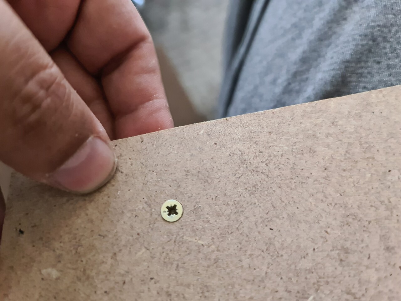
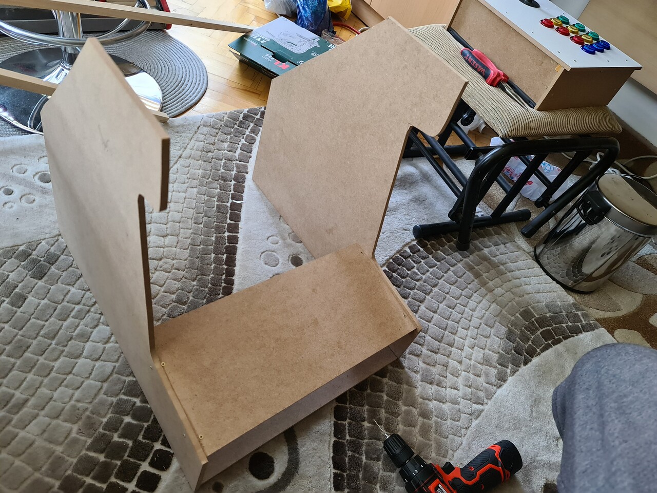
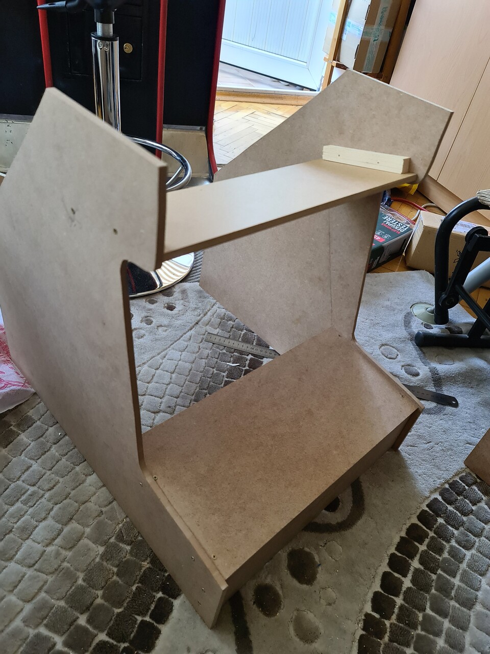
I cut the side parts as on my design and constructed the shape a little more. While I fix the parts with screw, I used a chamfering tool to make the screws planar with the surface, to get a better look.
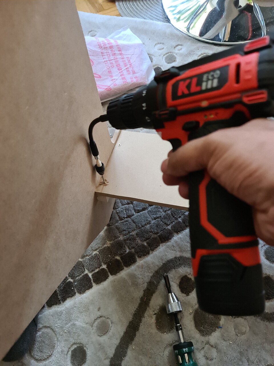
For drilling the hard positions, I used this flex screwing apparatus which was real helpful for those cases.
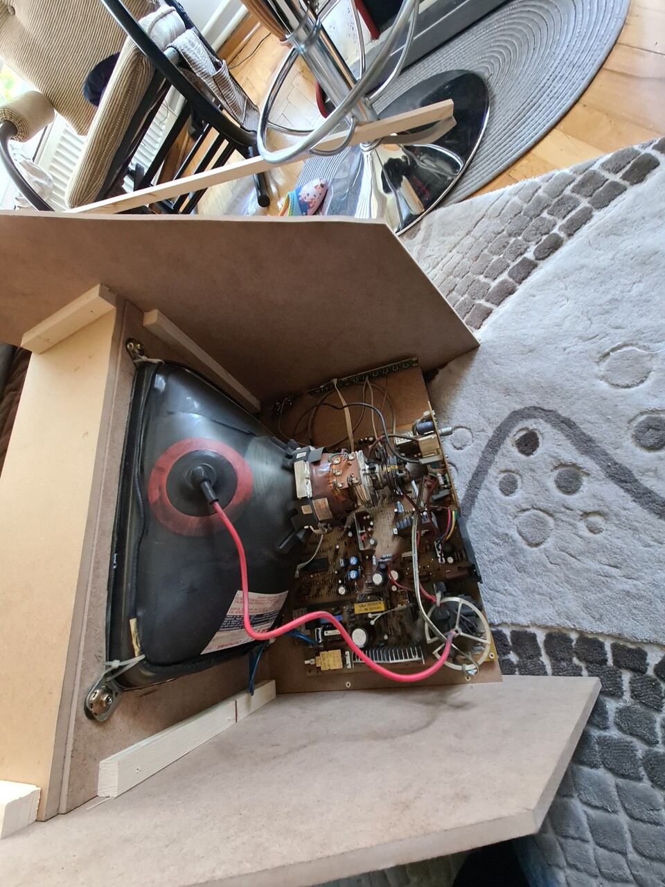
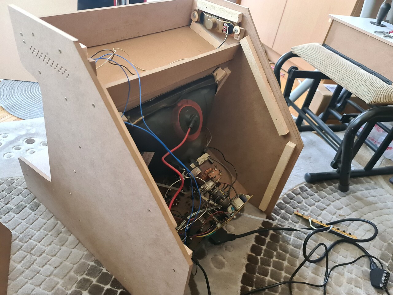
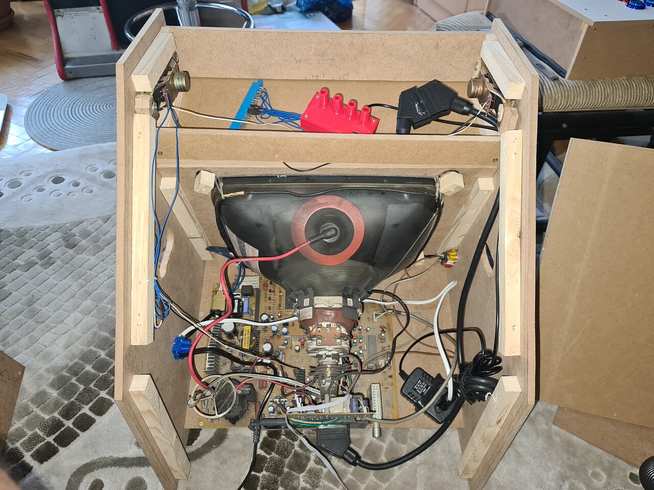
I moved on constructing the cabinet with the same approach and placed the screen as well.
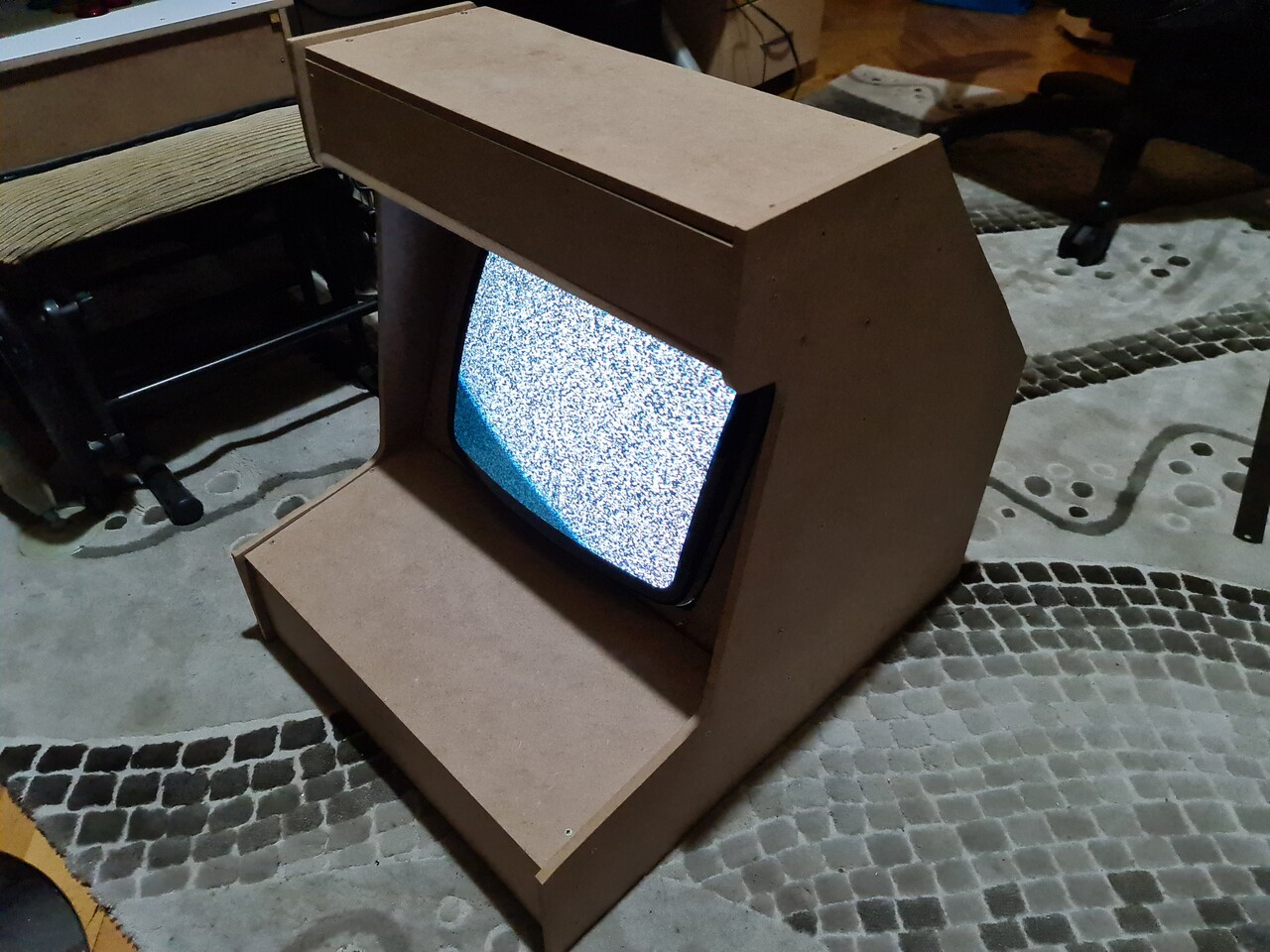
The most important part is since the screen is not discharged, I needed to close up the cabinet as soon as possible. So I fixed the back side boards and tested the system.
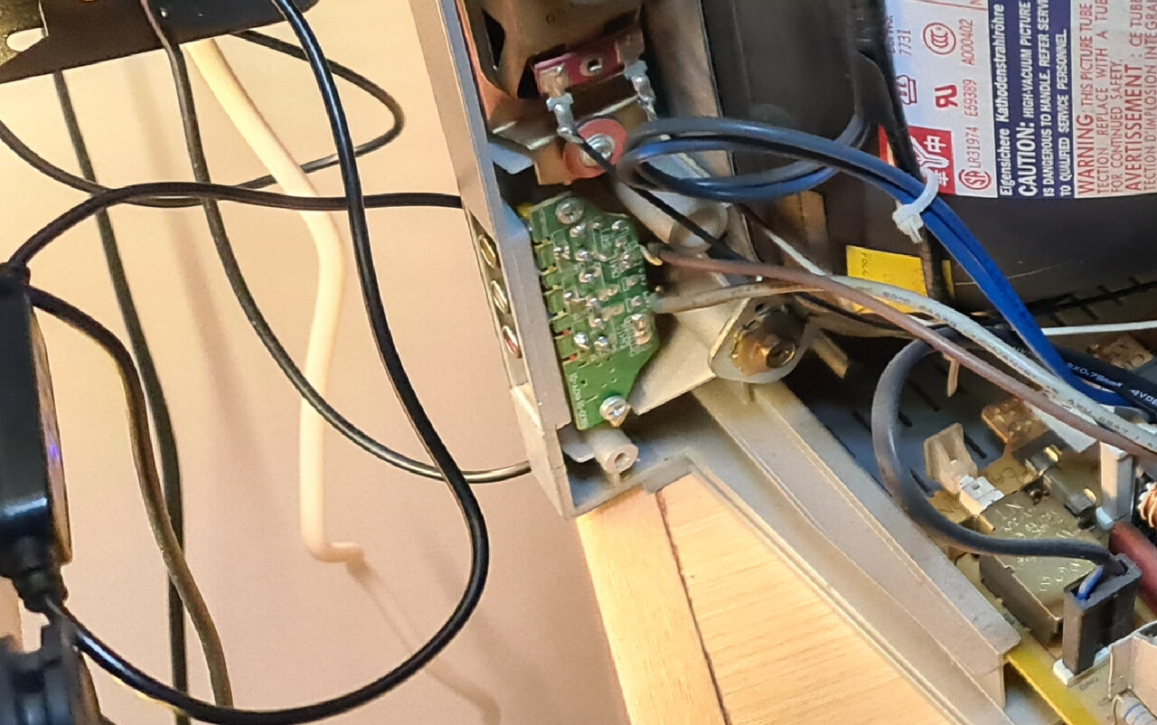
This TV system had a RCA input as well.
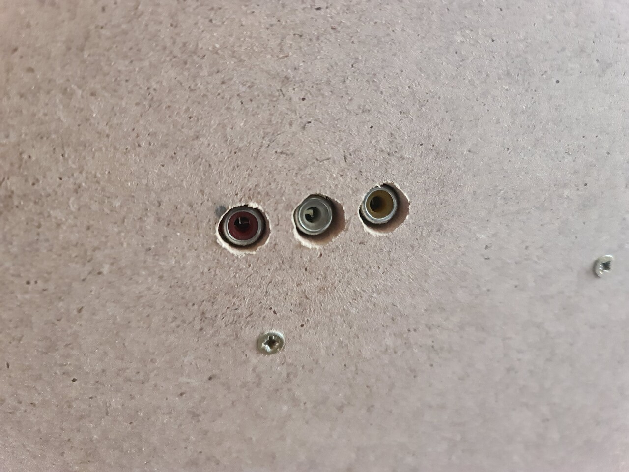
I moved that port to the side of my cabinet to use the system as a screen for other consoles as well. Also I could use this port to connect my Commodore 64 to the cabinet.
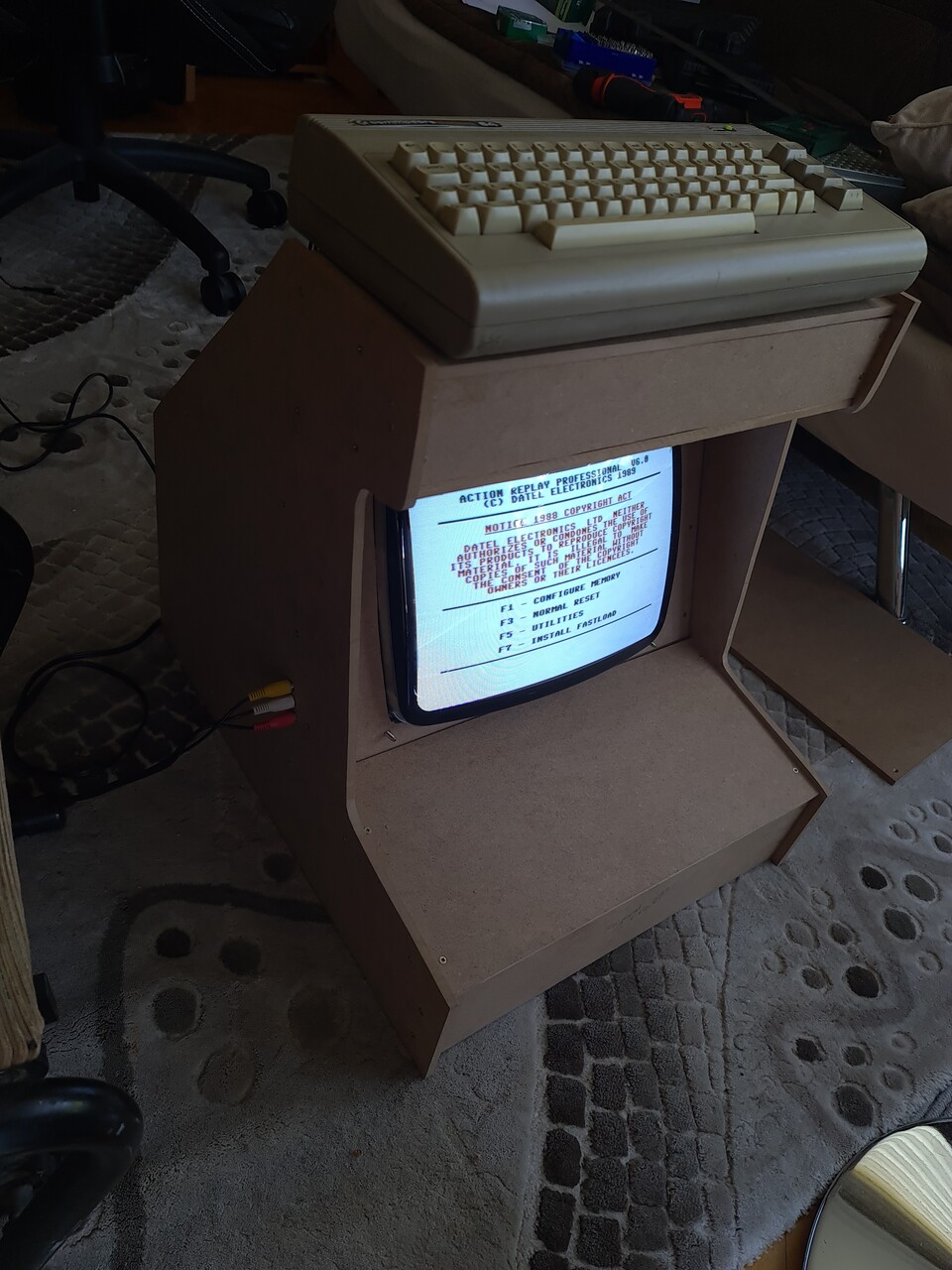
I tested the port with my Commodore 64.
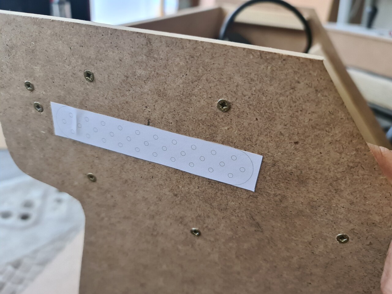
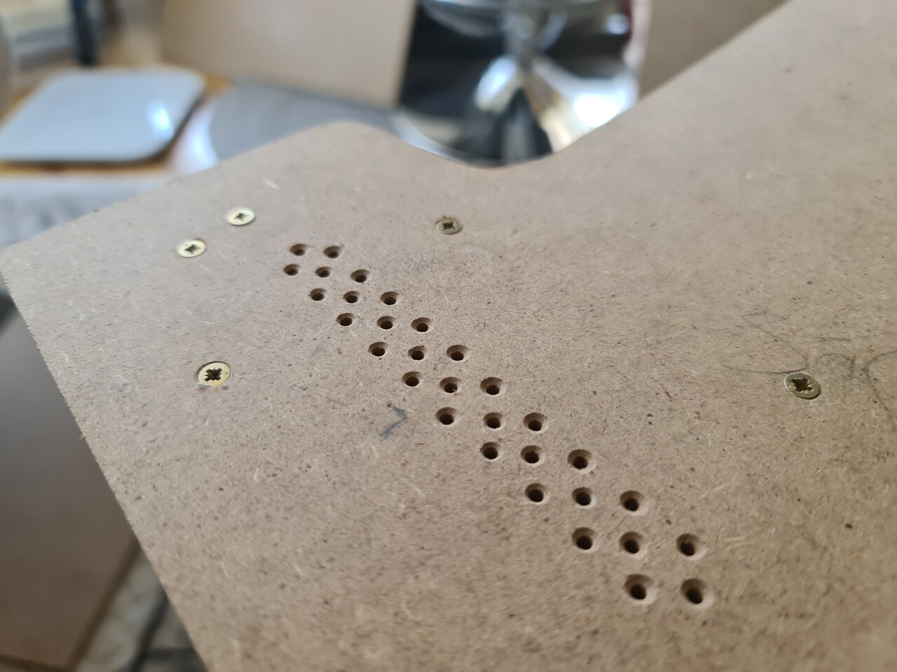
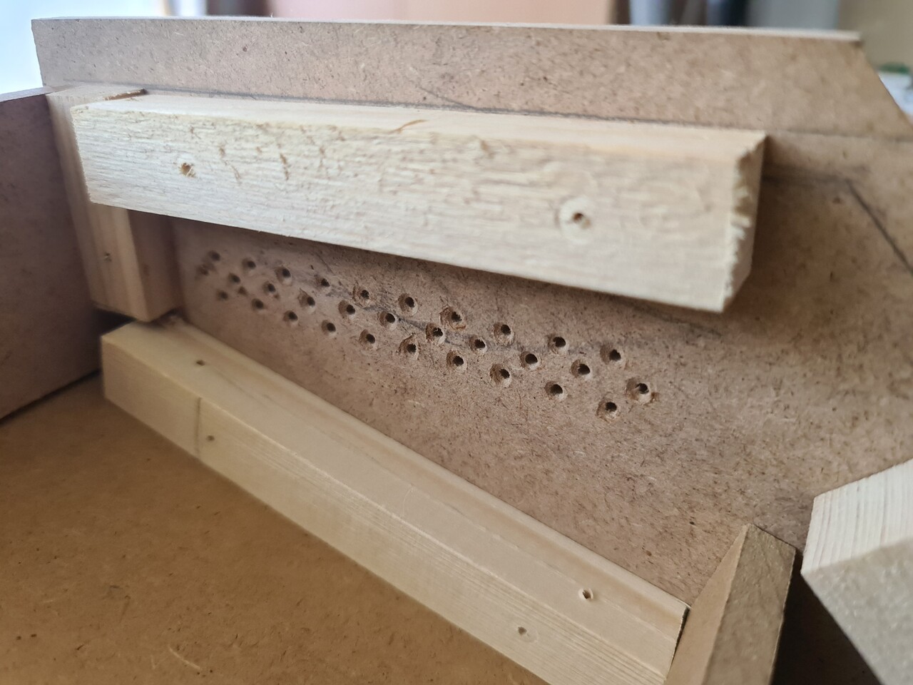
Next I placed the speakers of the TV to the side boards. And drilled holes for the sound to be not muffed. For drilling pattern, I created a quick placement and printed it to use as a template.
I used the same hole chamfering tool to make the holes look better. It was an unnecessary approach since I will cover that surface (including holes) with a stgicker folio.
And finally connected the speakers back.
I positioned the scart cable to the top and connected my jamma to scart assembly to that cable.
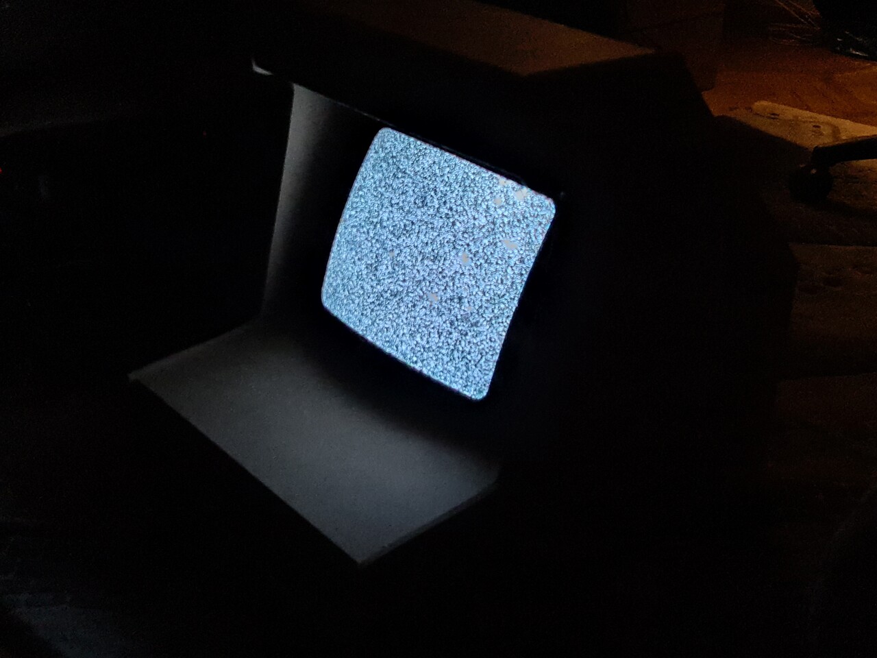
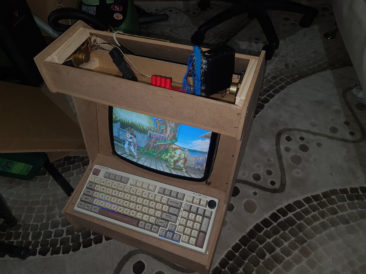
Testing the system and it's OK. That means I didn't broke anything with the TV while I'm mounting it to my cabinet. Using my fancy keyboard on bluetooth since I have no controller installed yet.
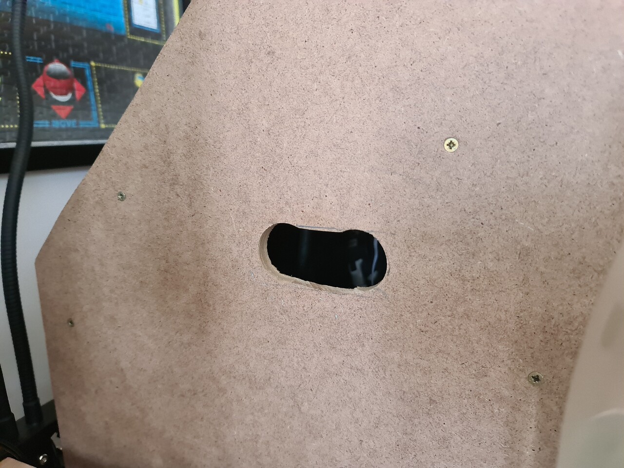
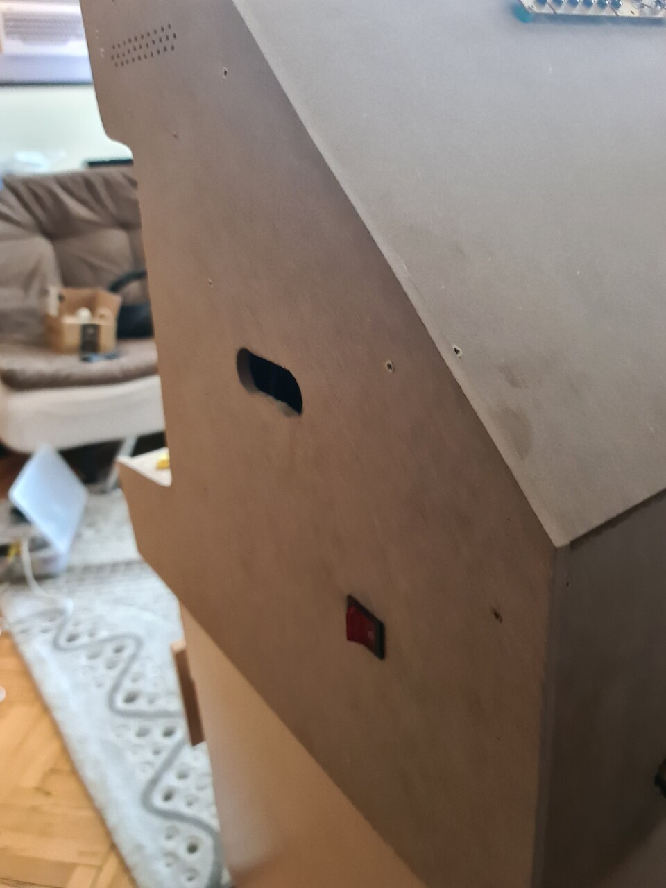
I added a slot hole to the both side for carrying the cabinet. I driled two big holes and connected two holes by a single saw. It's 17 kilograms so far. Can be carried easily by two people.
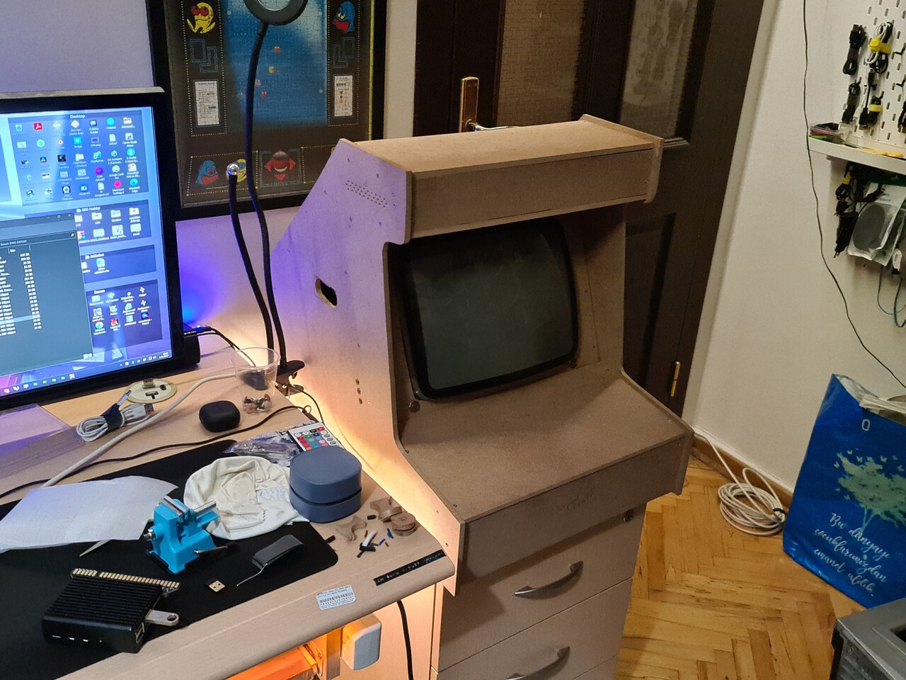
Shape is slowly forming.
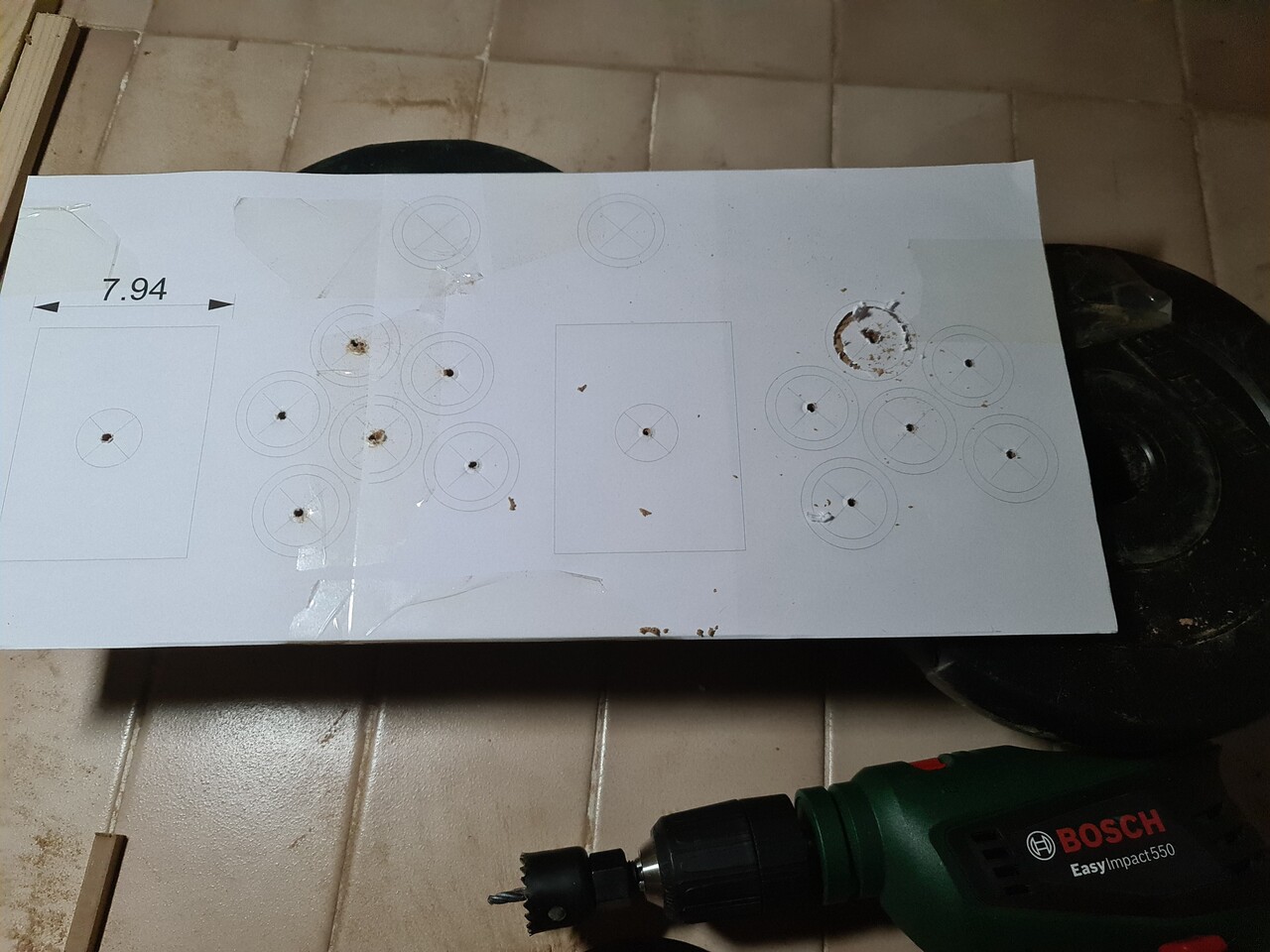
I printed the curve sketch of the holes for the controller board and I drilled the holes through it.
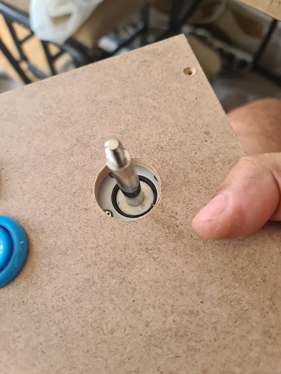
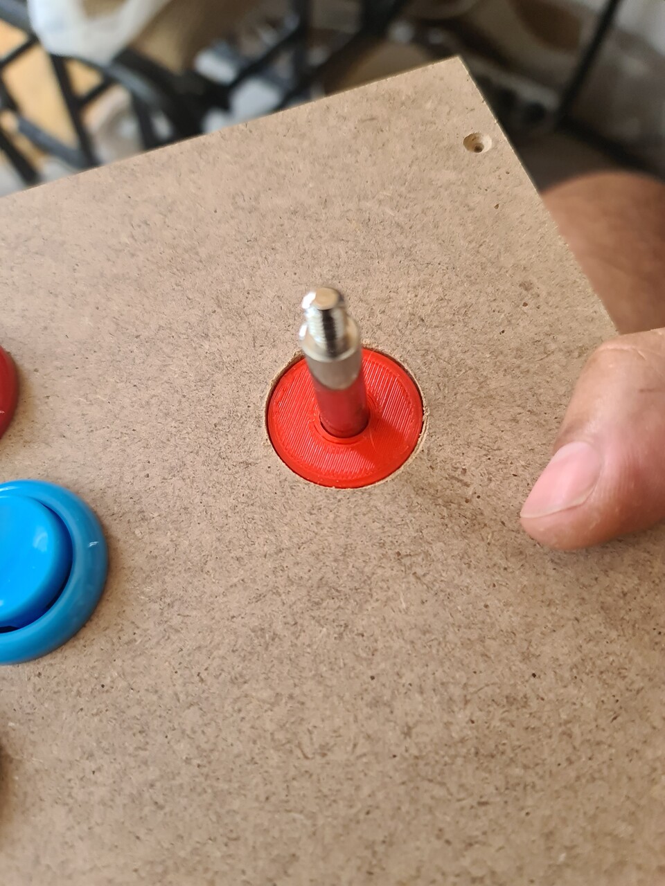
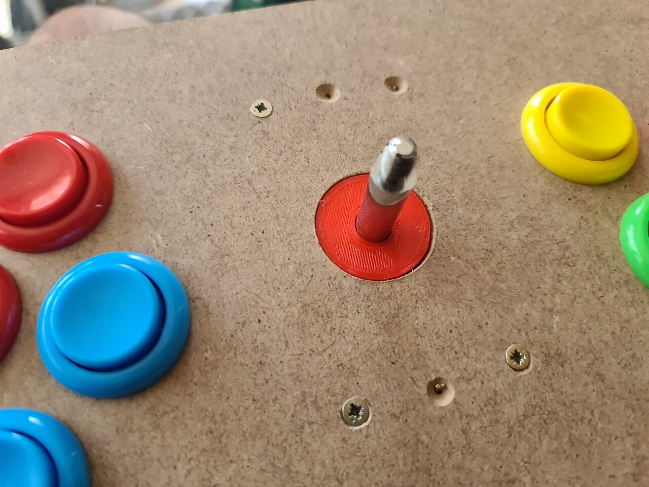
I screwed the controllers from the backside but before doing that, I 3d printed an alignment ring to locate the controller centered with the hole on the controller board.
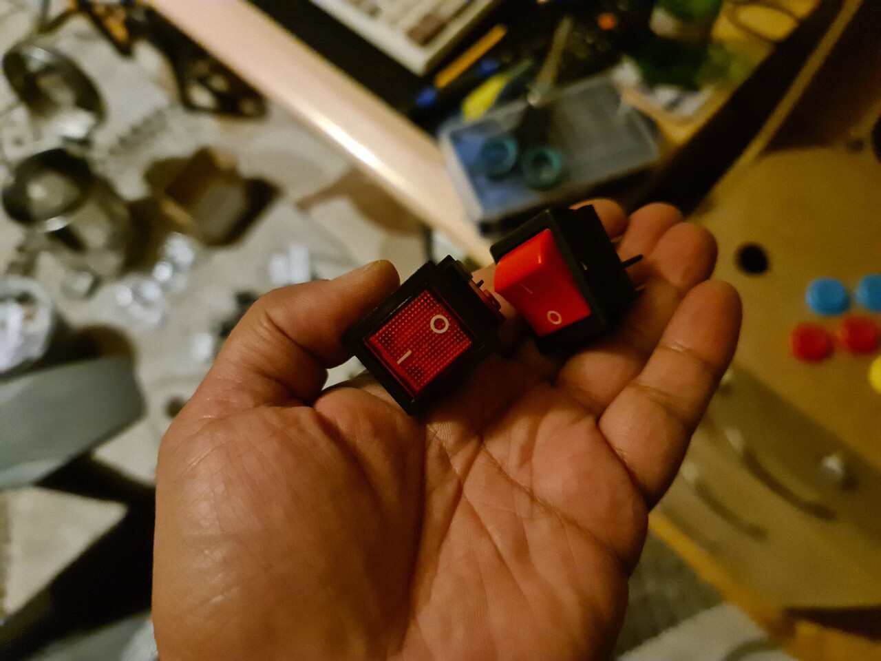
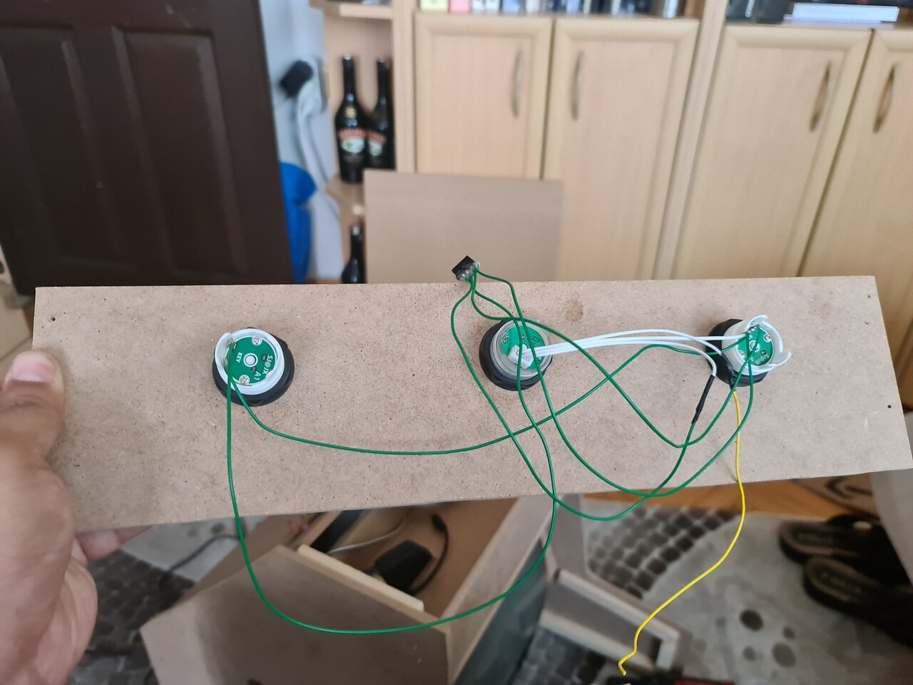
Next I connected and soldered a 220V on/off switch to the right side.
This is how the cabinet looks so far.
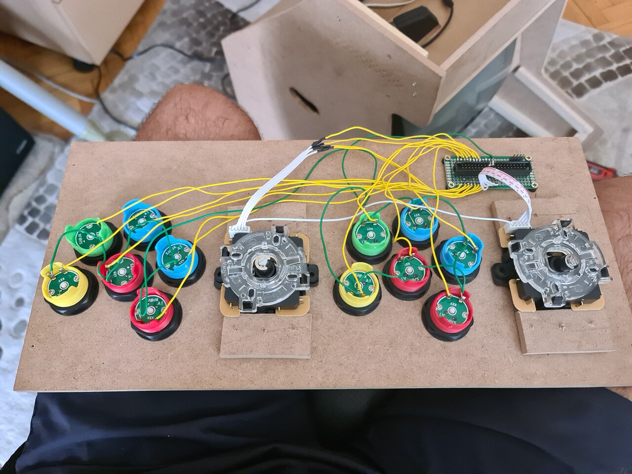
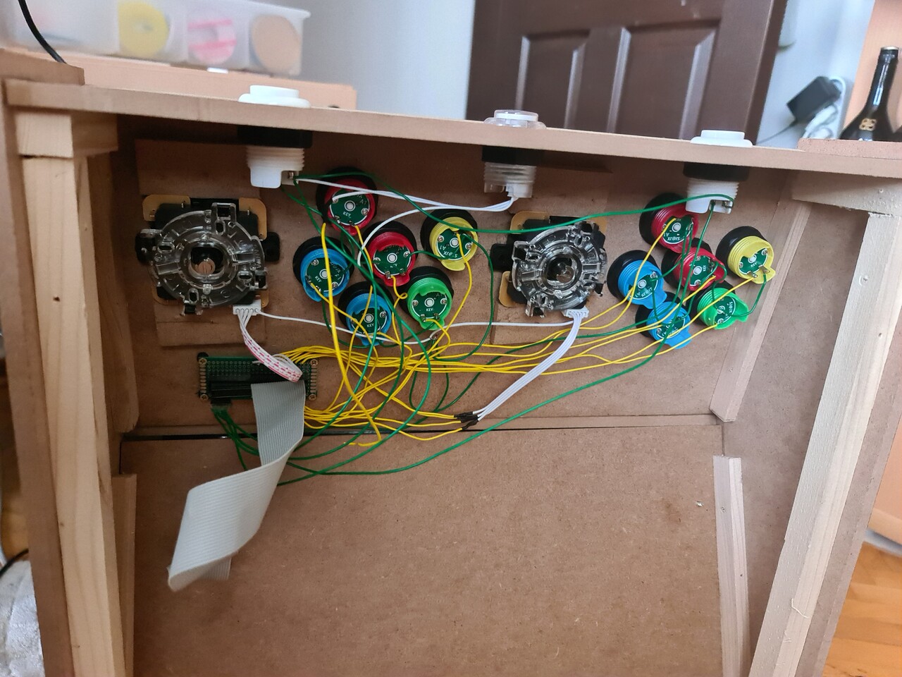
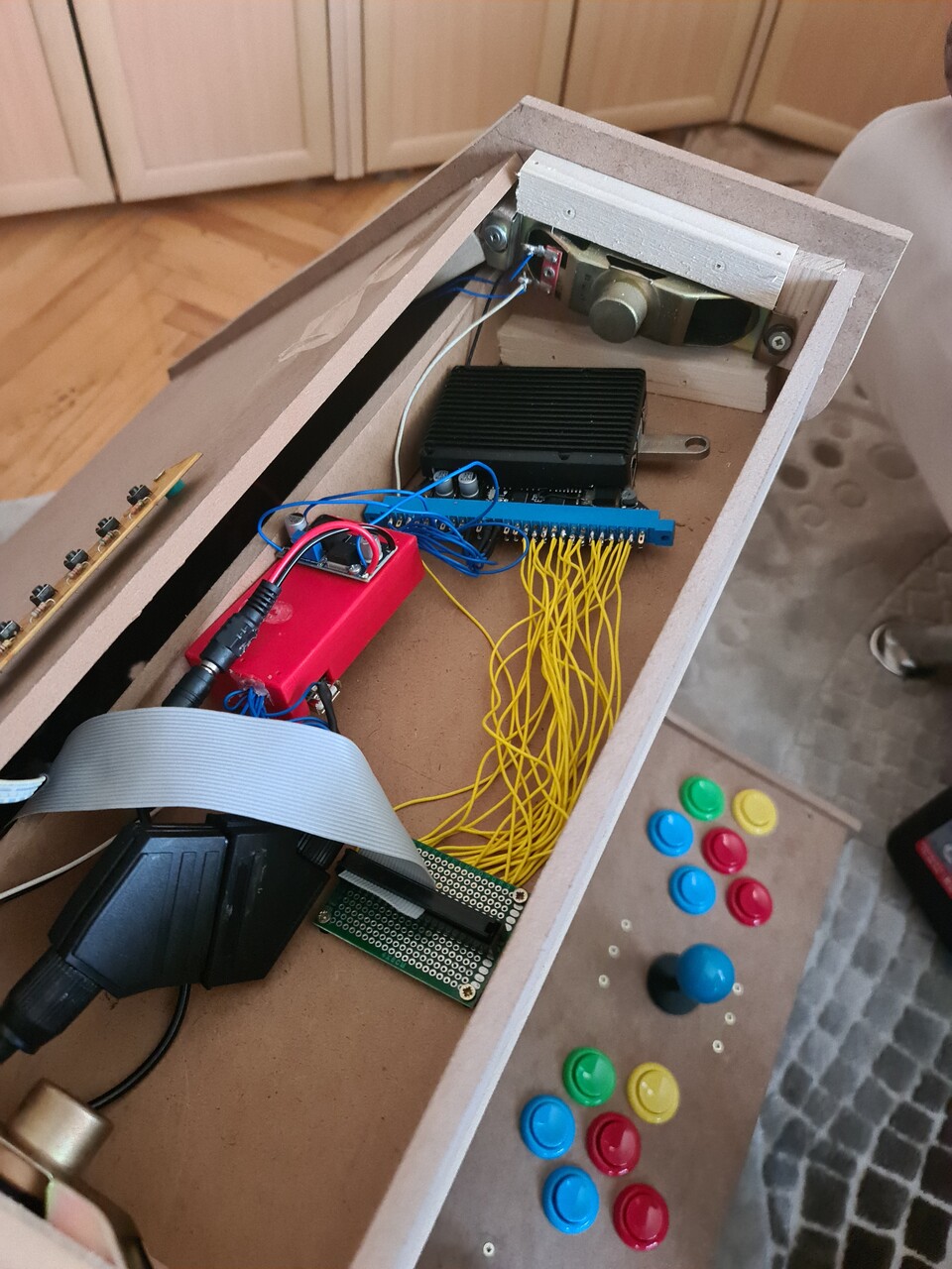
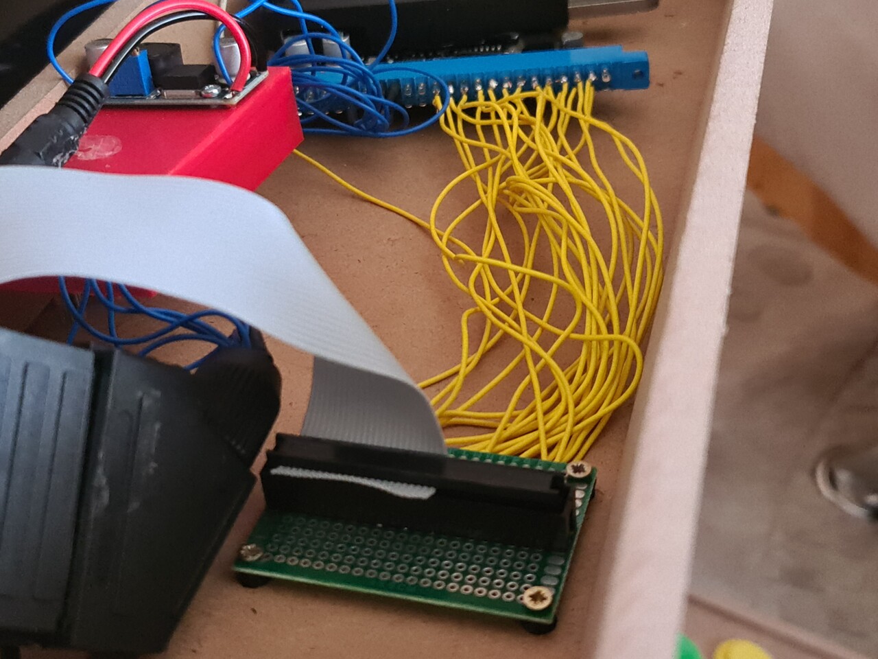
Since I mounted all the buttons and the joysticks, now it's time for cabling. I made the cabling by having the ability demount the control panel entirely. So I added connectors to the both cabinet side cables and control panel cables. I soldered a 40 pin connector to the controller board so I can connect the pins by a flex cable from controller panel to Raspberry Pi.
This is how it's mounted to the cabinet. I will connect the 40-pin flex cable to the jamma part.
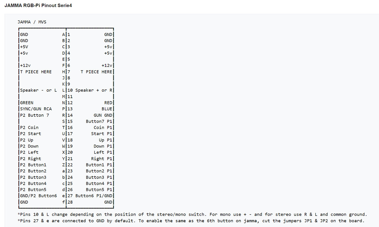
Next I soldered cables to jamma for Player 1 and Player 2 controls, and I terminated these cables with another 40-pin connector.
I followed this diagram and applied it to jamma connector for the controller pinouts. Source: https://www.mortaca.com/rgb-pi/wiki/index.php?title=RGB-Pi_JAMMA_Installation/en
Now the controlers are ON!
Let's play some Metal Slug!
Now it's time for cosmetic details. See you on the next part.
P.S. This post was actually one piece. But Artstation gave some errors about the length of the blog post. You can check the 2nd part by this link:
https://www.artstation.com/blogs/blockmind/Y1gw/making-of-a-crt-tabletop-bartop-arcade-machine-part-22
