Hi everyone. A while ago I bought a second hand 10 inch CRT TV from a seller. Considering the size of it, it was looking great to make a CRT arcade cabinet with that one.
- My Previous Cabinet Projects
Previously I made a cabinet with an 8" LCD screen. That was a portable, small, 1 player good cabinet. Only downside of that one was it has LCD screen, not a CRT.
https://www.artstation.com/blogs/blockmind/PvdE/making-of-a-tabletop-arcade-machine
Next I acquired a 13" CRT TV and made a cabinet with that screen for 2 players.
https://www.artstation.com/blogs/blockmind/EgoA/making-of-a-crt-tabletop-bartop-arcade-machine-part-1-2
https://www.artstation.com/blogs/blockmind/Y1gw/making-of-a-crt-tabletop-bartop-arcade-machine-part-22

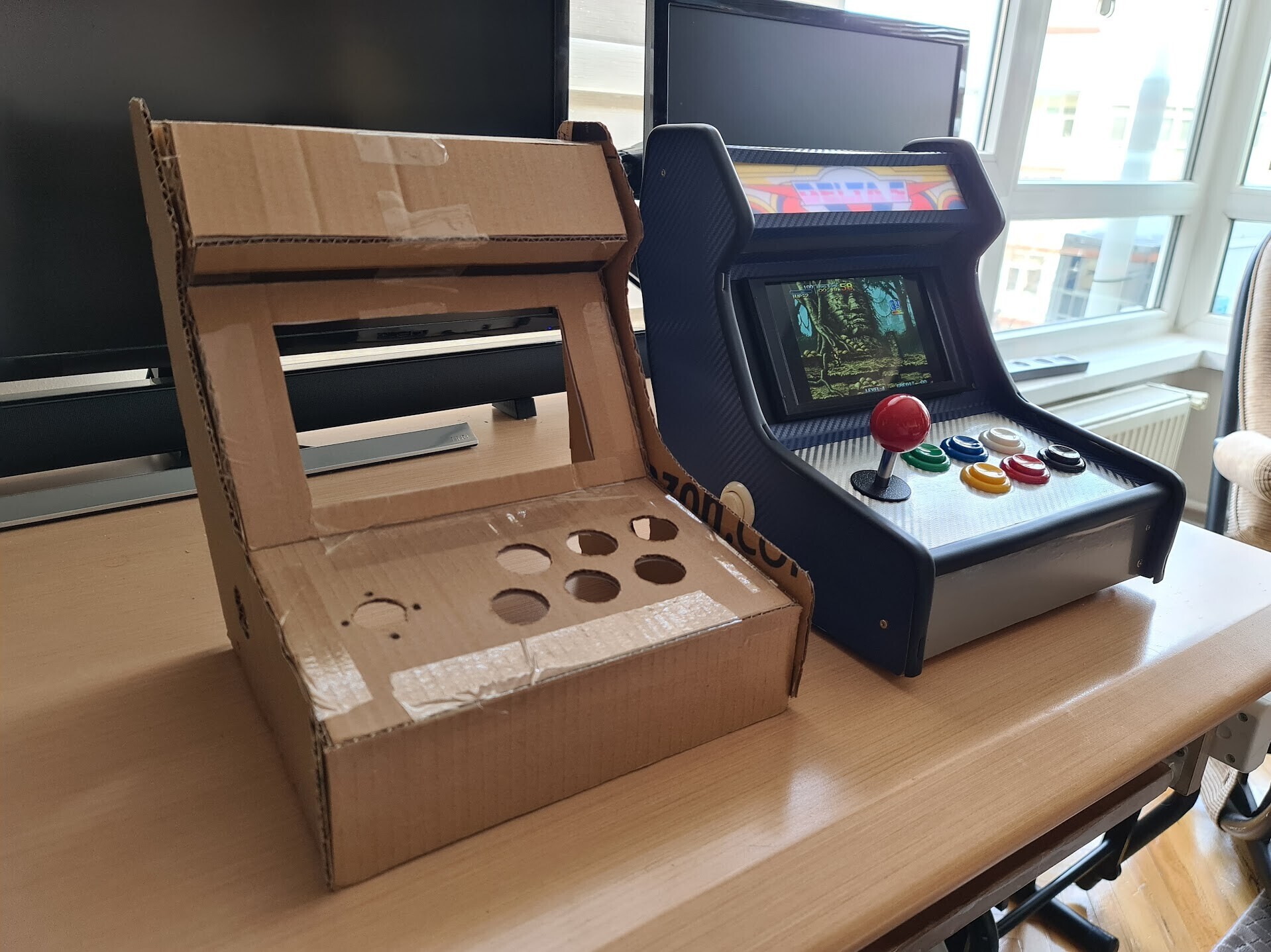
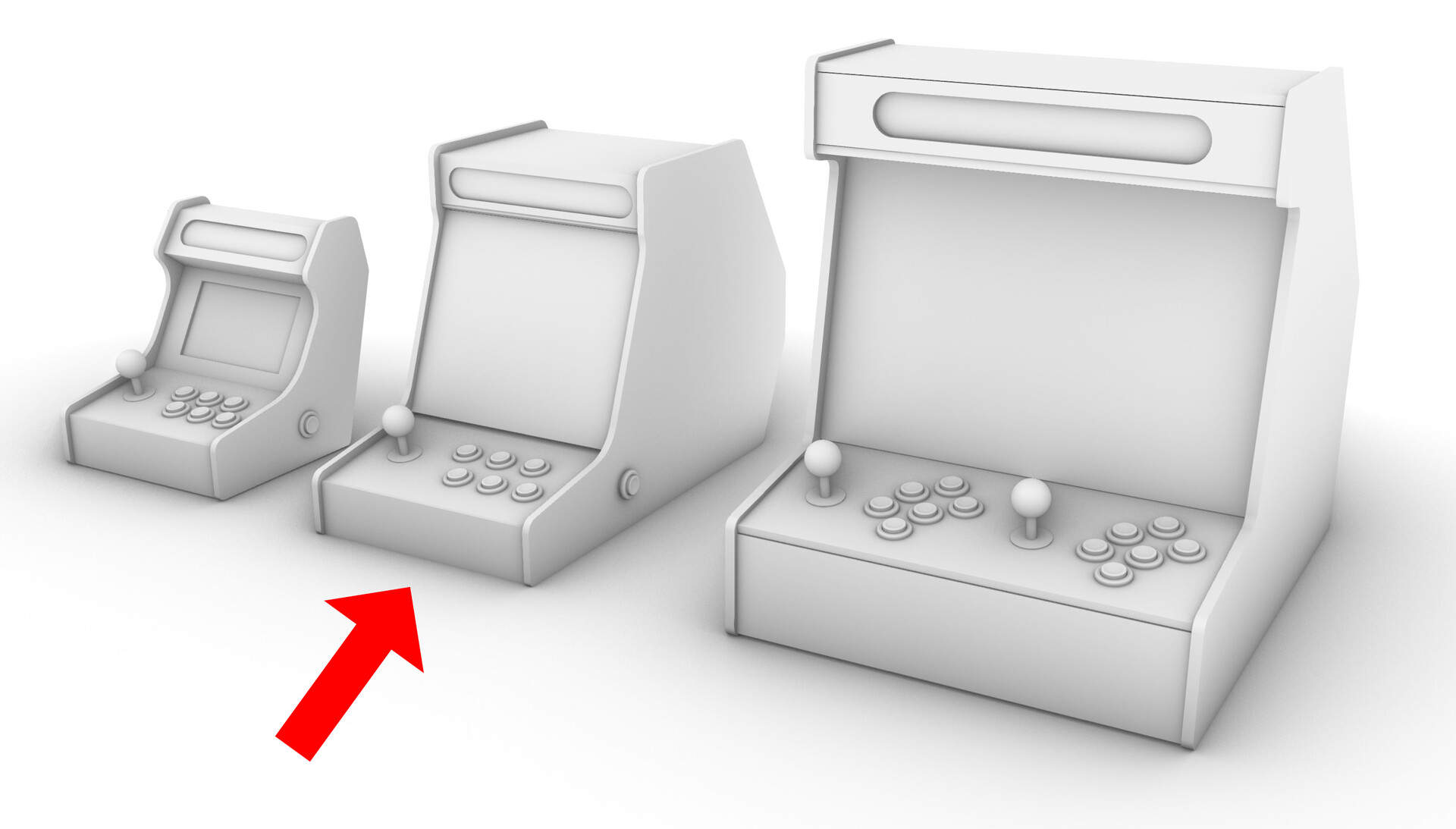
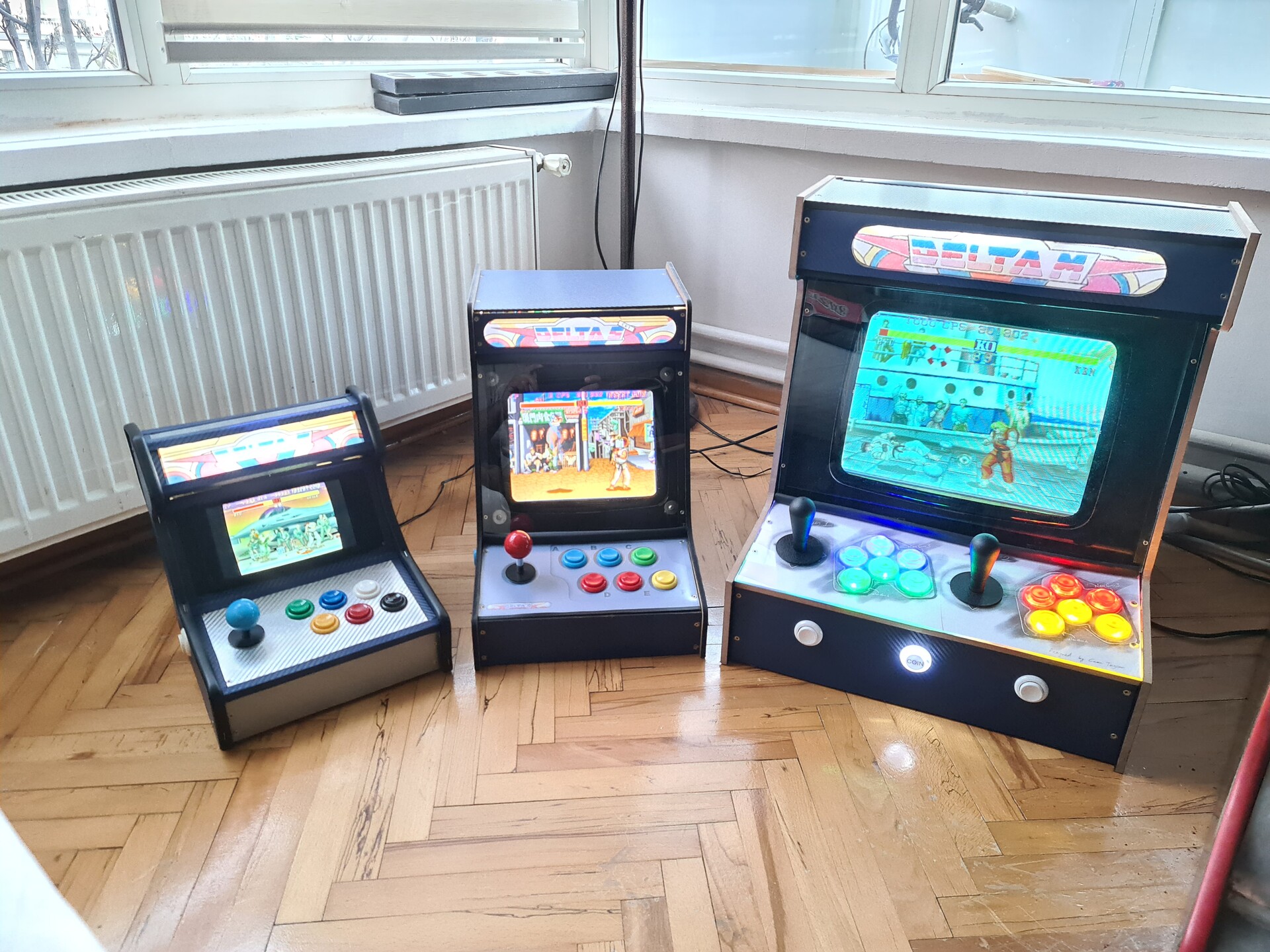
The new one is the middle one on this render:

2. 10" TV and the Idea
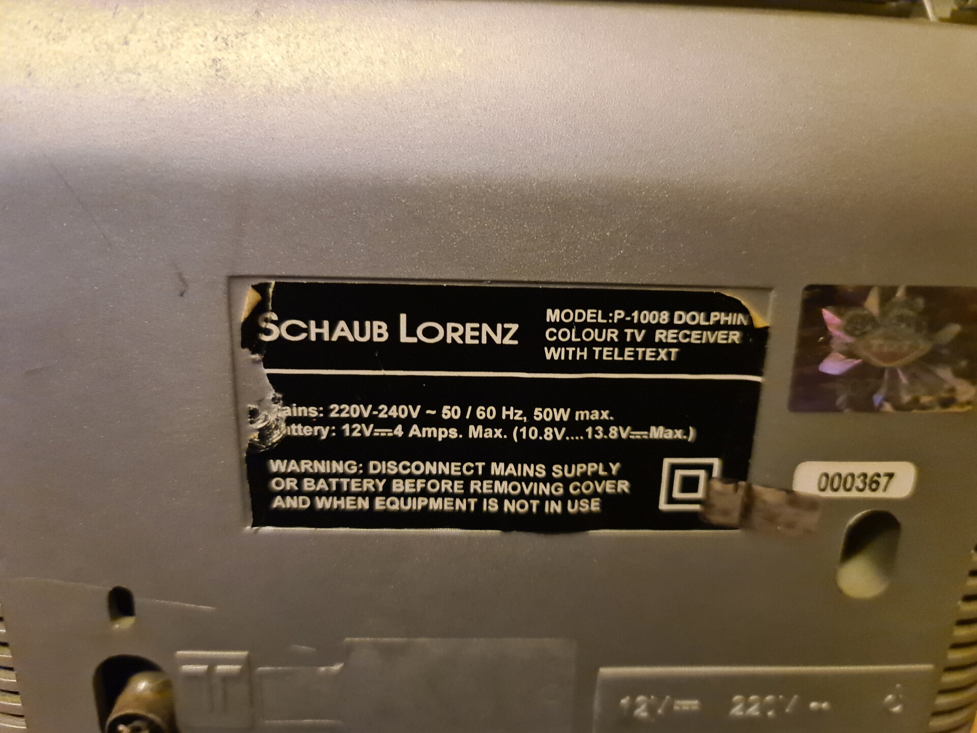
The TV a got is a 10" Schaub Lorenz with a SCART input. I heard the name for the first time.
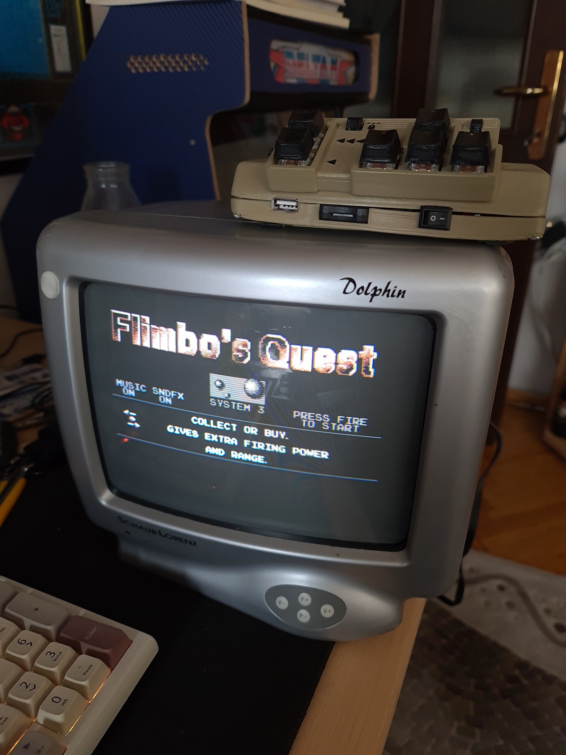
The most important feature of this TV is that it is a multy-sync TV that supports refresh rates from 50 hz to 60 hz. This is important since many arcade games have variated screen refresh rates like 54hz, 57hz etc.
Since it has a small size, the phospor pattern is so visible but as a good news, scanlines are less recognizable.
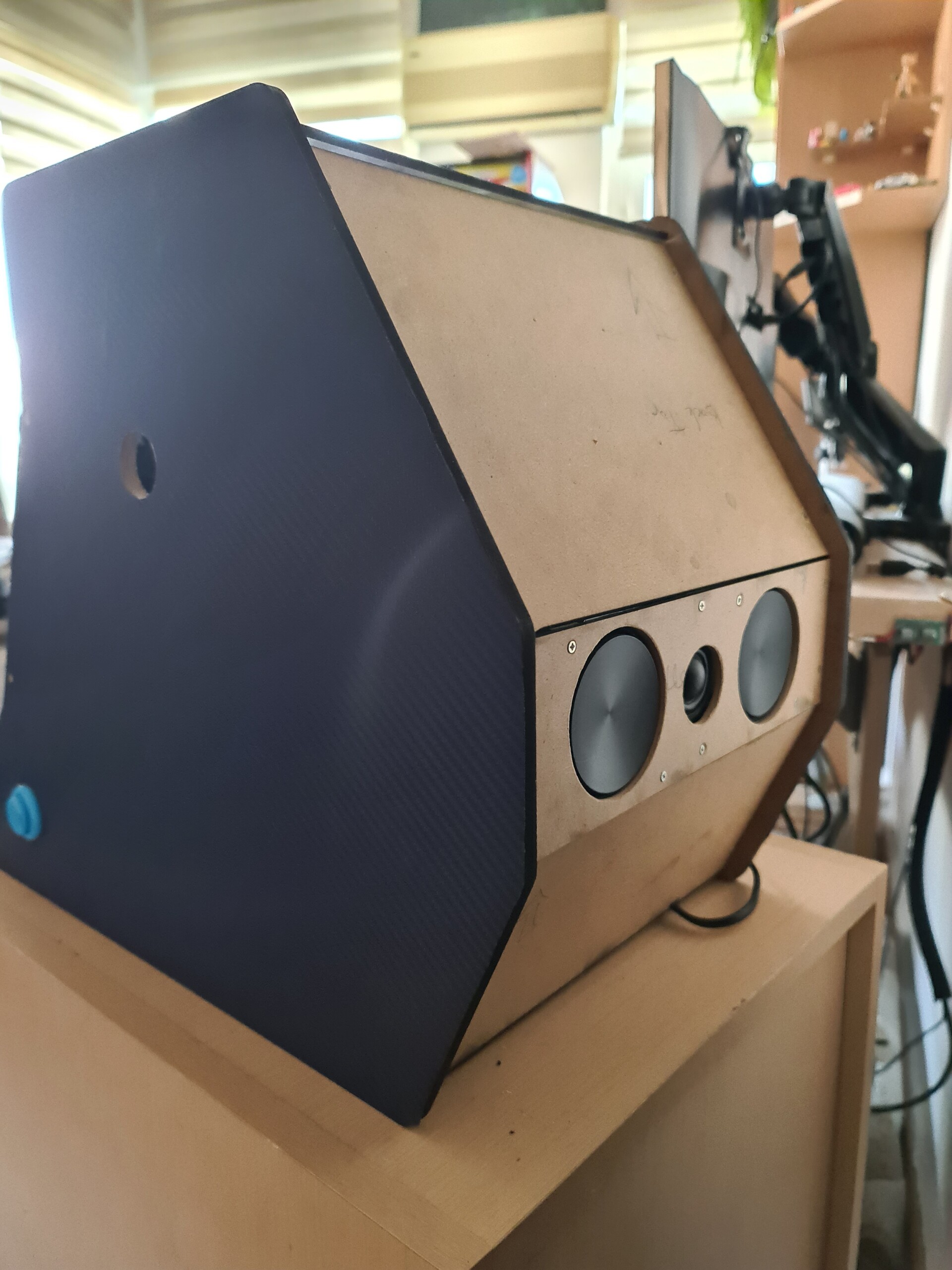
3. Making of the Case
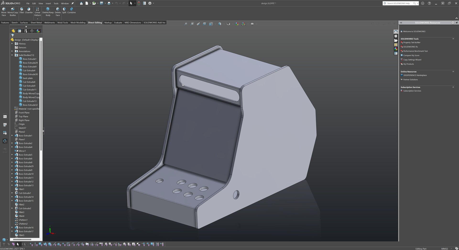
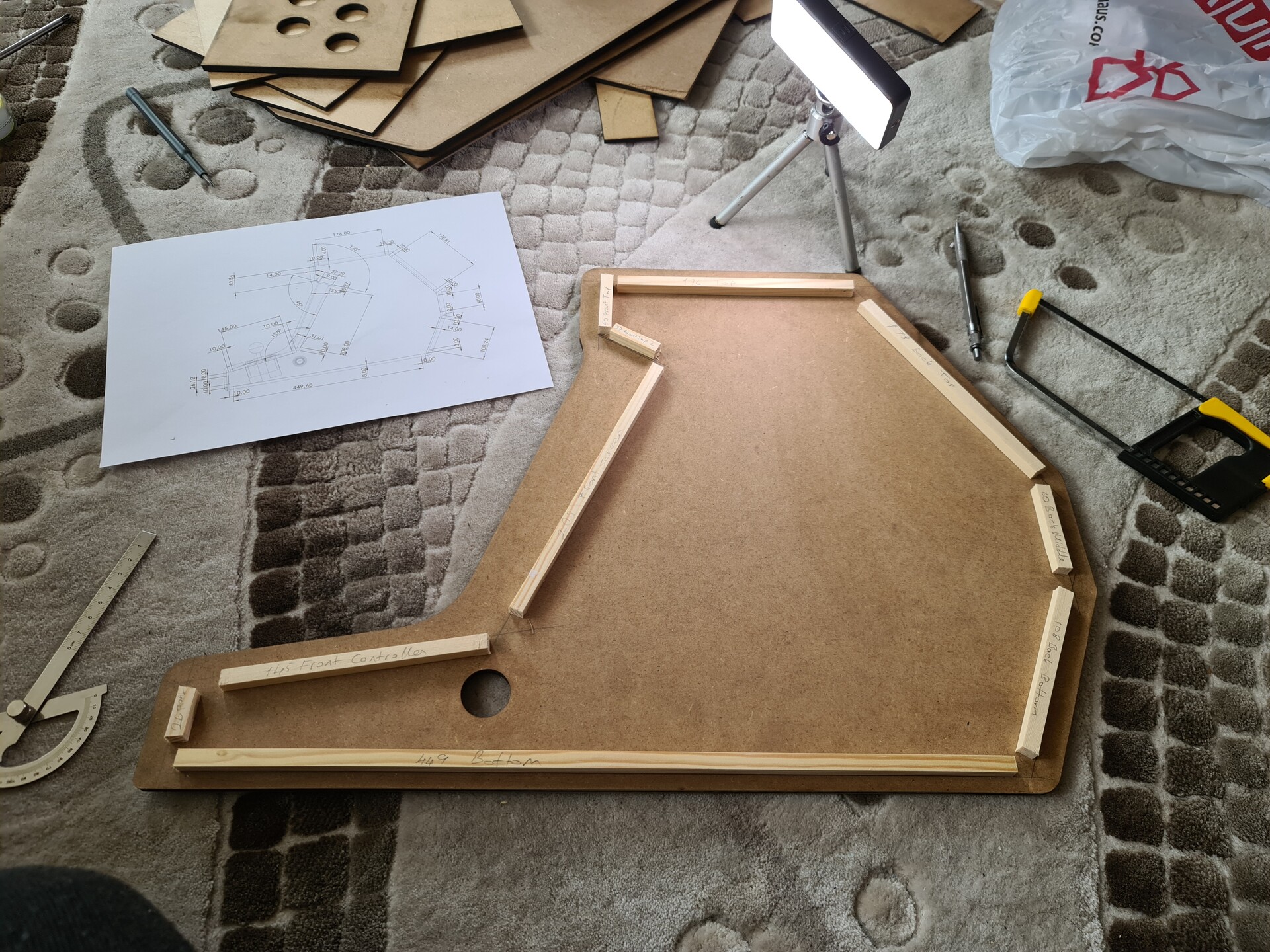
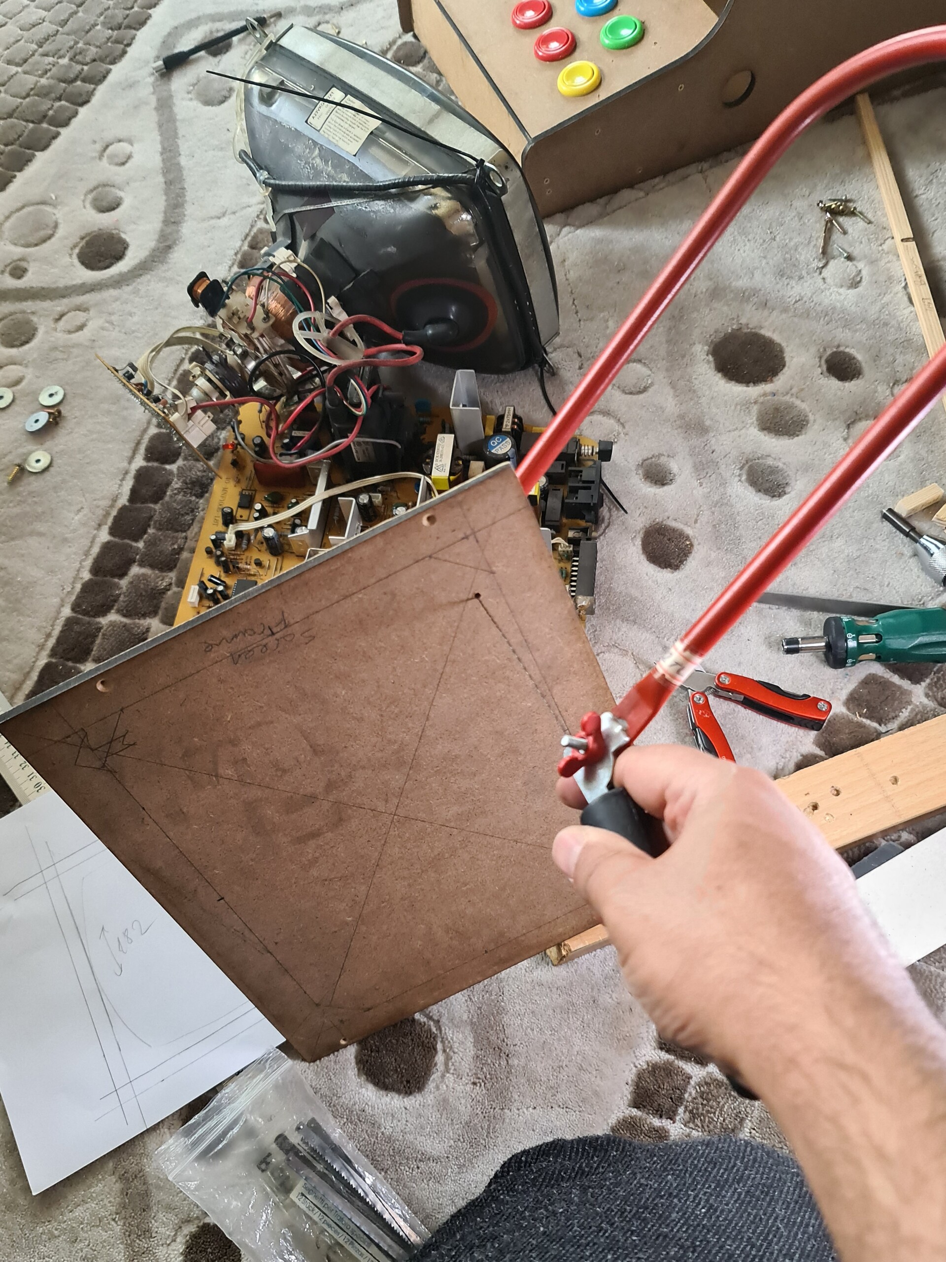
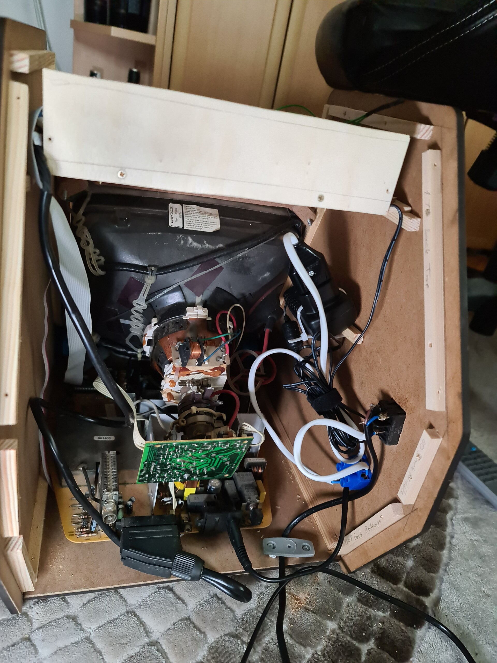
Before getting into wood panels (actually I use MDF panels) I disassemblied the TV and quickly measured the outer dimensions of the CRT tube. This way I made a quick design with Solidworks to fetch a cut list.
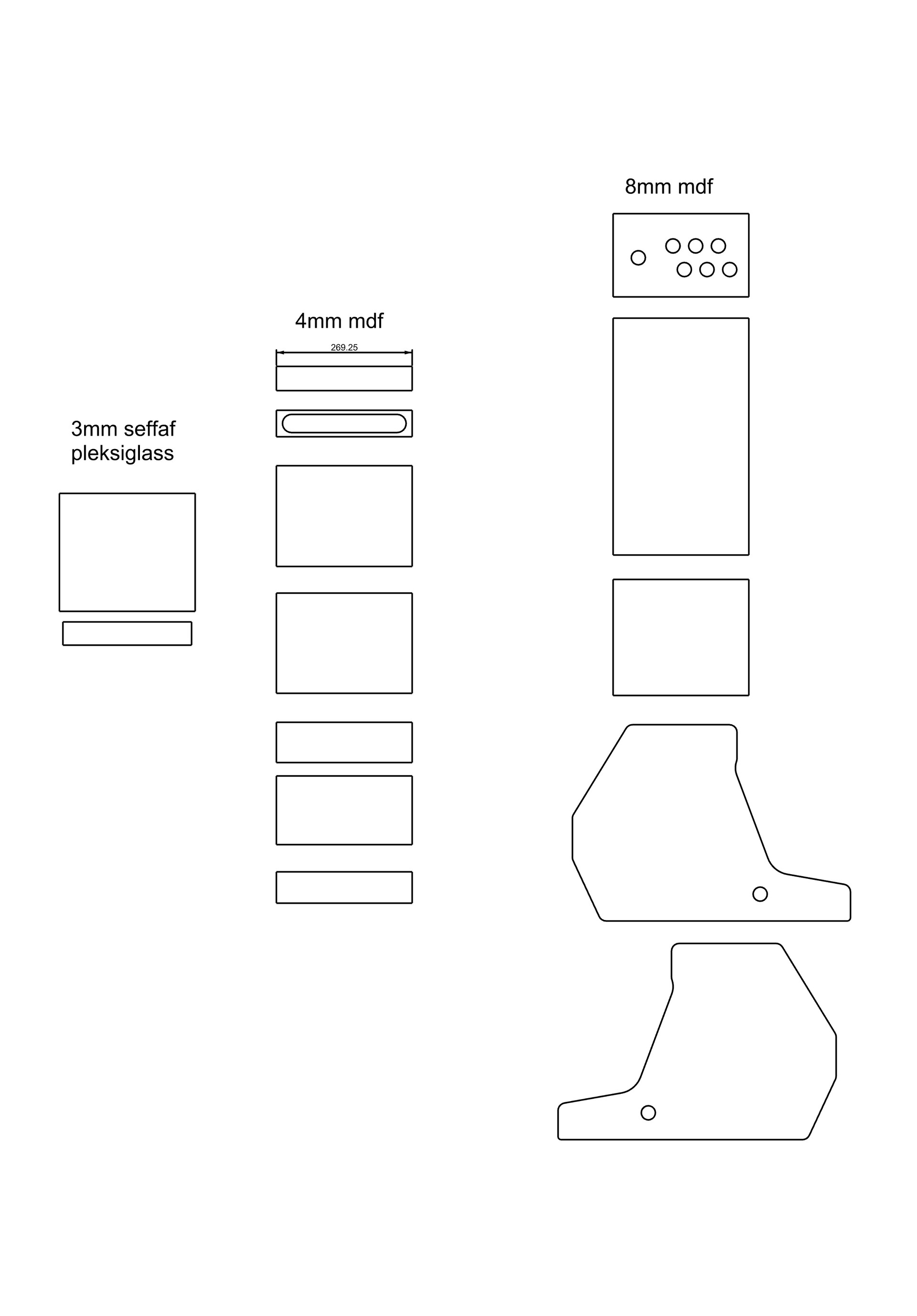
And I exported the DWG files for the panels and ordered a laser cut service from a local advertisement company.
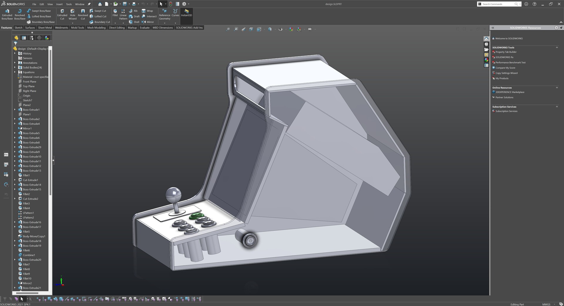
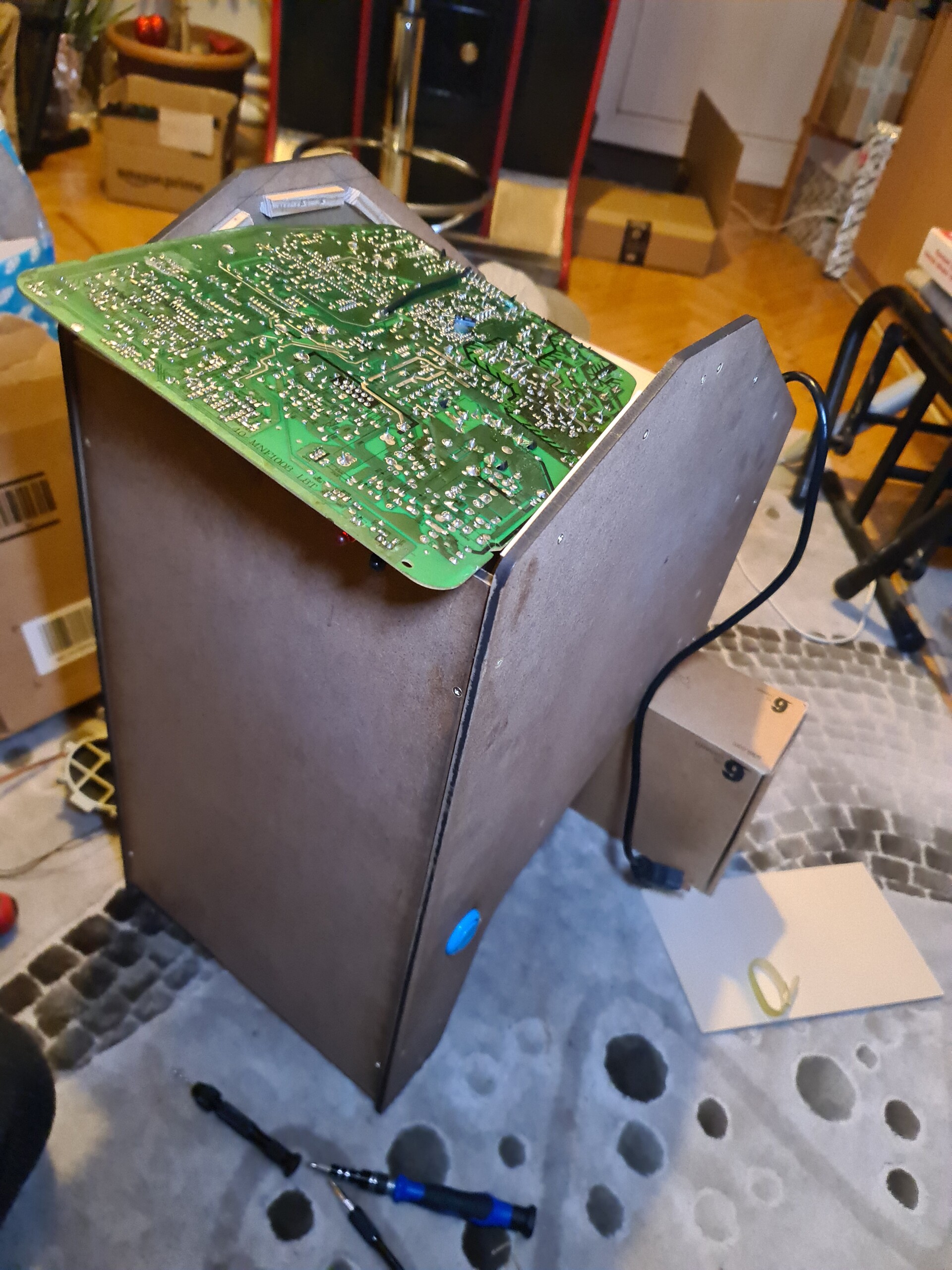
Once I received the cut panels, I realized that TV mainboard can't fit under the tube, so I placed the motherboard to the top on my 3d design (which was a unnecessary doubt since I see that it can fit, later).
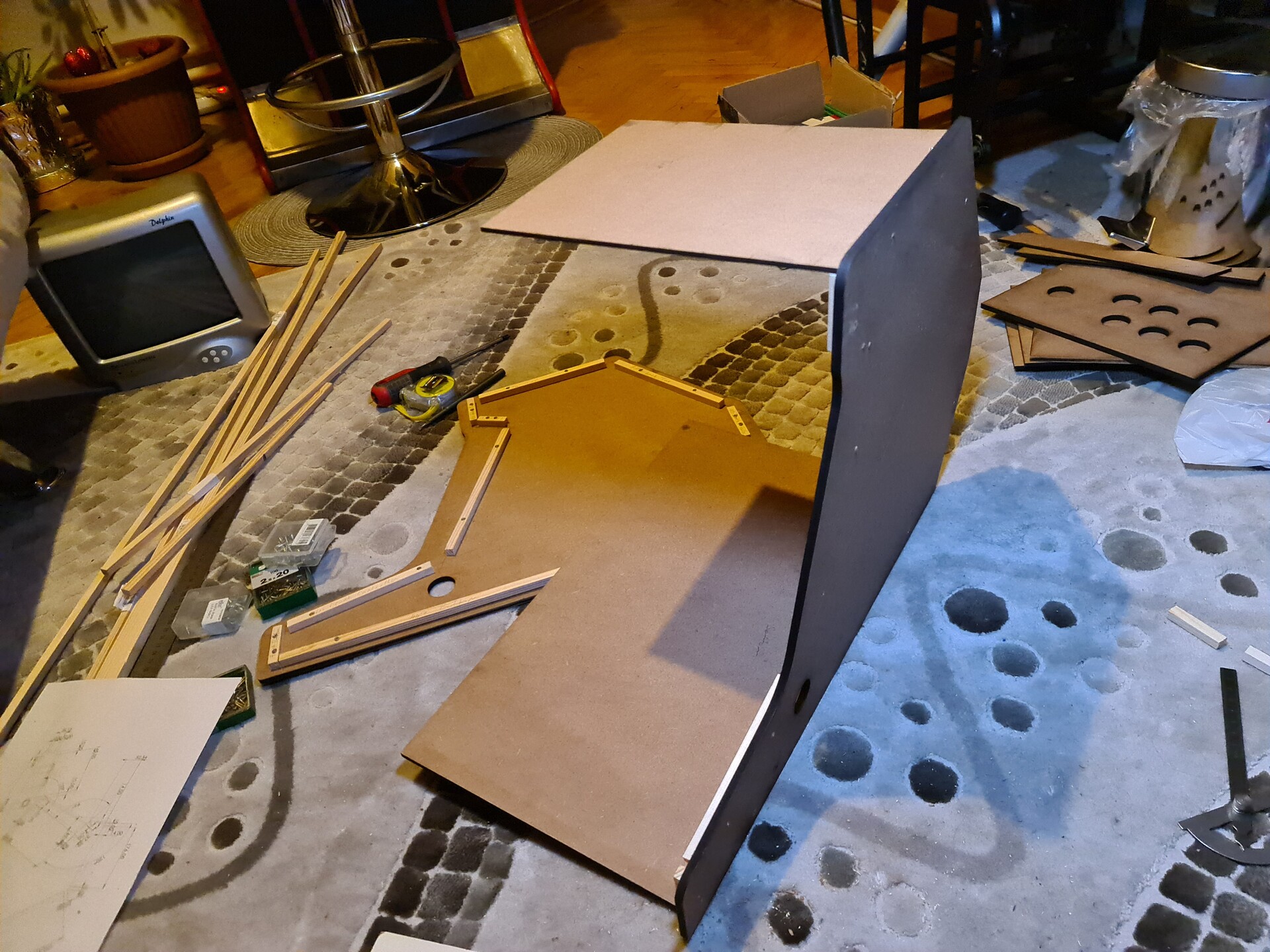
4. Constructing the Cabinet with Panels
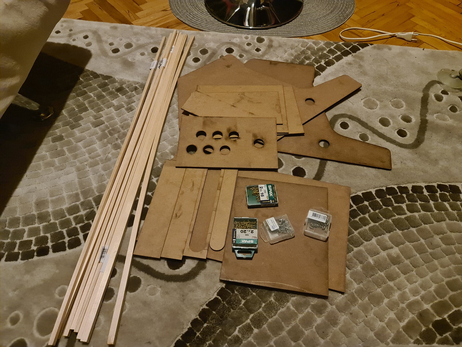
I bought some screws and laths to connect the boards. Laths are the best mounting aid for the MDF panels. I measured and cut the laths and placed them on the side panel first.
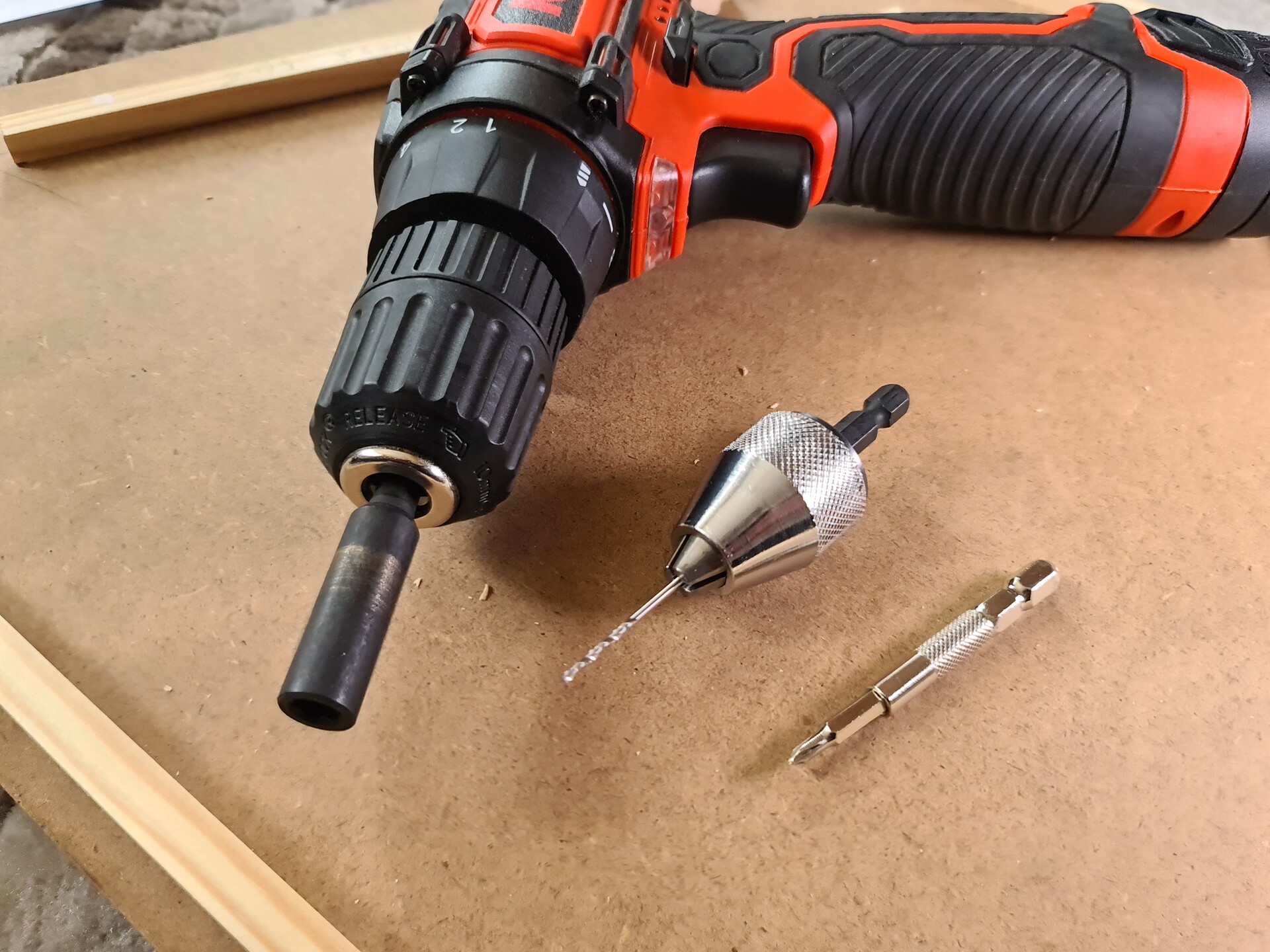
I used my hand drilling machine to drill holes and tighten the screws.
So after fixing the fisrt set of laths, I placed the panels and hoped that I didn't made a mistake on my quick design :)
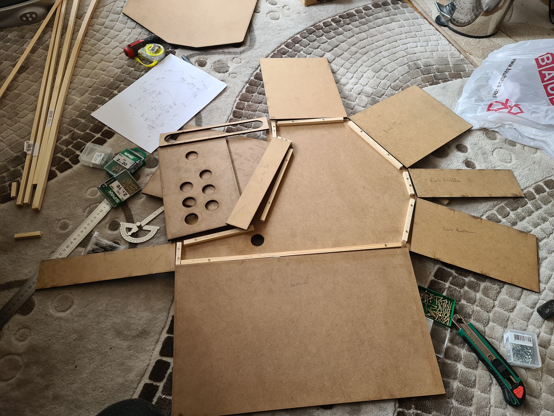
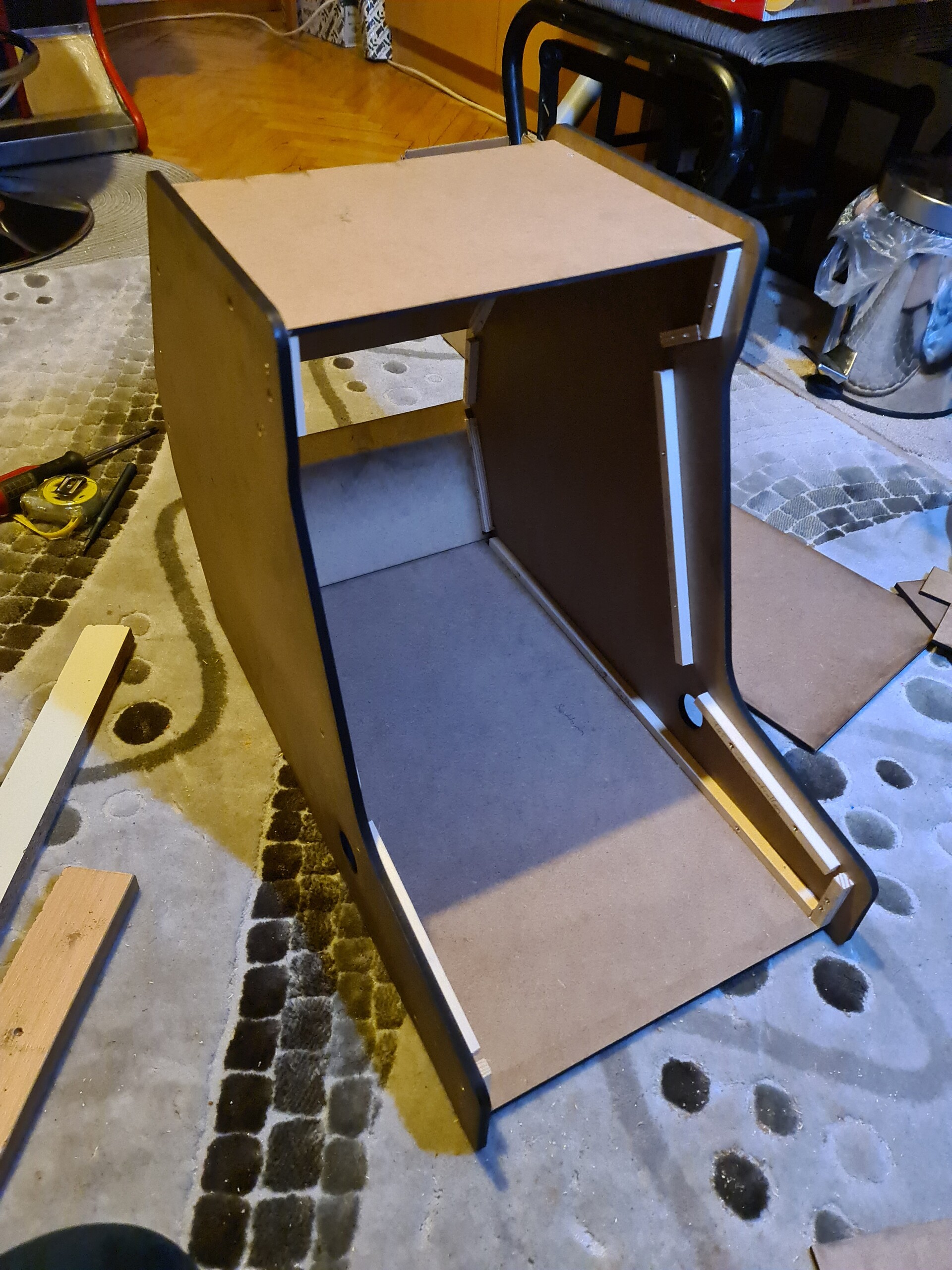
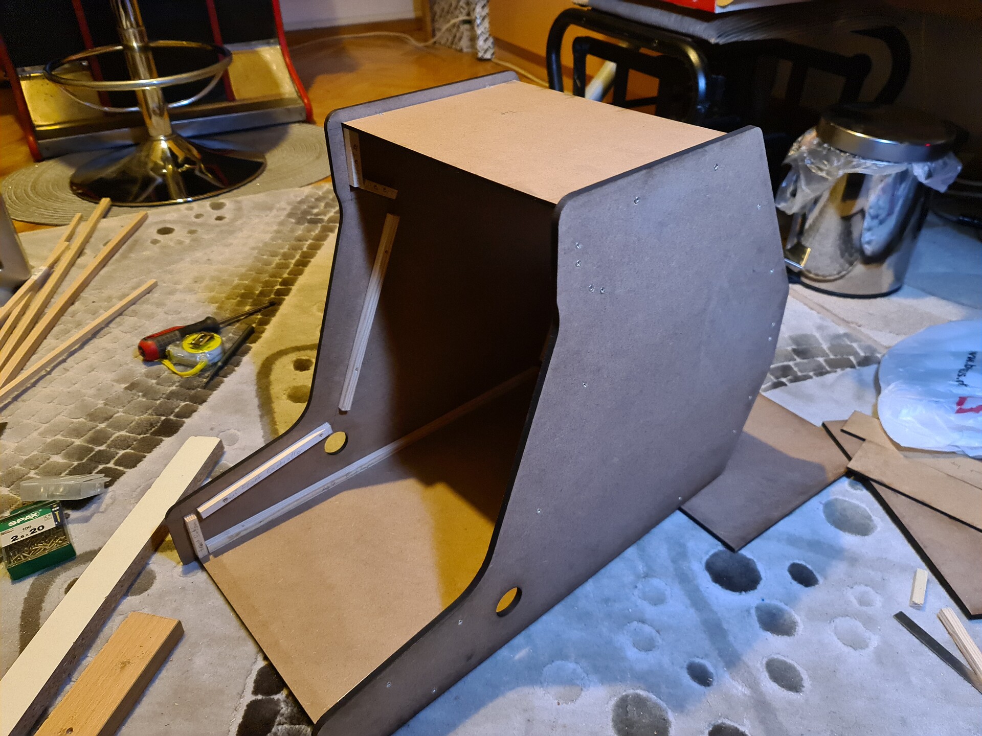
Since I needed to fix the laths on the both side panels, I needed to fix them on the exact opposite position. Quadrant is a useful too for matching the angles on both sides. I drew lines for the positions of the laths.

After fixing all the laths, I drilled and screwed the panels one by one.
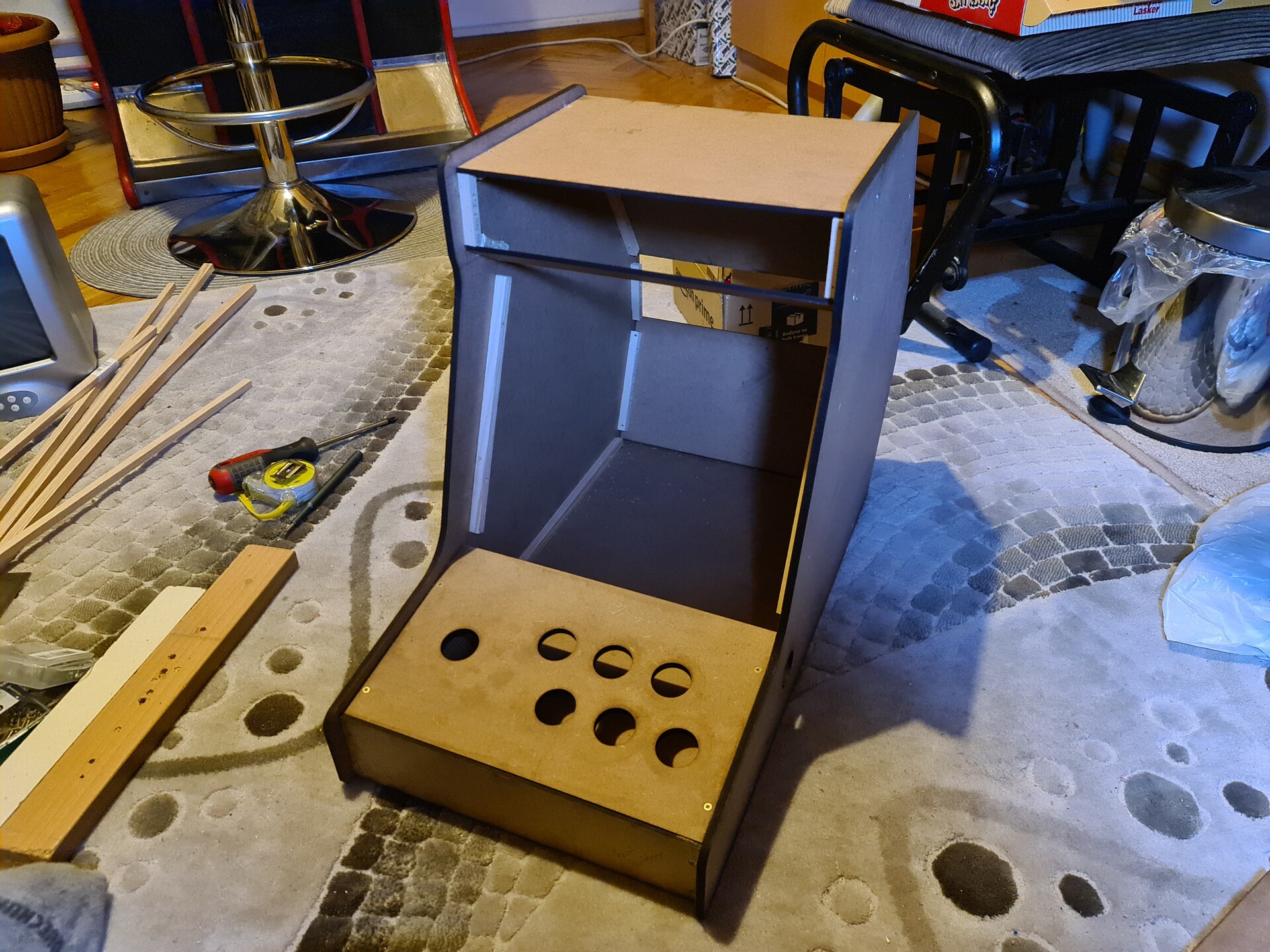
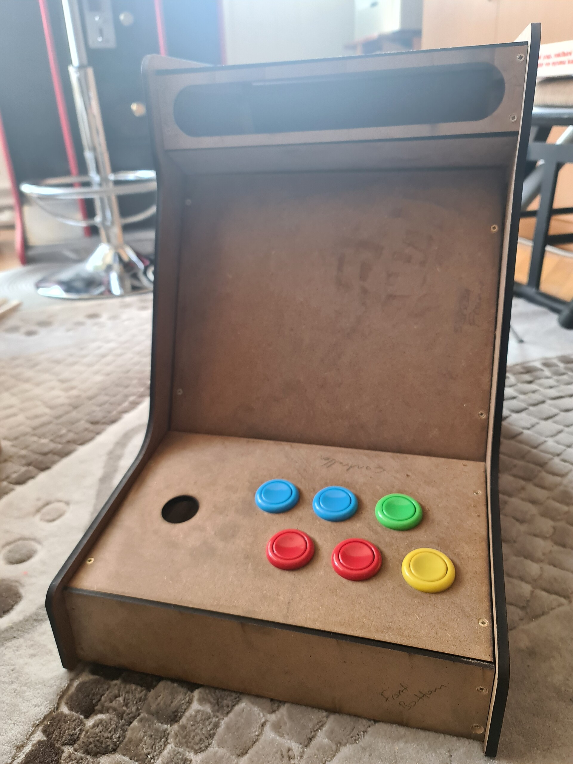
Since I couldn't be able to draw the hole for the tube hole, I needed to cut it by hand using a jigsaw. I made a terrible job but I was confident that I can cover the problematic gaps with sticker vinyl.
Finally I managed to fix the tube to the frame.
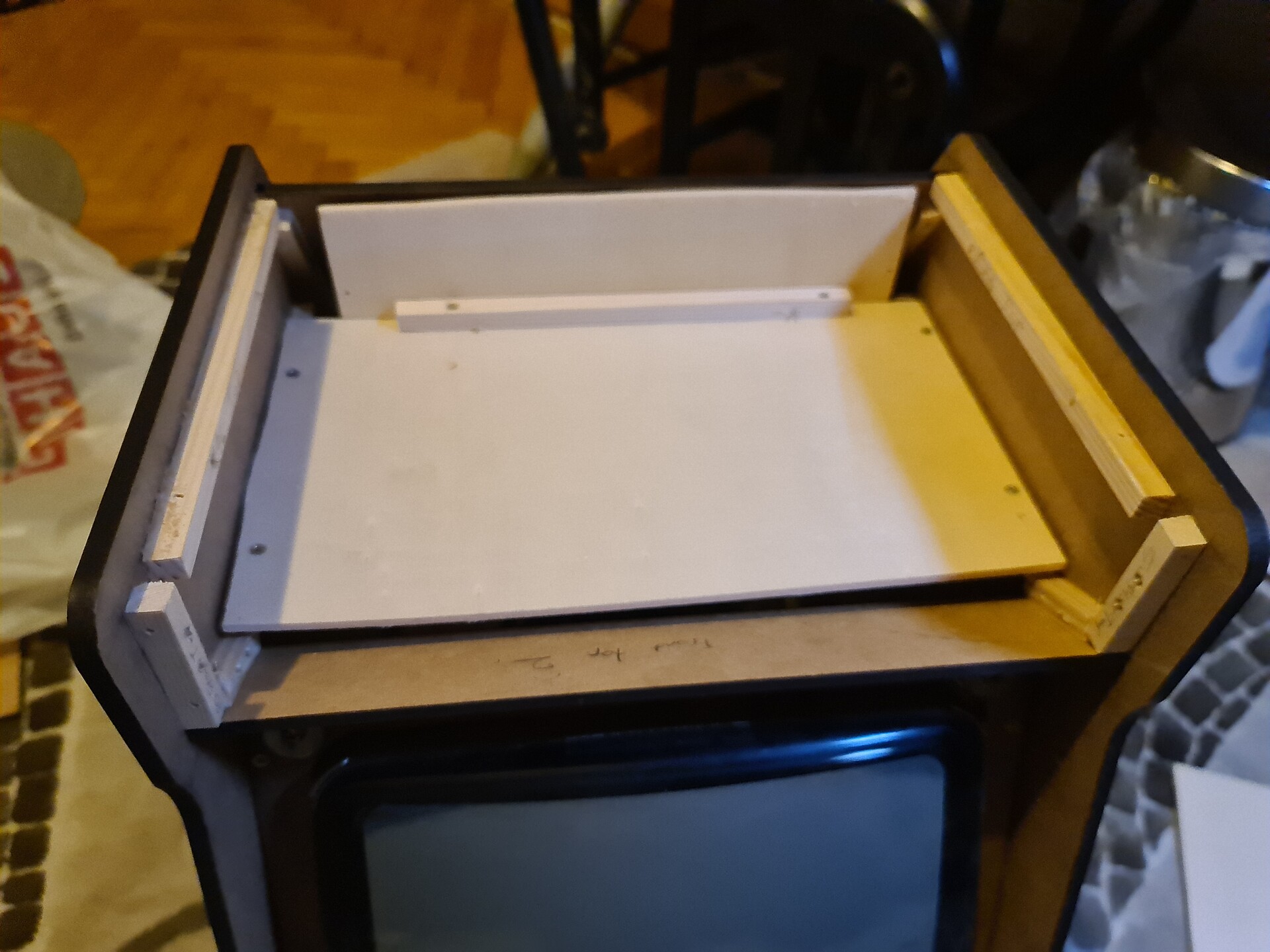
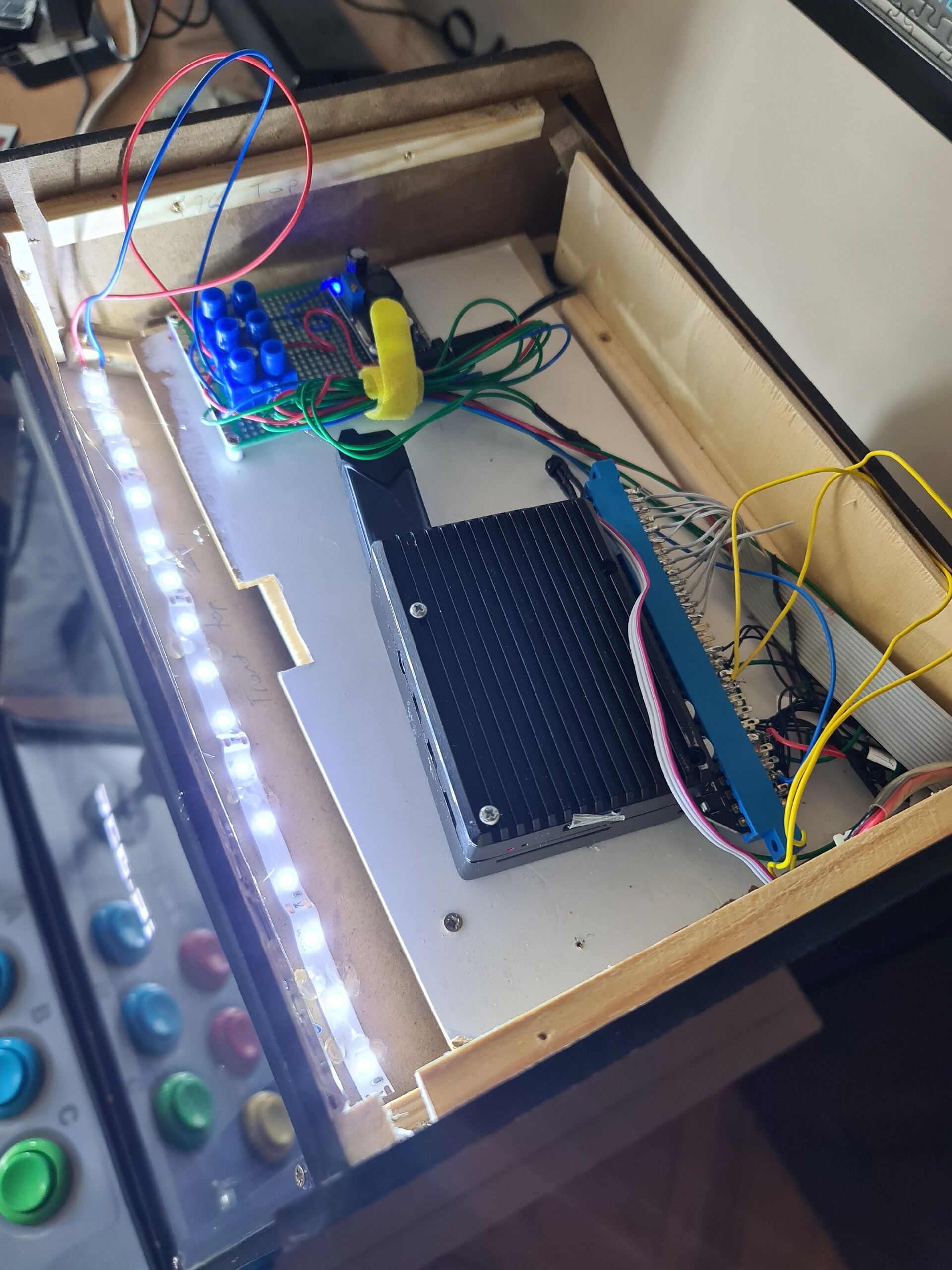
Next, I made a platform for to place the raspberry pi and jamma connector.
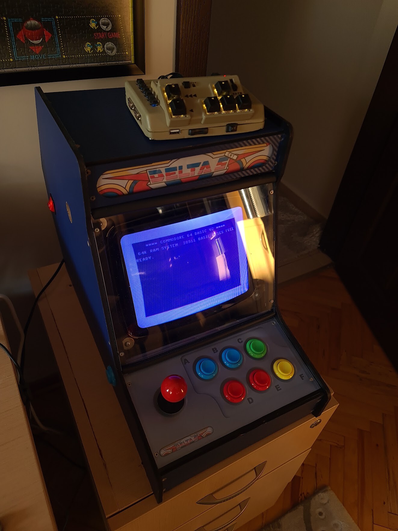
5. Electronic Touches and Finalization
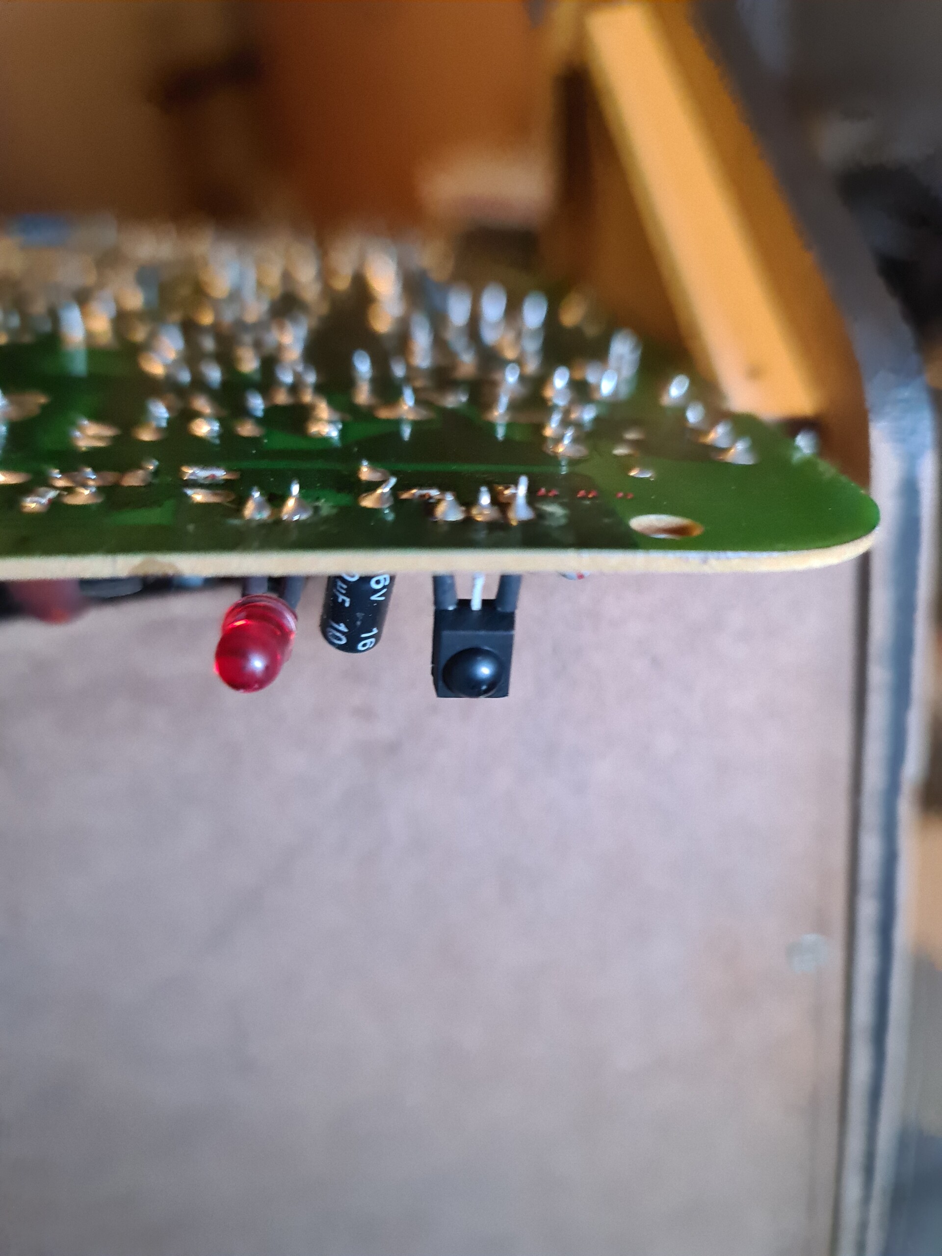
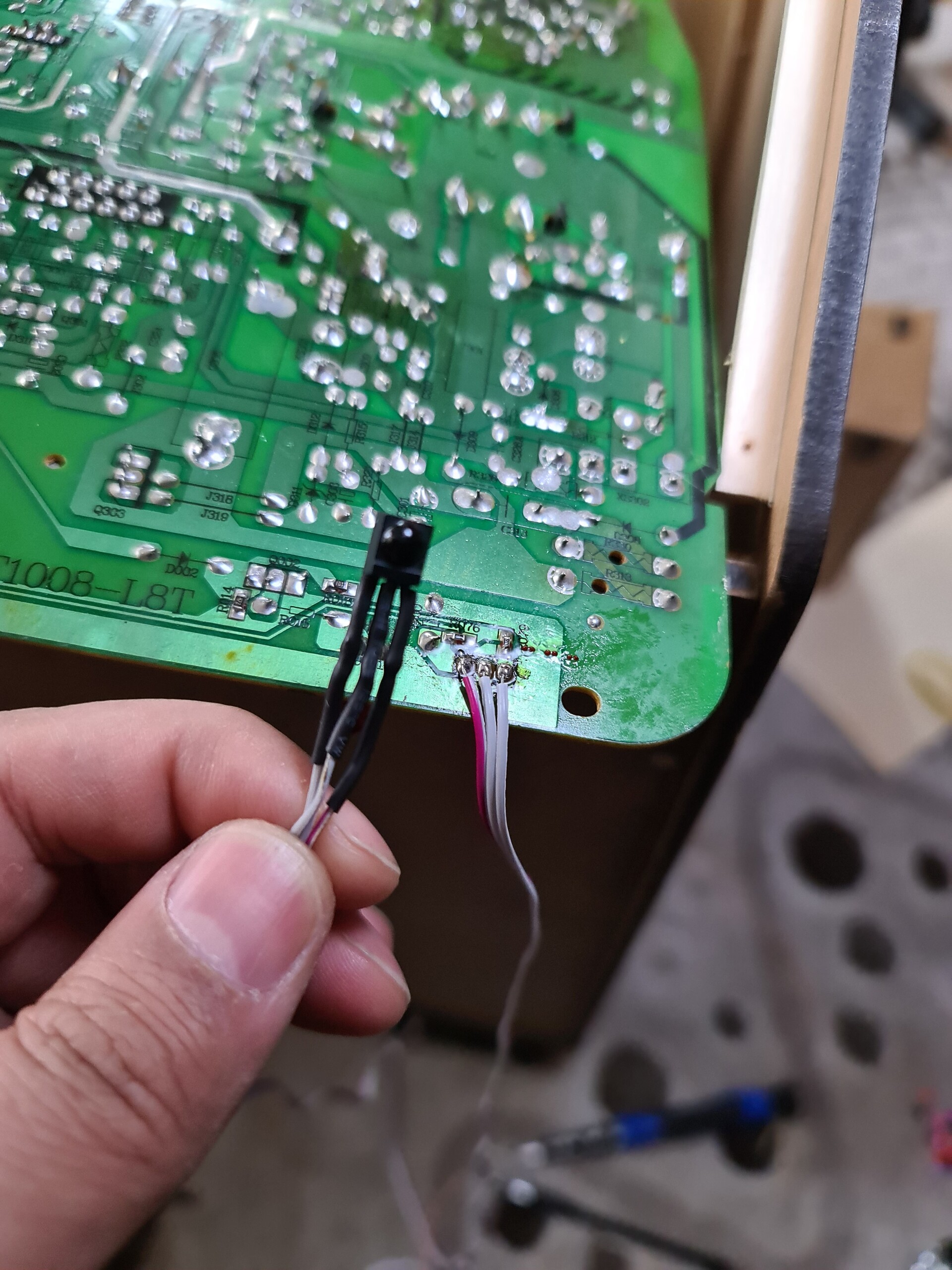
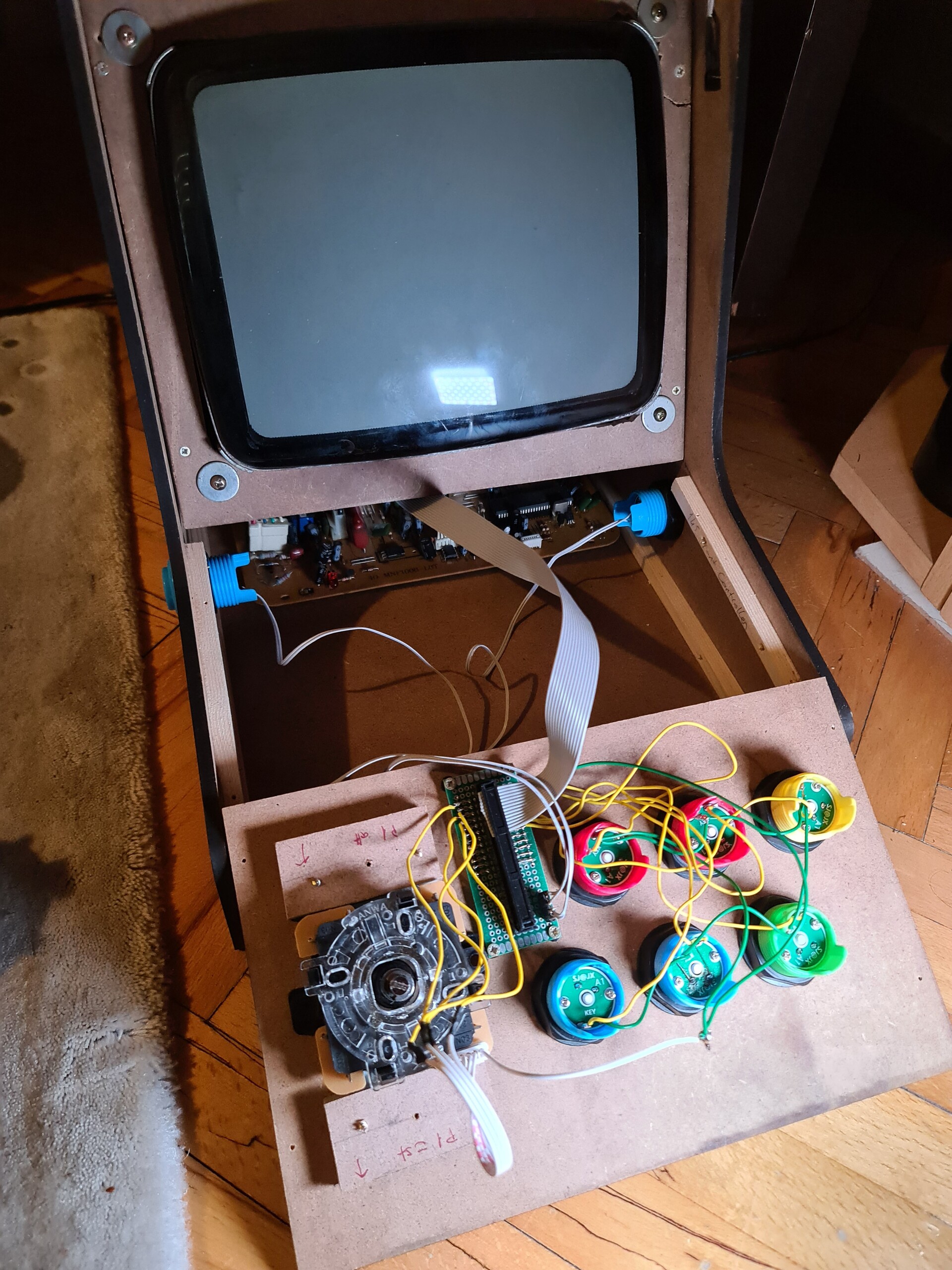
Since I'm using a TV, I need to user the remote control of the TV to adjust image etc. It's needed to place the IR sensor of the remote control, because the mainboard of the TV will be placed at the bottom back side of the cabinet. So I desoldered the sensor and soldered a cable to place the sensor at the top of the cabinet.
After moving the sensor, I soldered cables for the connector part. I used a 40 pin connector to detach the controller panel anyhtime in future for maintenance purposes.
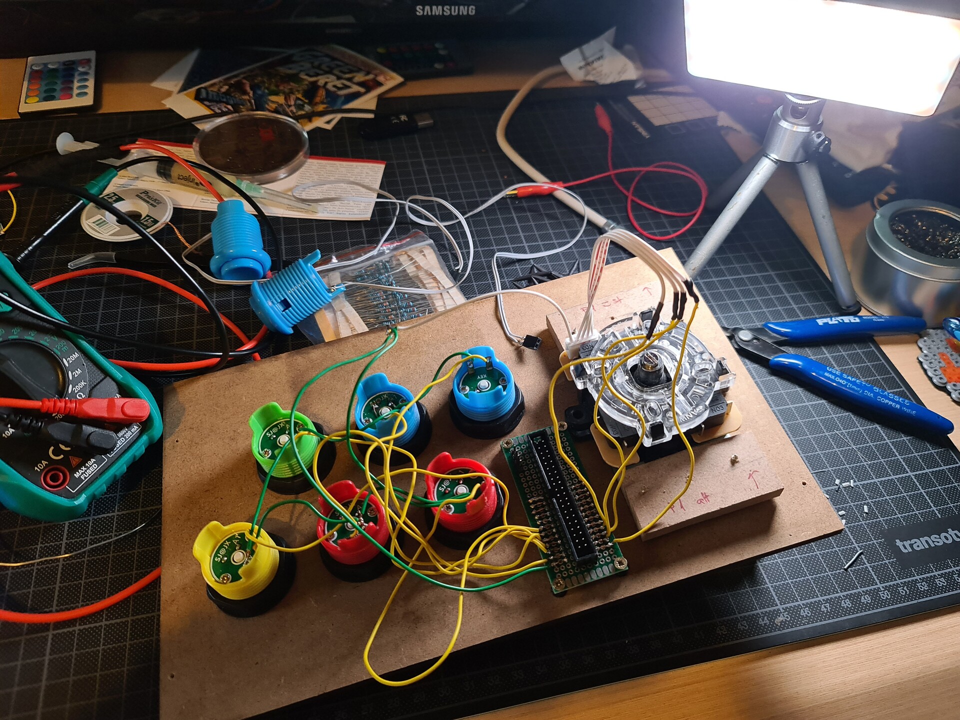
I used a DC voltage stepdown module for reducing 12V DC voltage to 5 volts. This way I can use both 12V and 5V DC for jamma to operate raspberry pi and the speaker amp circuit.

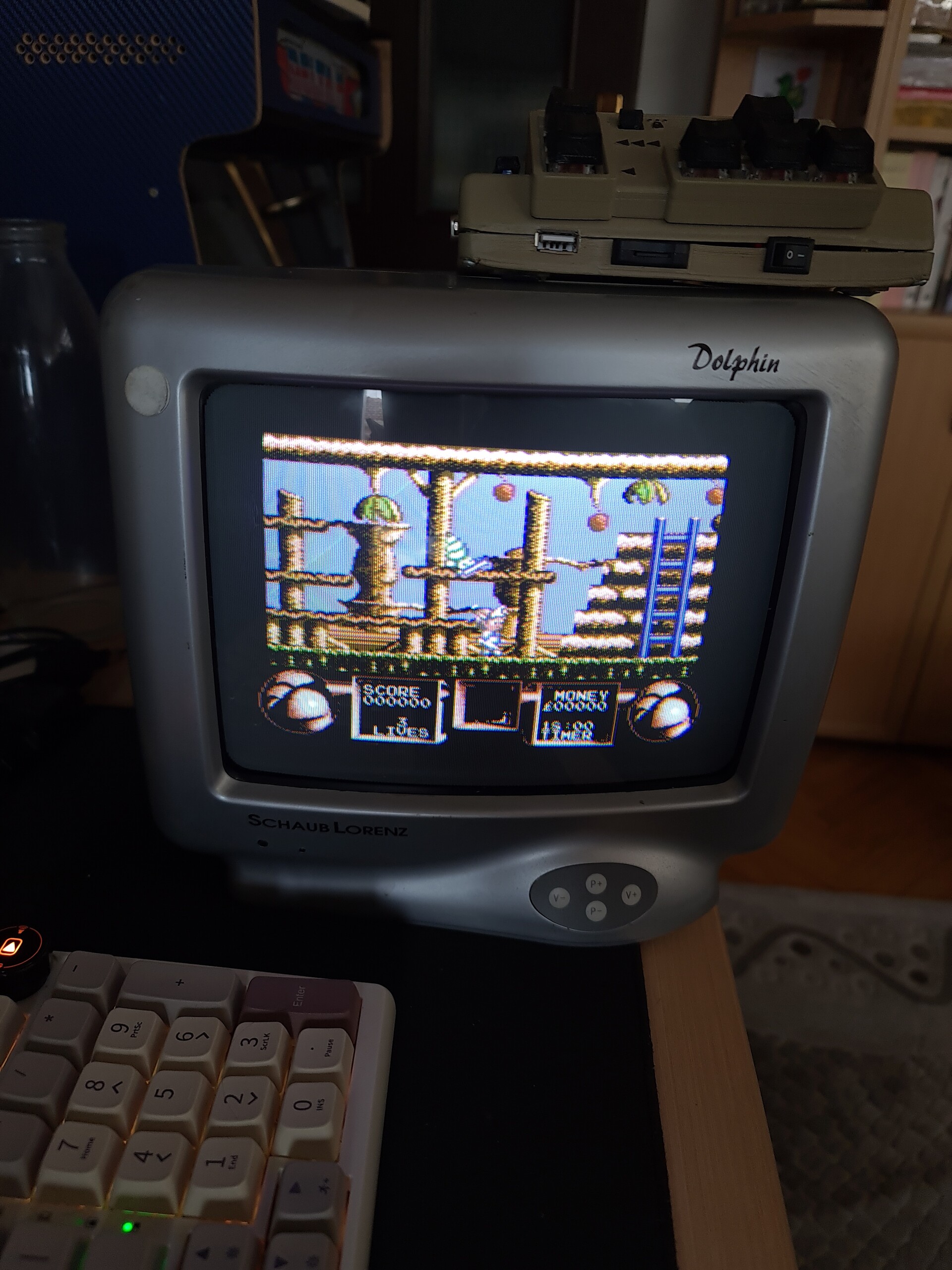
I use RGB-Pi Jamma circuit (https://www.rgb-pi.com/) for emulating games. RGB-Pi is the perfect device with its own software which allows me to play the games at their original refresh rates. It works great with multisync CRT screen so this way TV shows the smooth scroll gaming on specific refresh rates. Classic arcade emulators run at fixed 60hz / 60fps. This way games that designed less than 60hz runs faster than their original way or you get screen tearing, frame skipping or other issues on emulation.
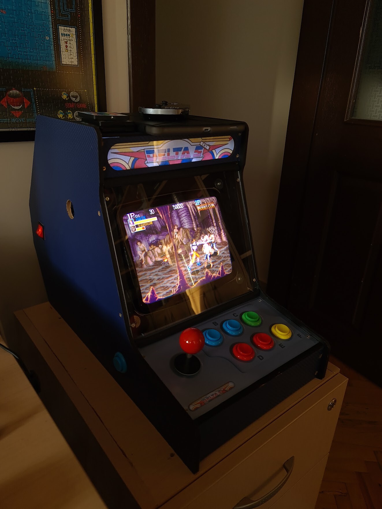
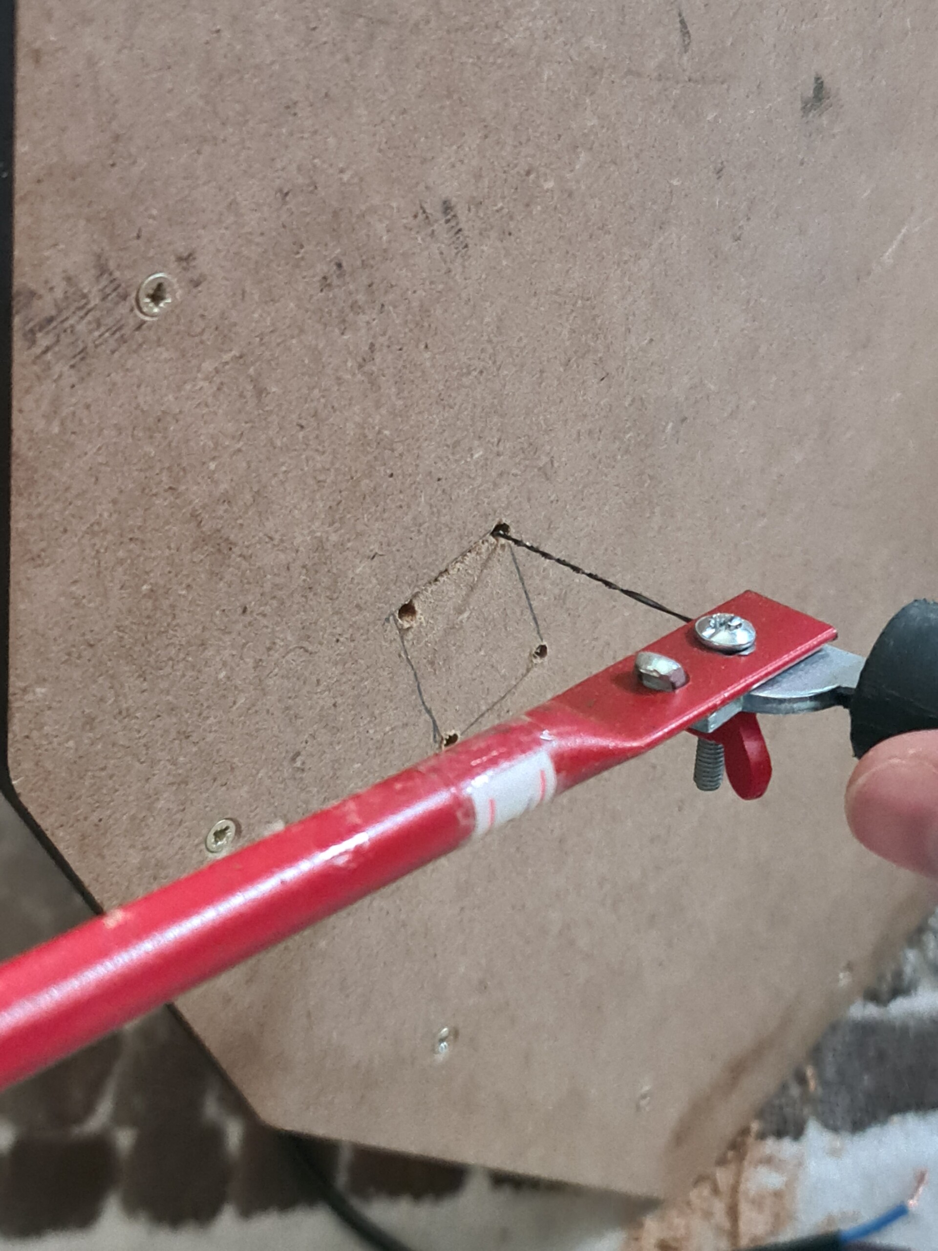
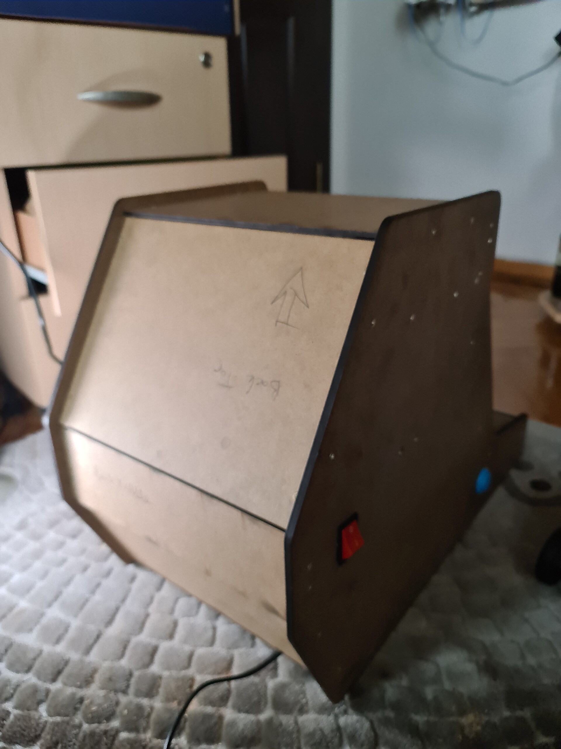
I placed the power switch to the left side of the cabinet by cutting a hole for it. I connected the 220 AC input the that switch and distributed that voltage to a 12v DC adapter and the TV itself.
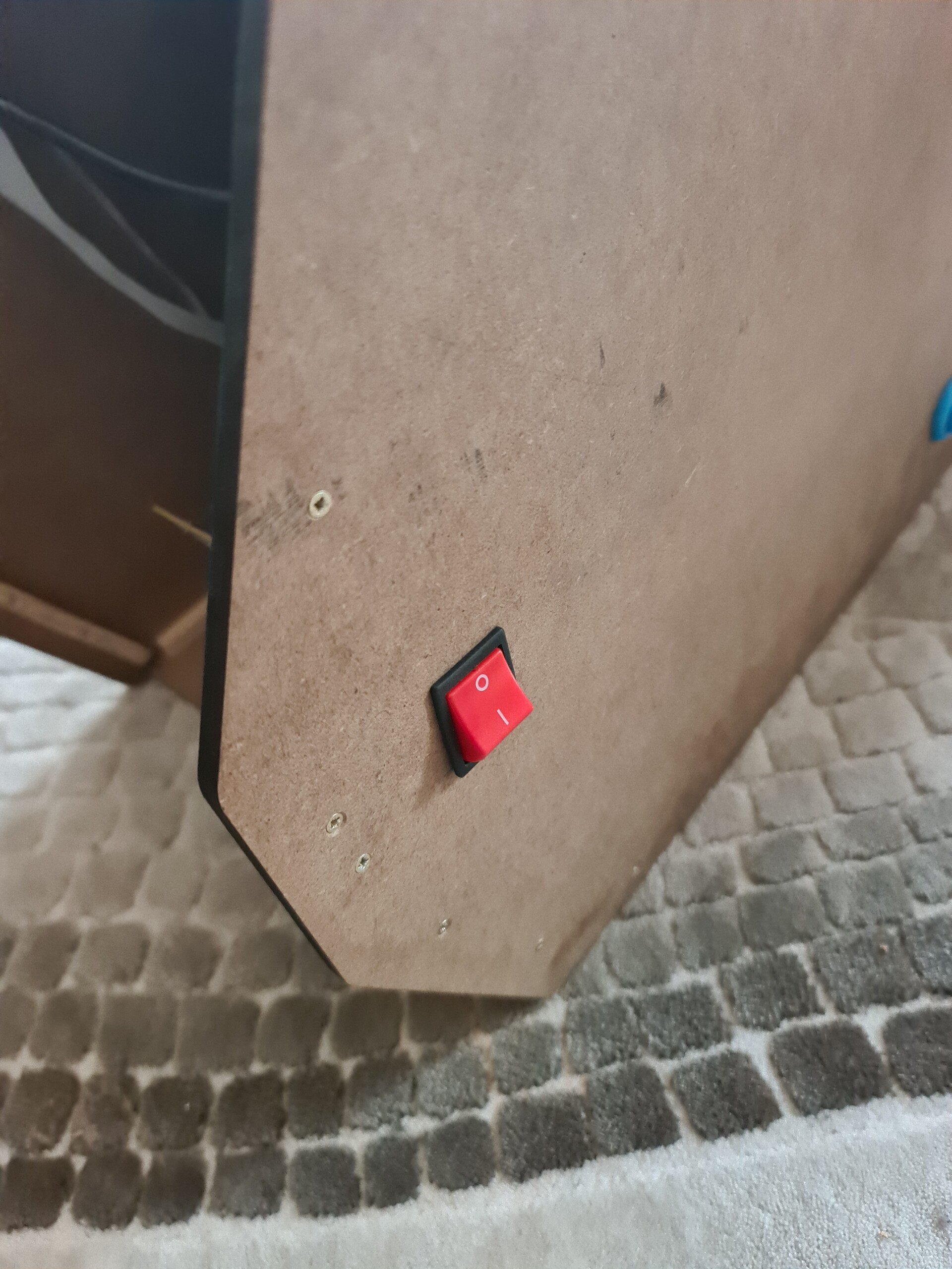
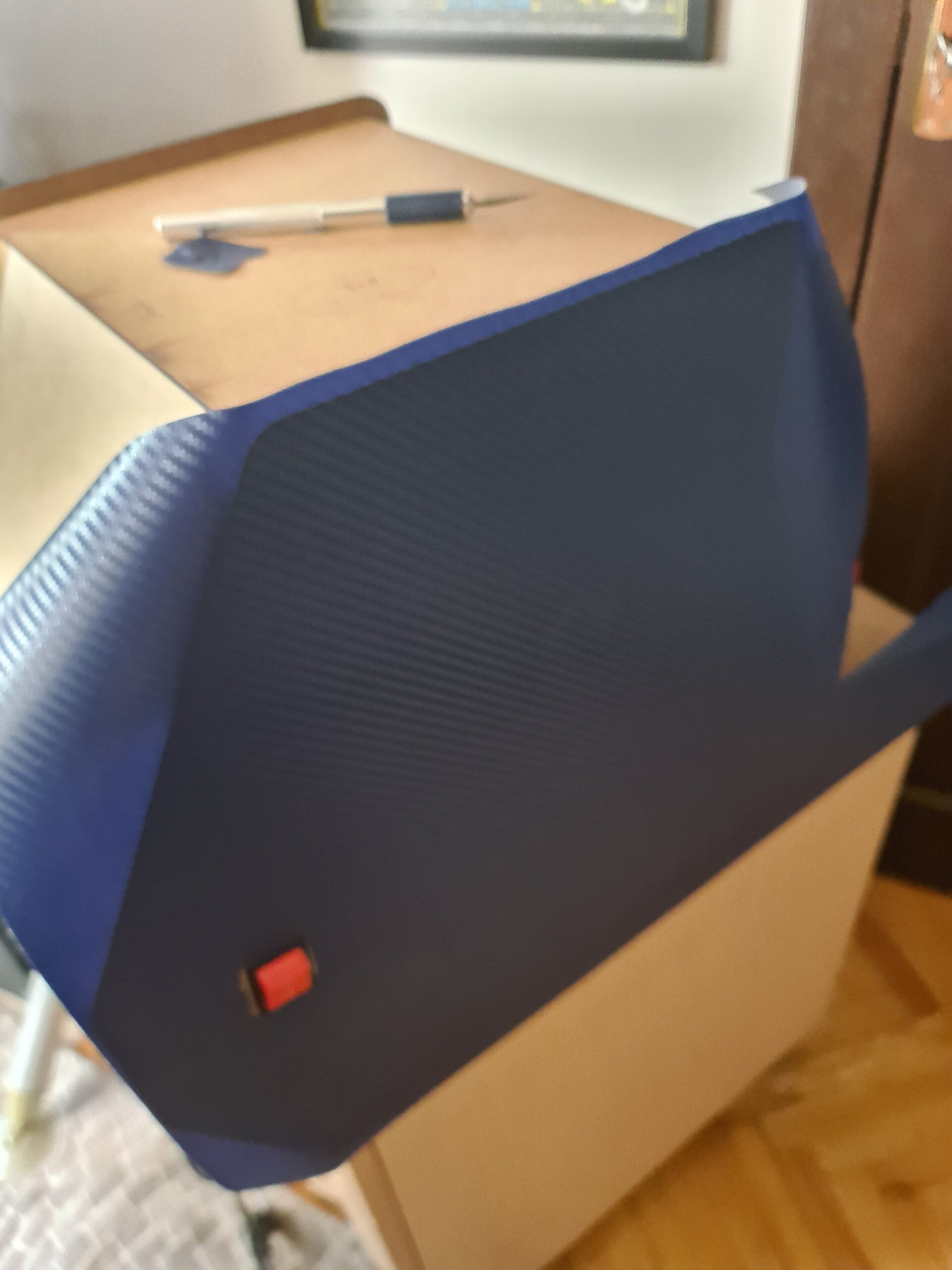
Works fine! So I closed the back panels and moved on with the covering the panels with vinyl folio.
I got some spare sticker folio from the last project so I applied it to the side and front panels.
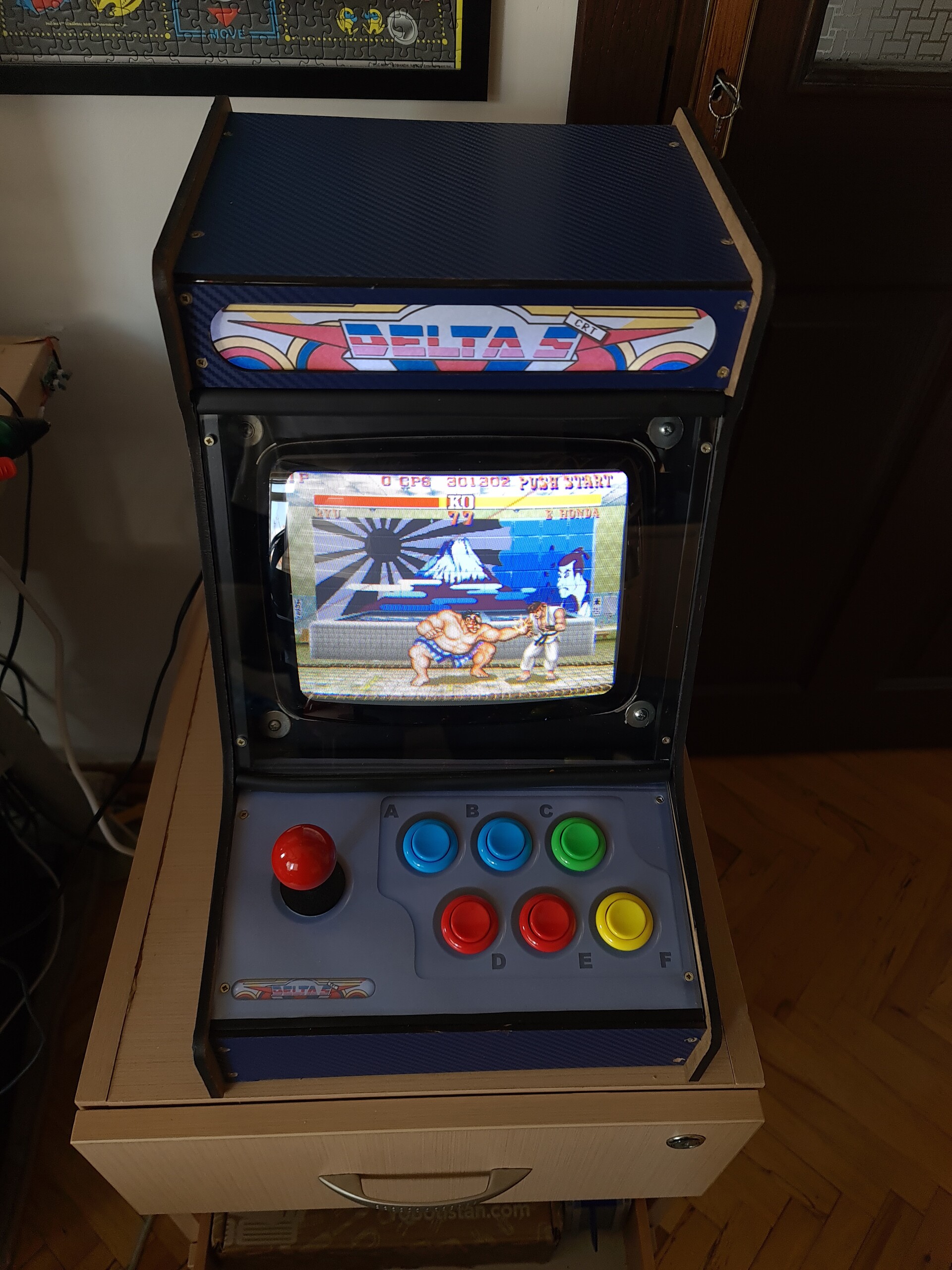
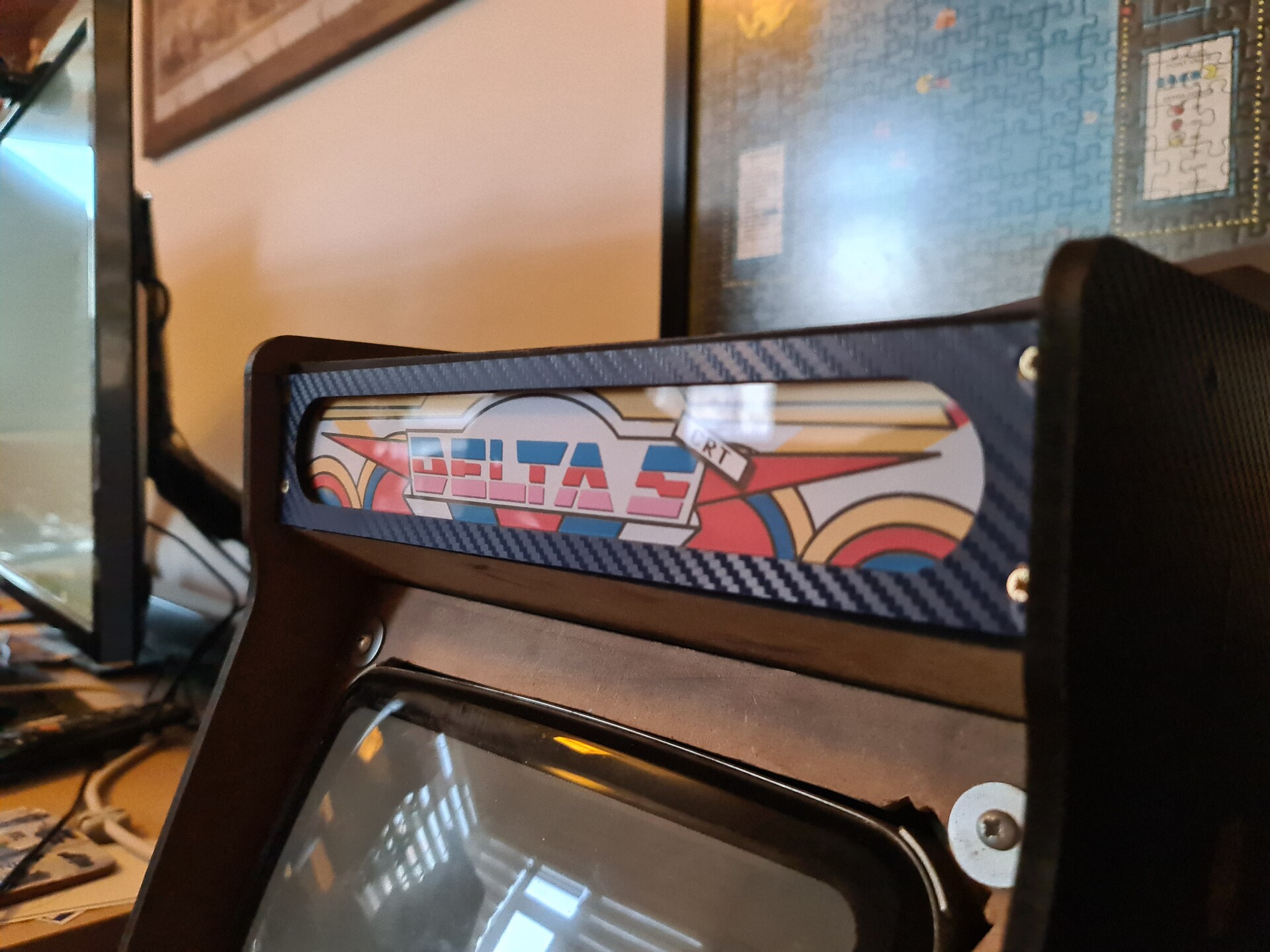
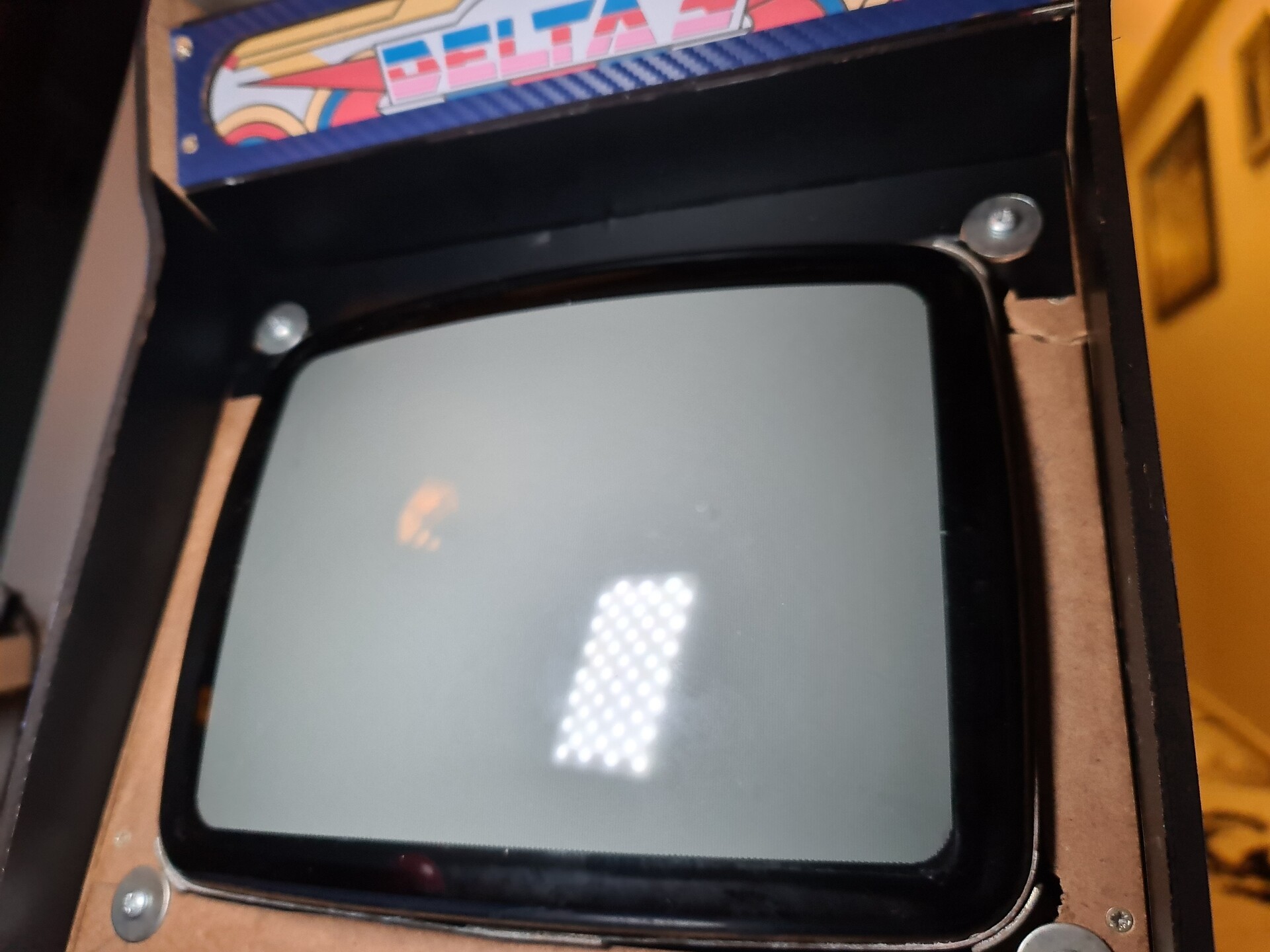
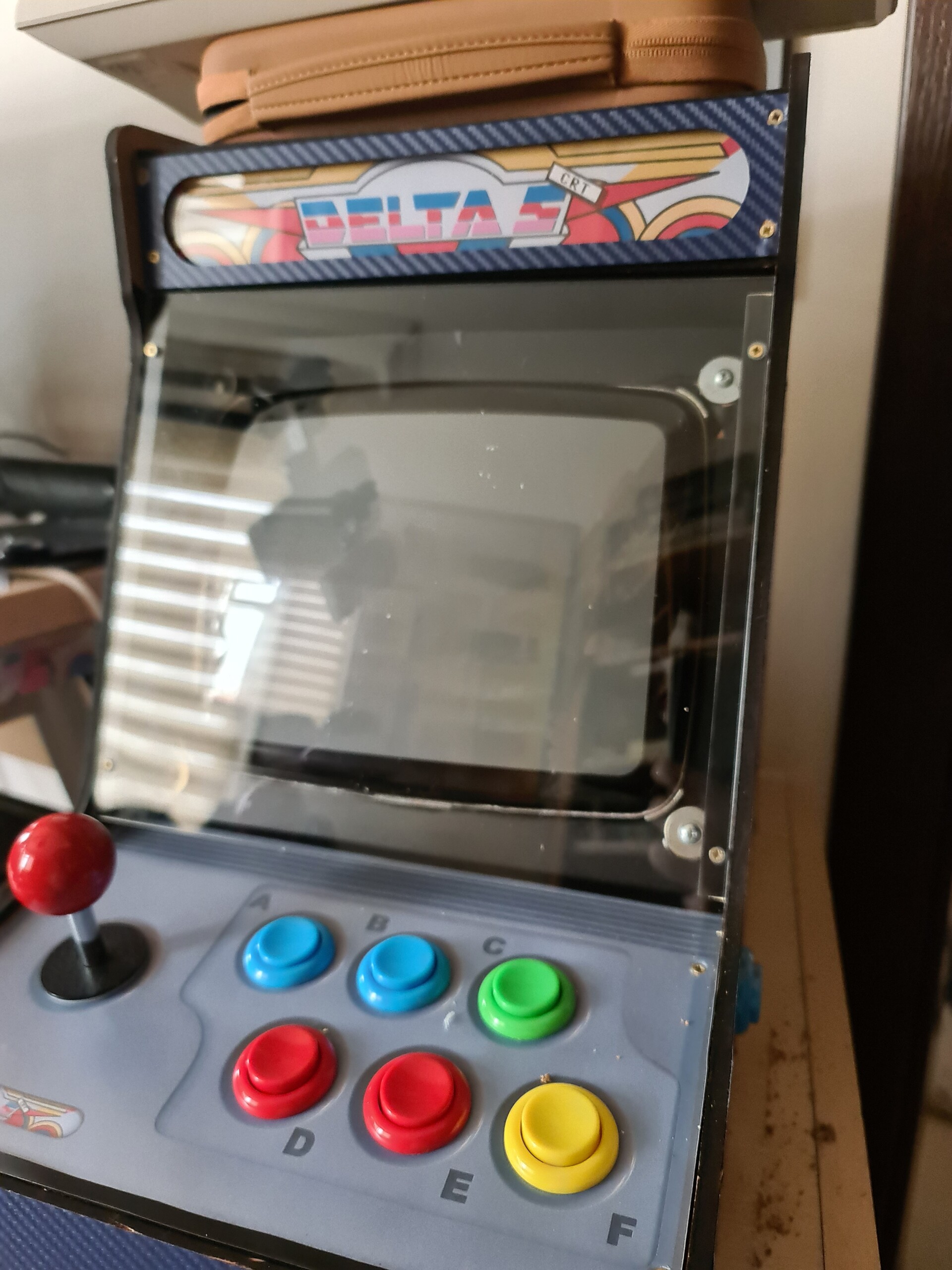
I used the previous design that I made for the LCD cabinet and put a CRT label to the top. Printed and applied to the plexiglass I have for the marquee area.

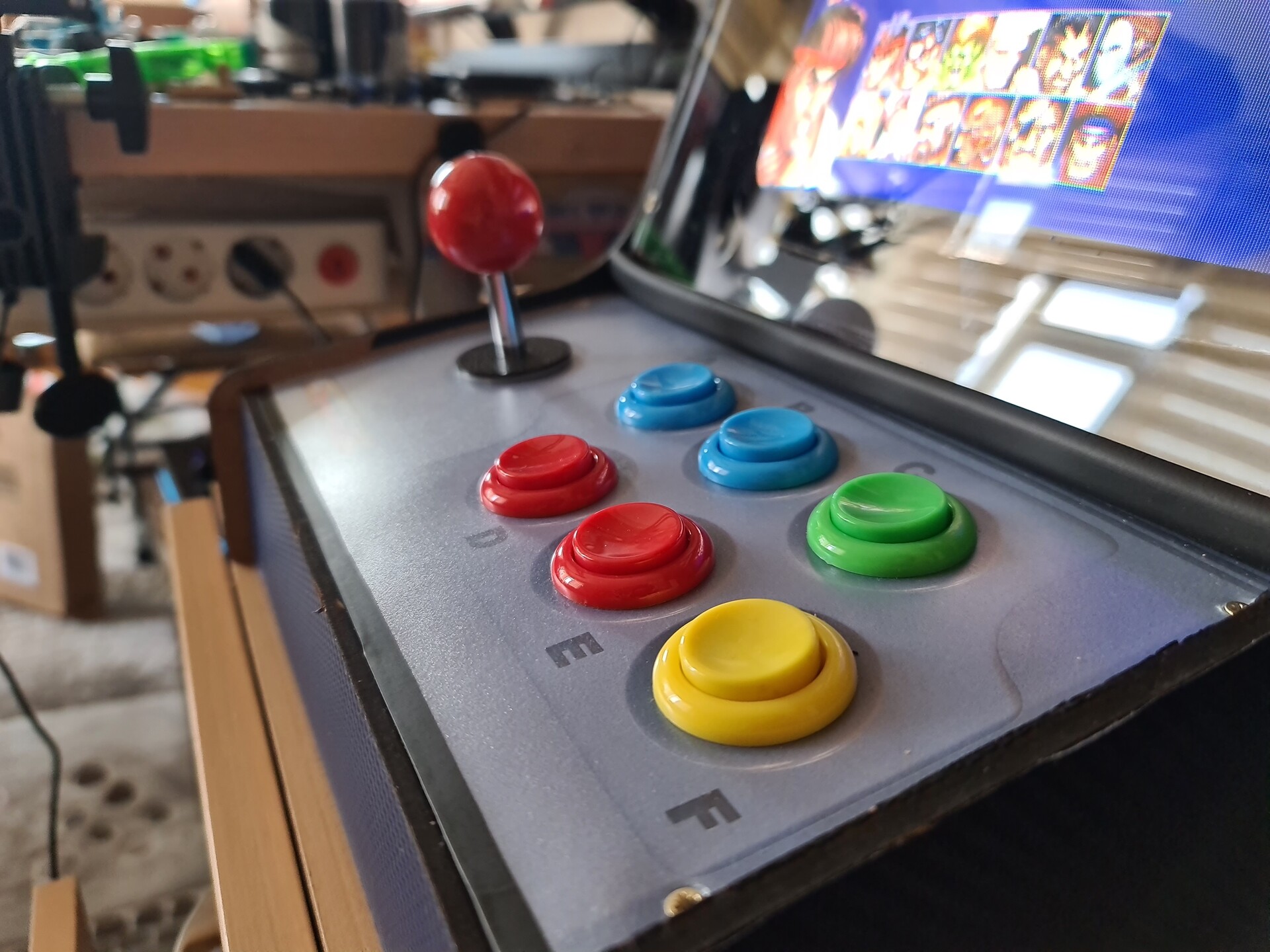
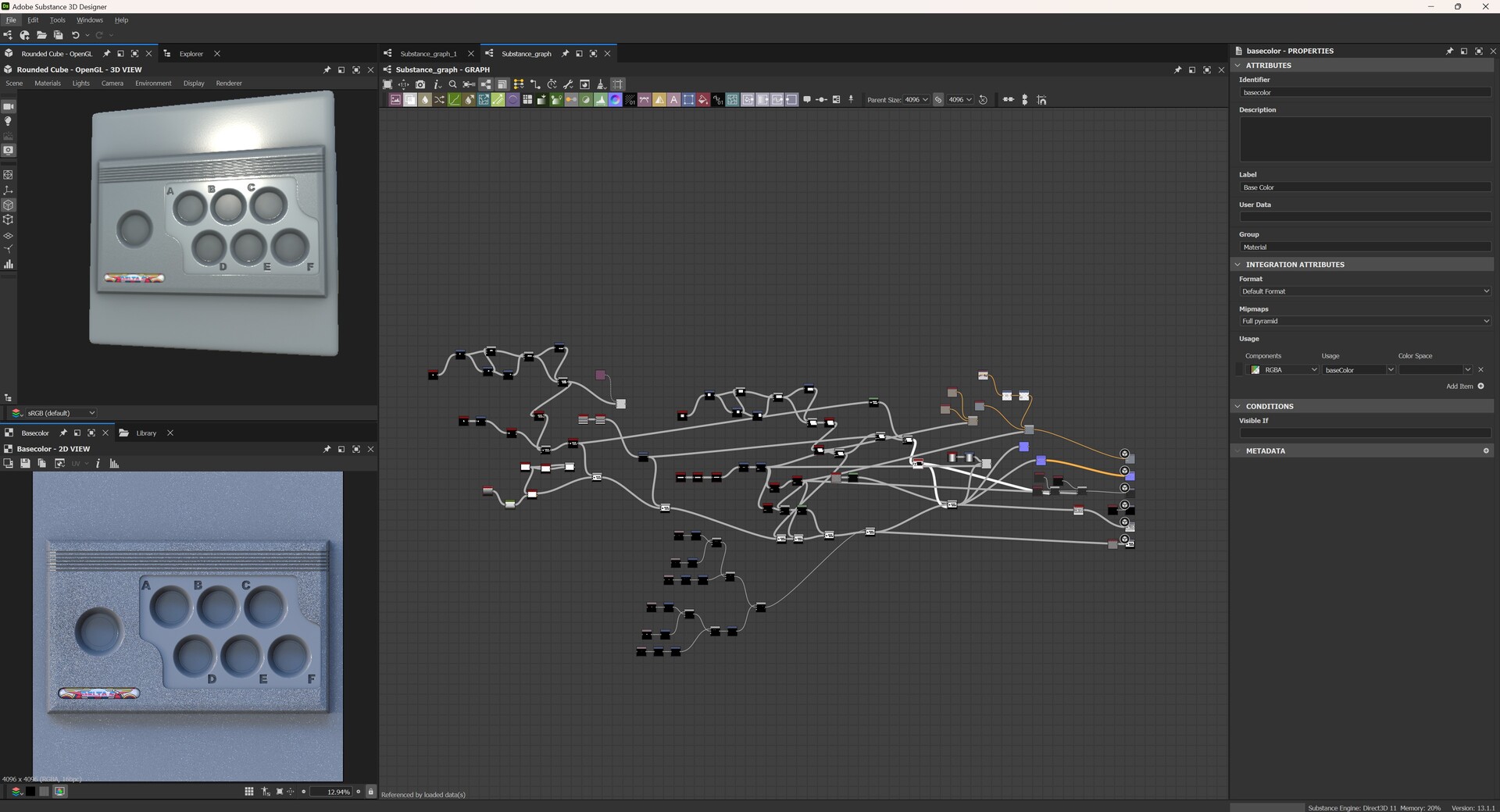
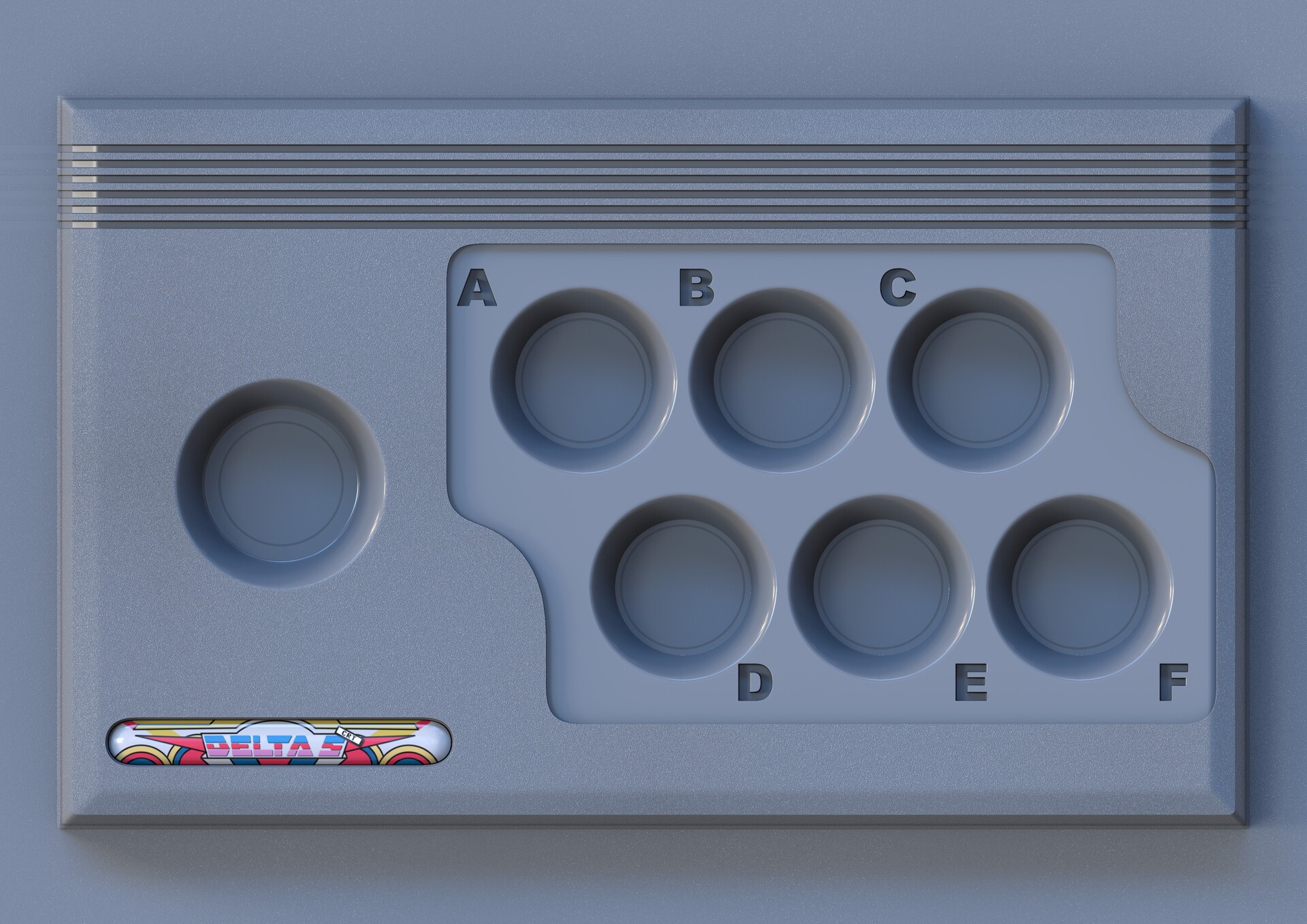
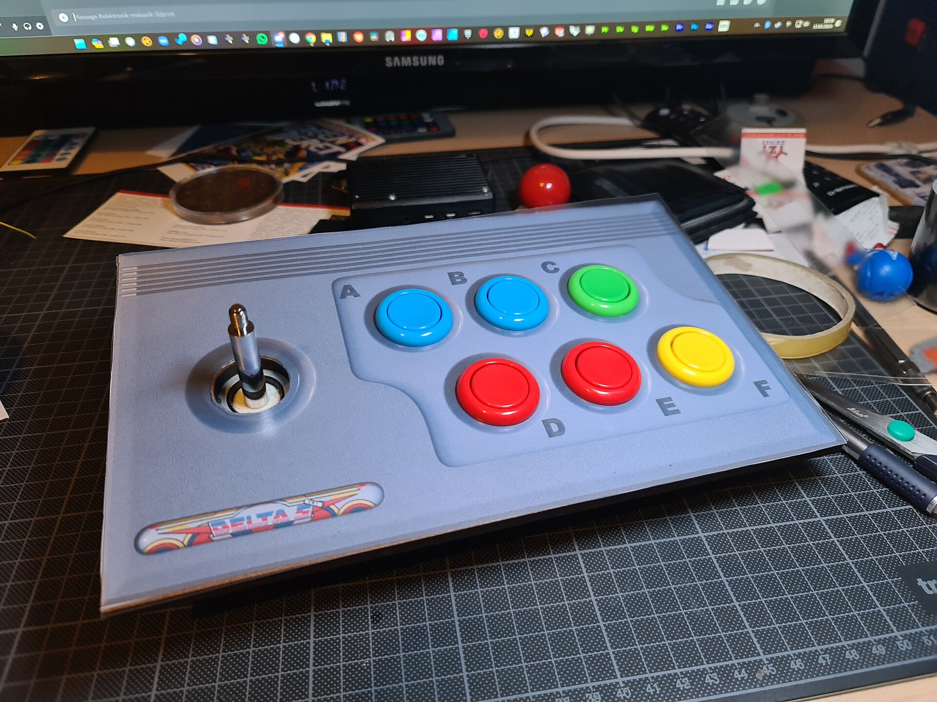
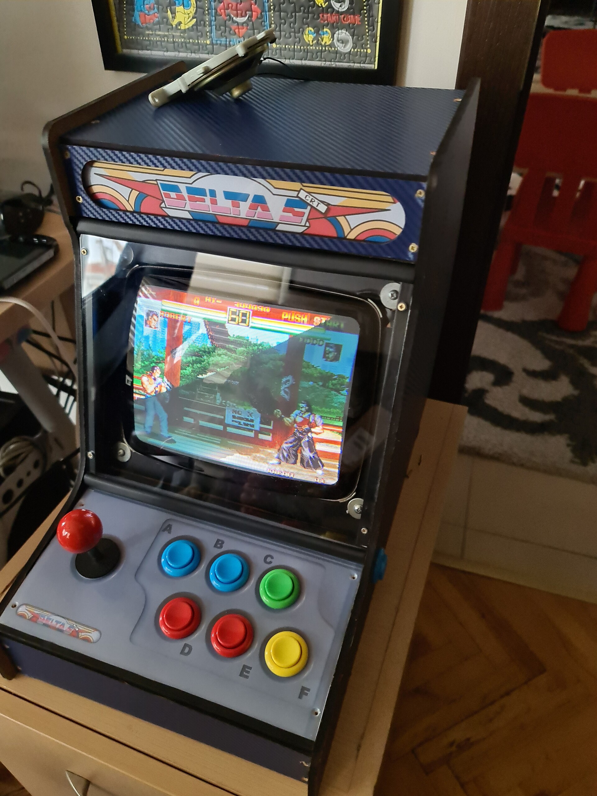
For the controller area, I used Substance Designer to make a procedural panel design and applied a shading for it with PBR render node within the software.

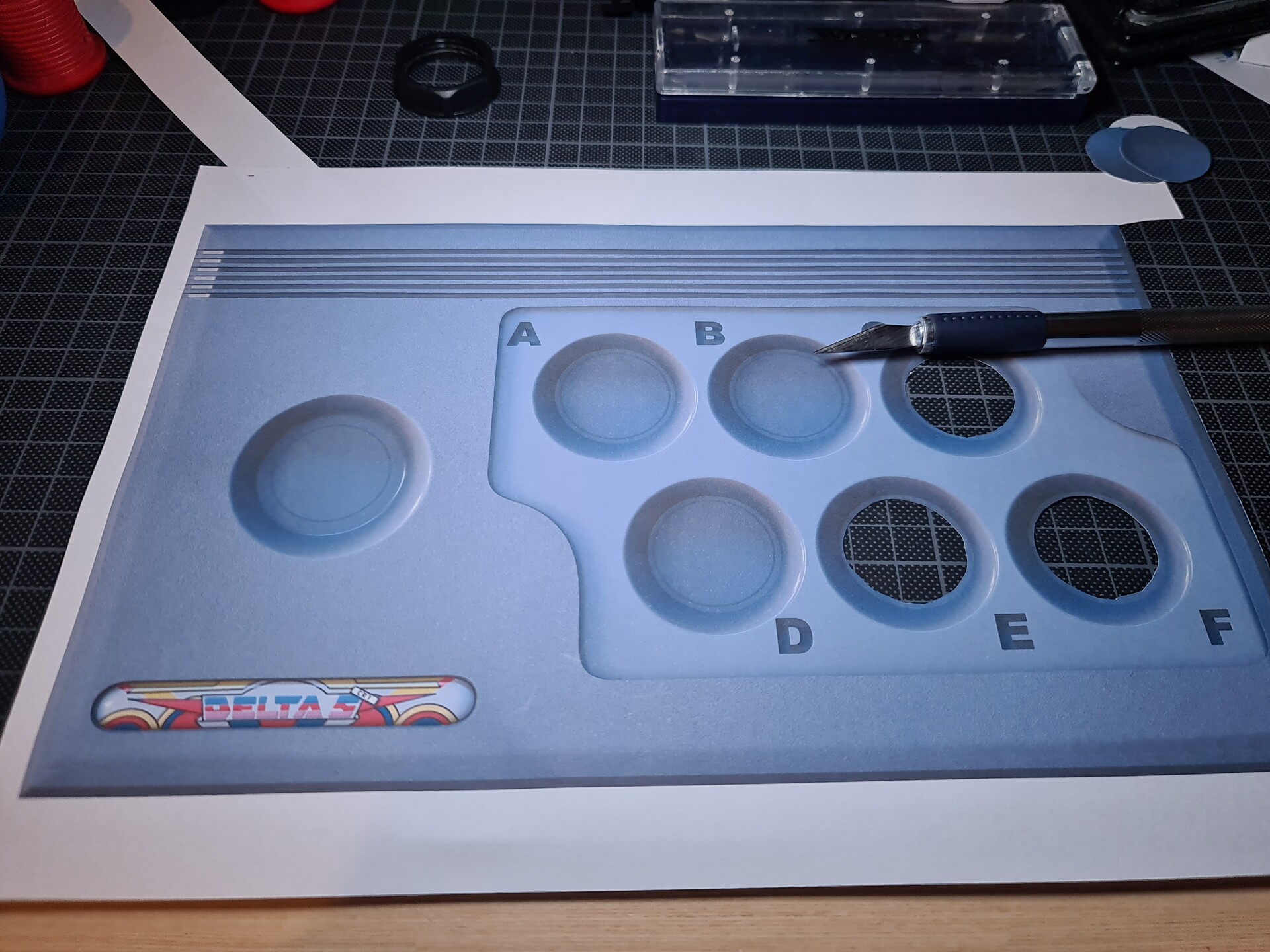
I fixed the plexiglass to the marquee window with hot glue. And then I used double sided tape to fix the printed out paper over it.

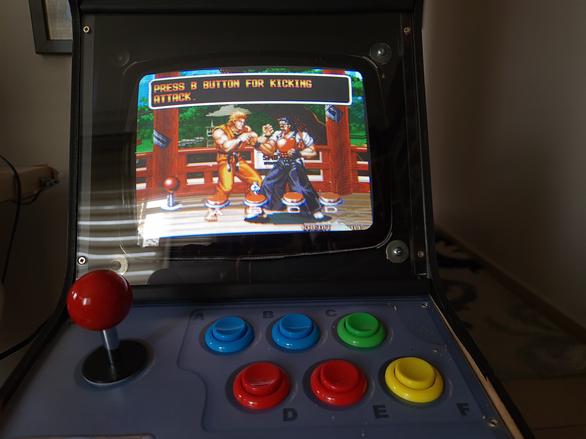
I cut the holes with the knife on the controller print-out. I cut the same holes over the PVC plate so the paper won't be affected by the hand sweat or dirt in time of usage.
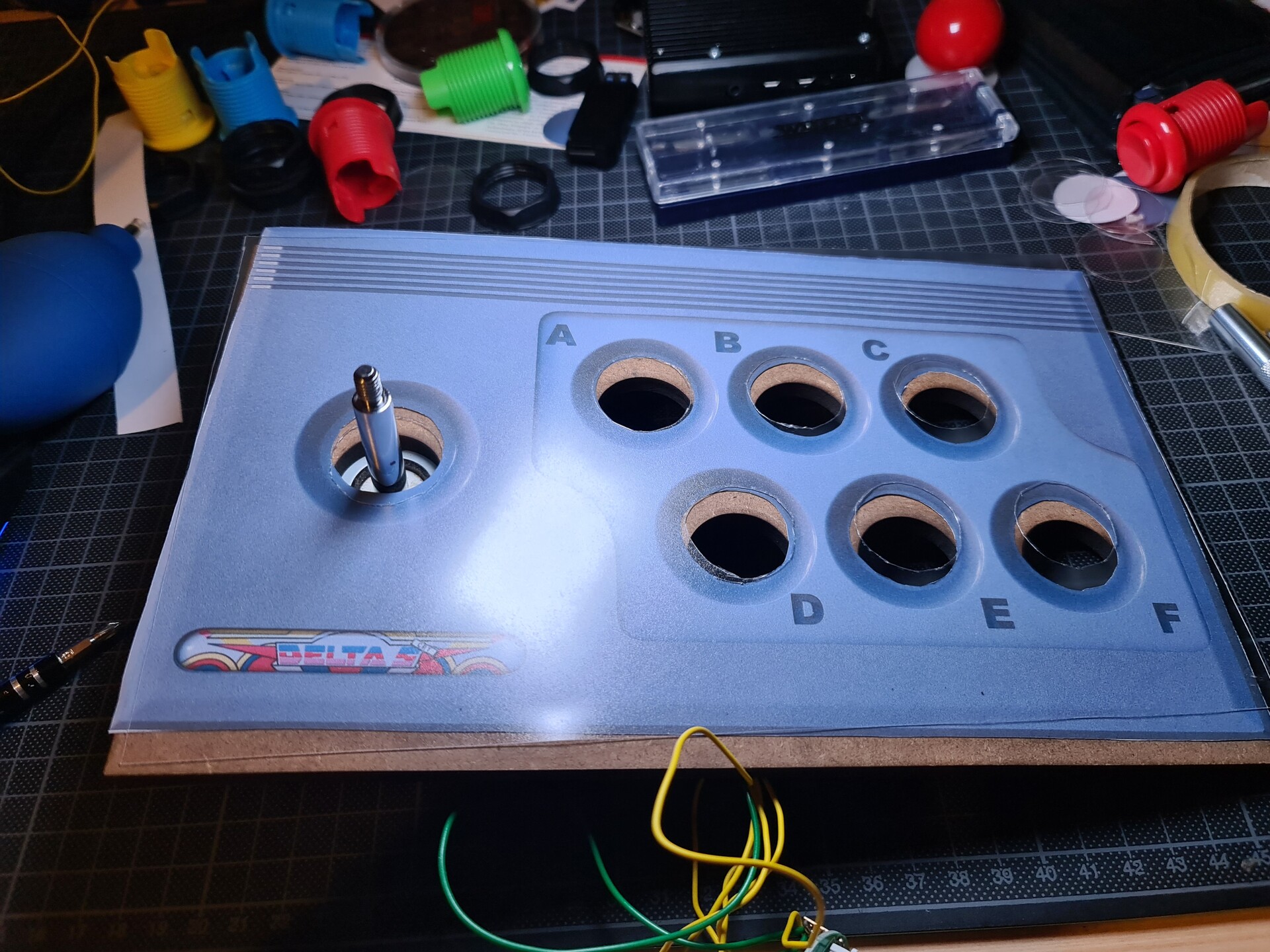
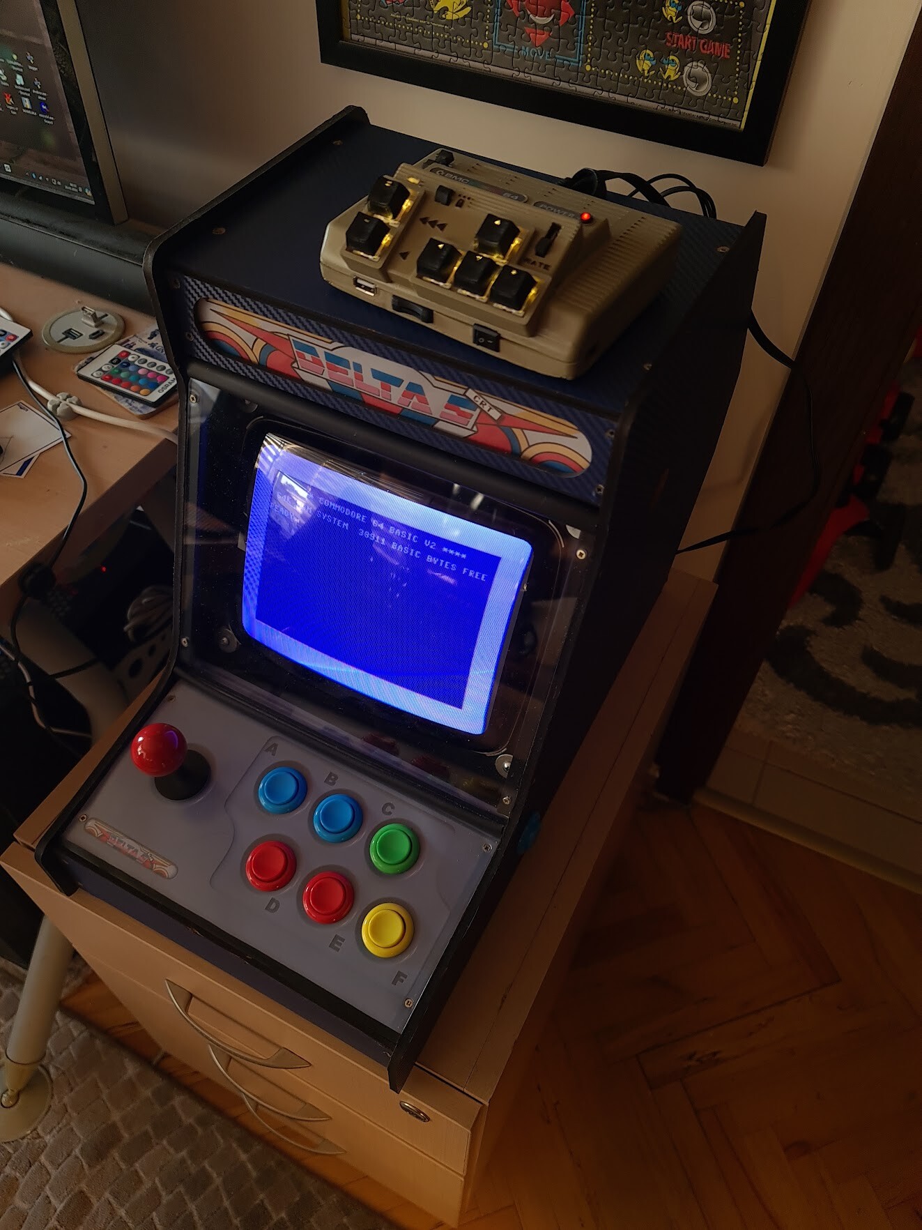
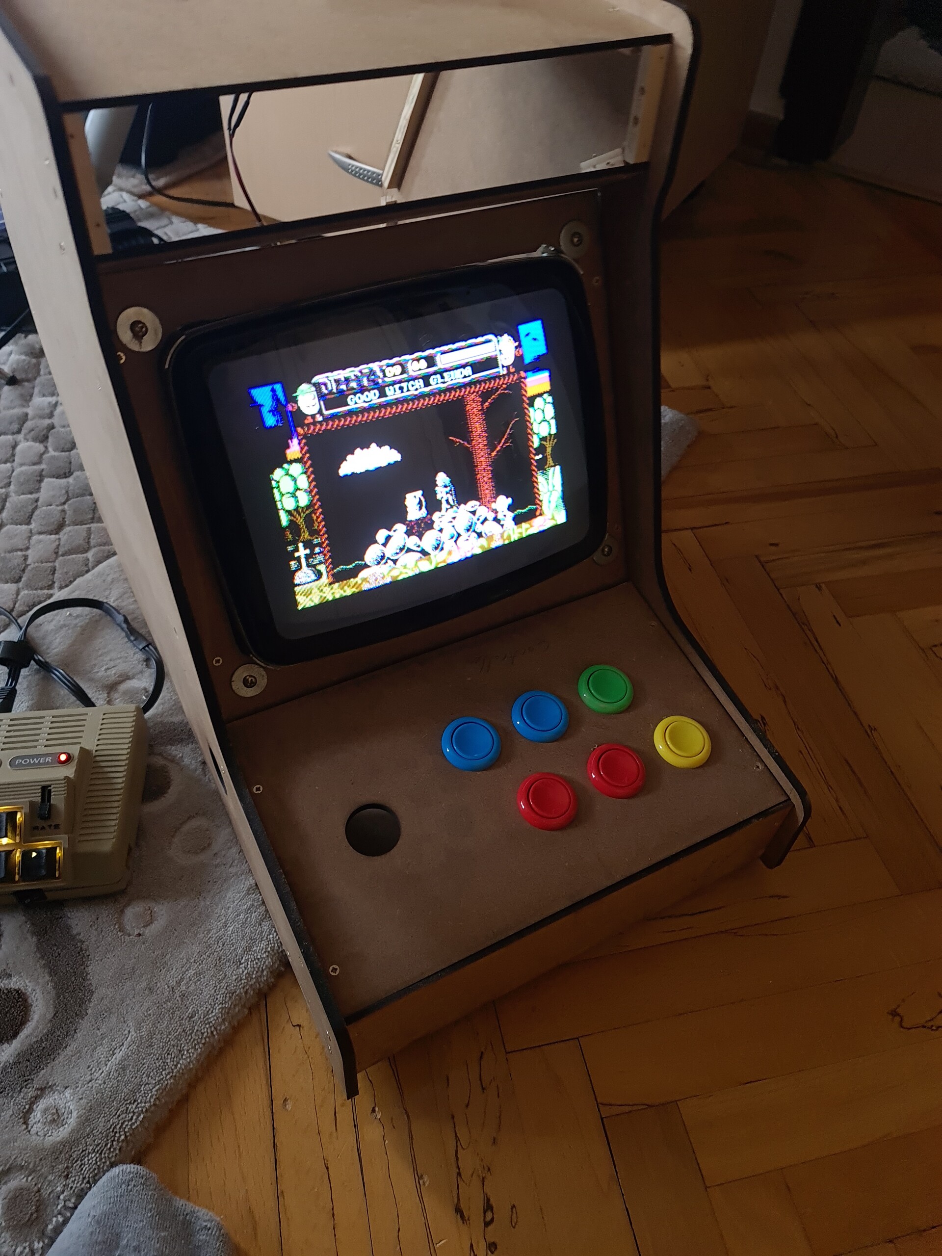
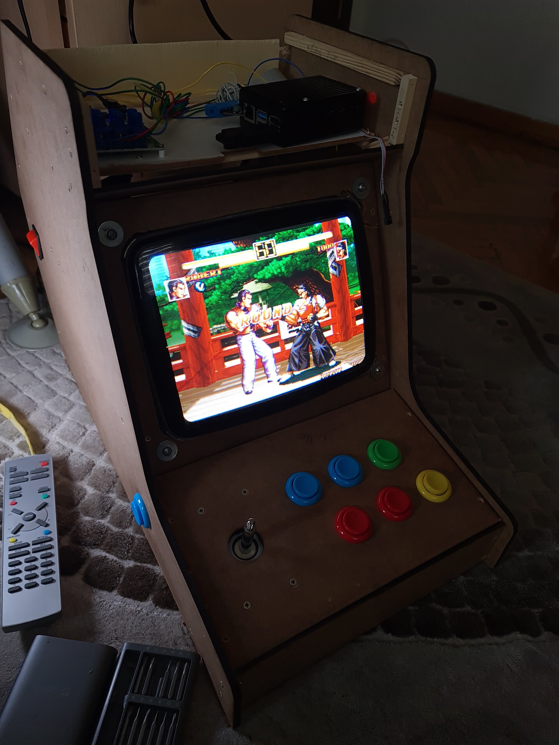
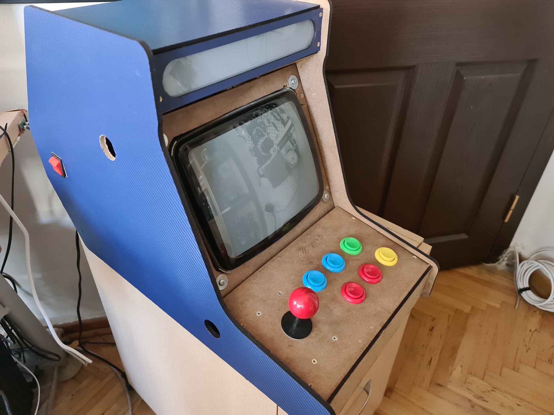
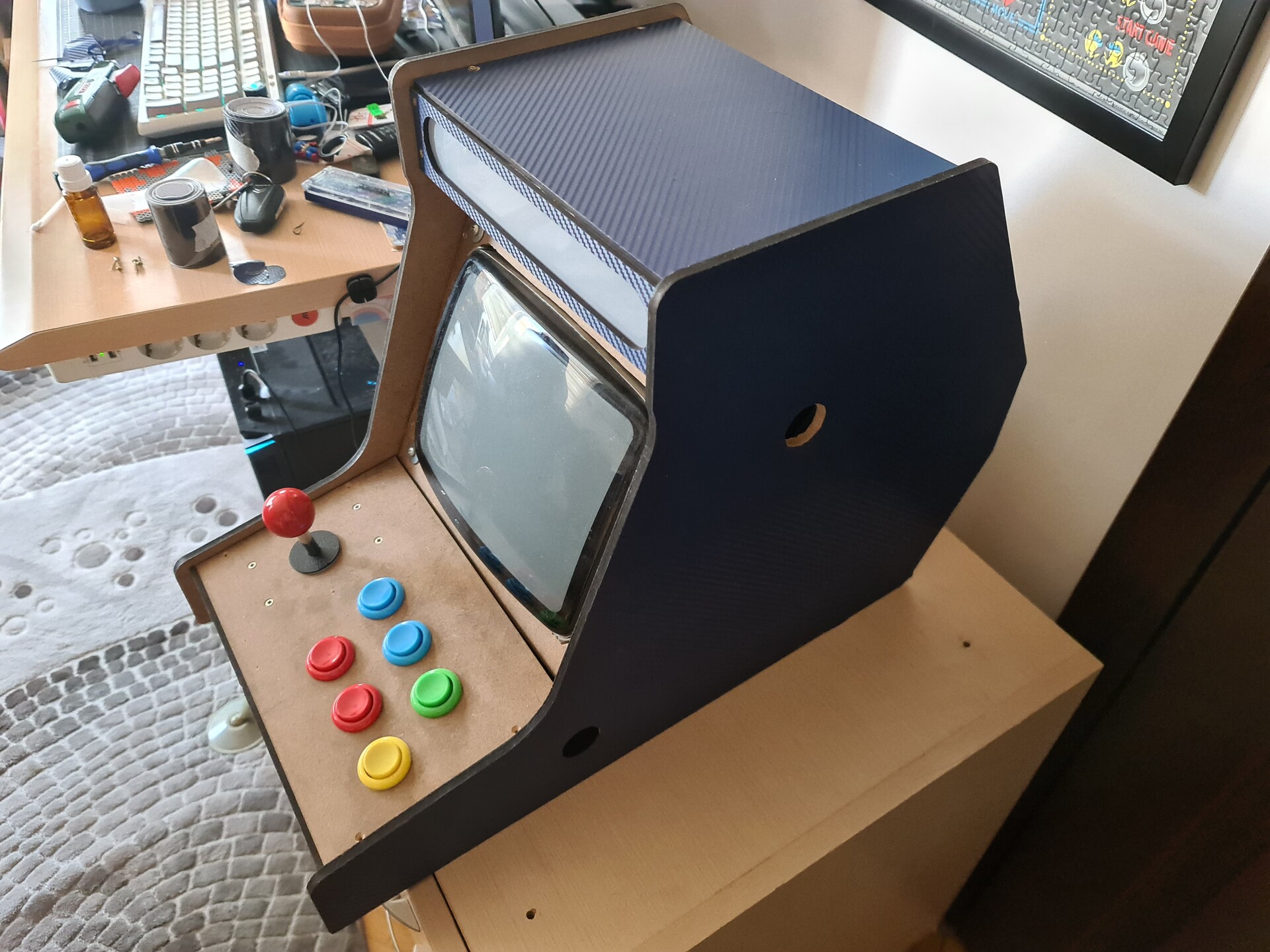
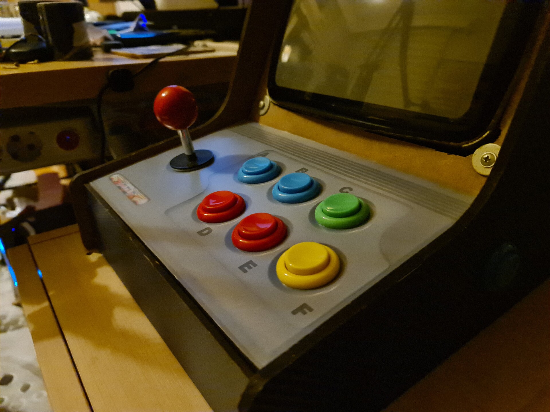
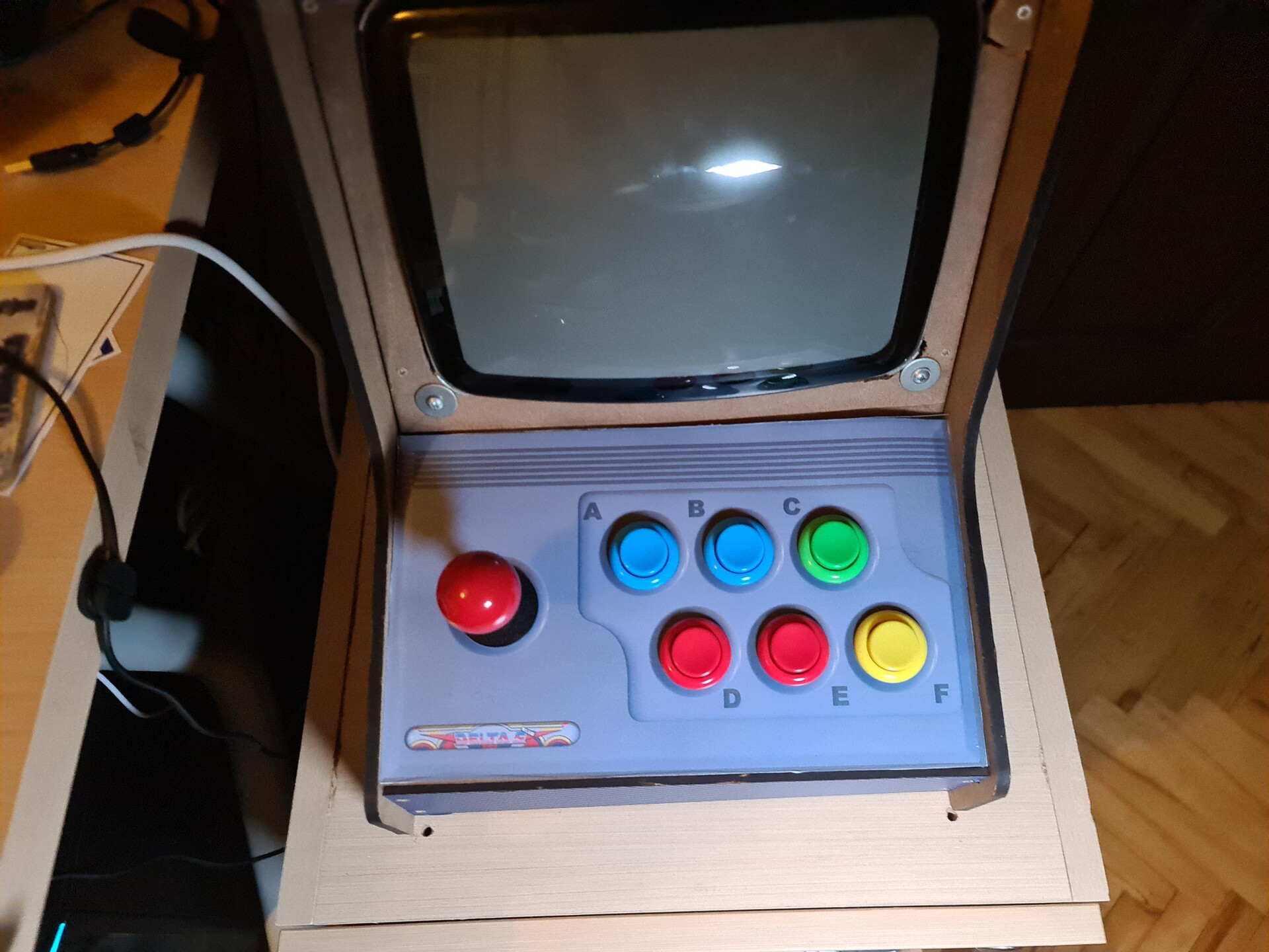
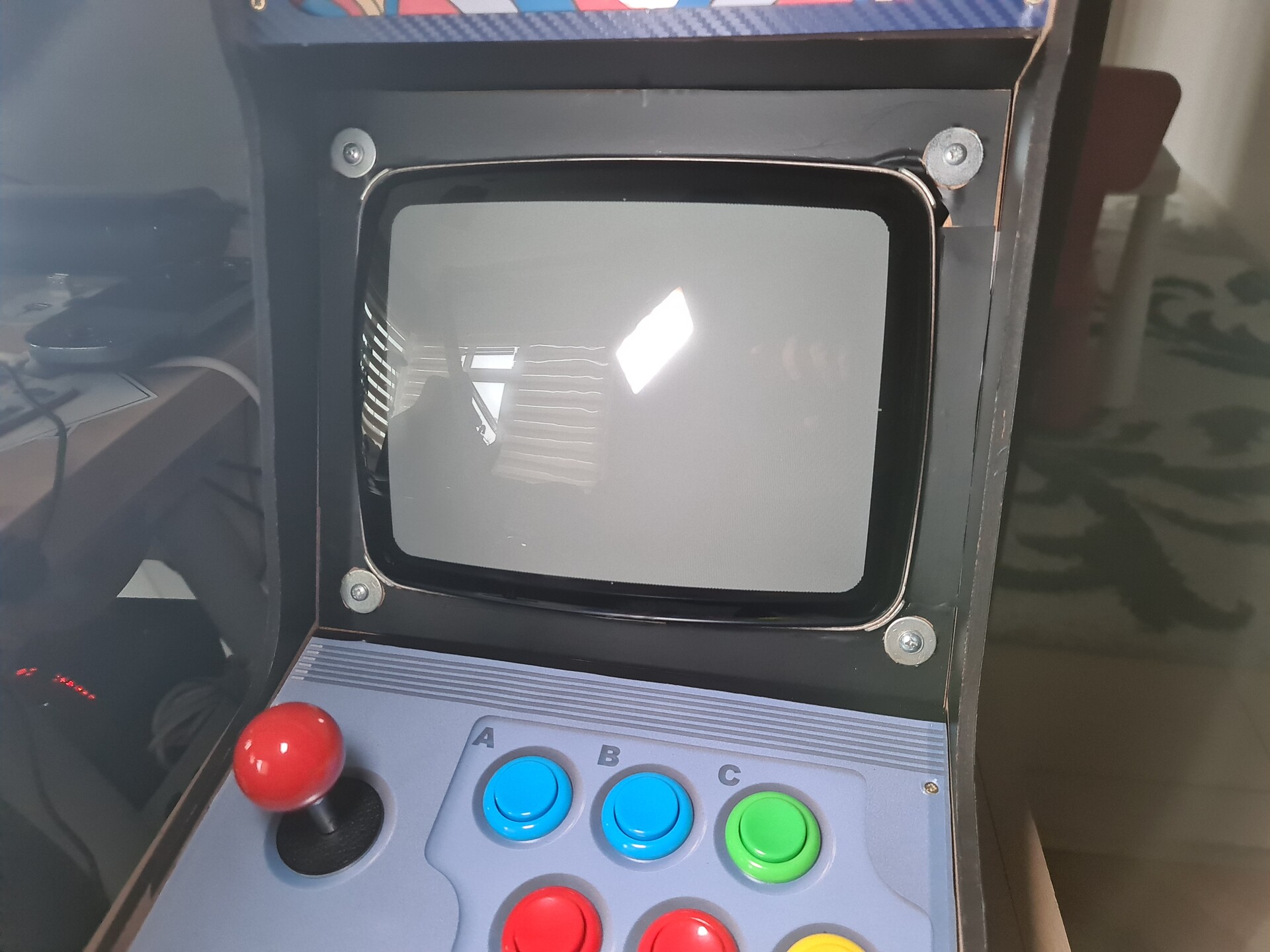
This is how it looks so far.
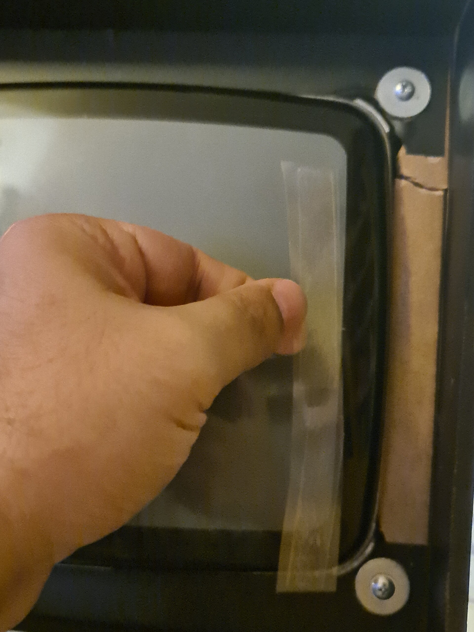
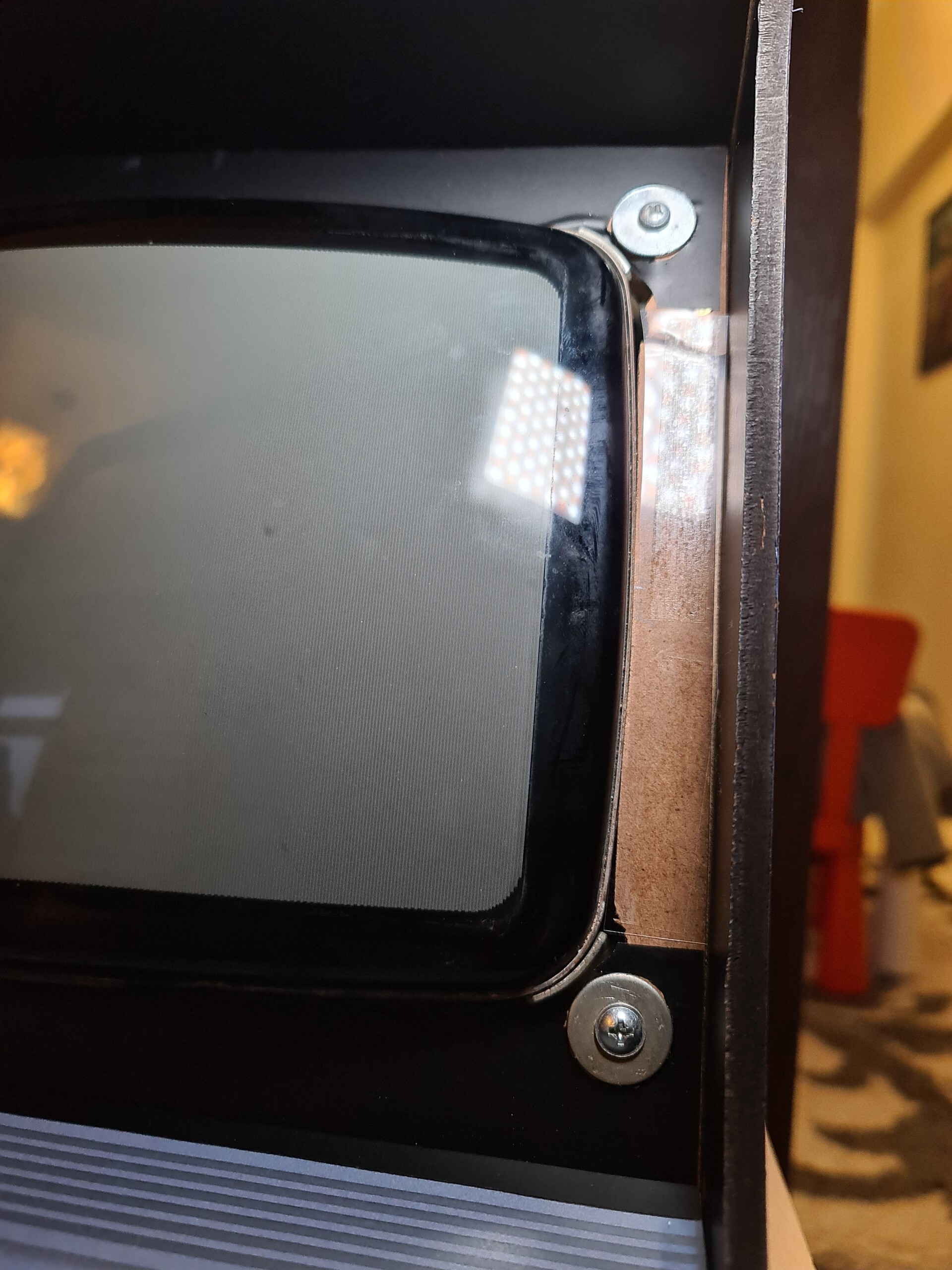
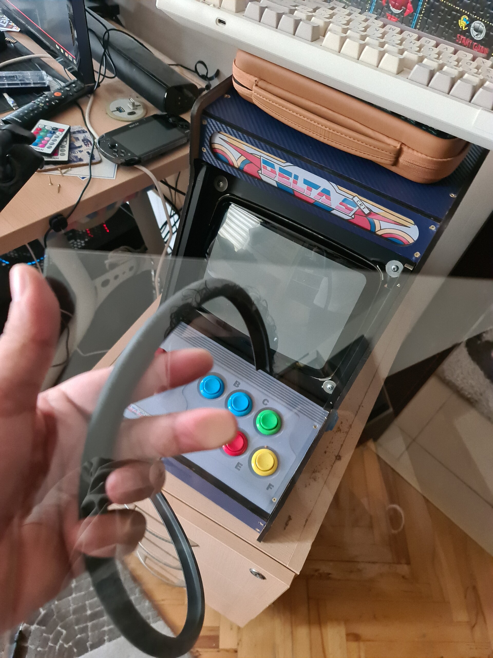
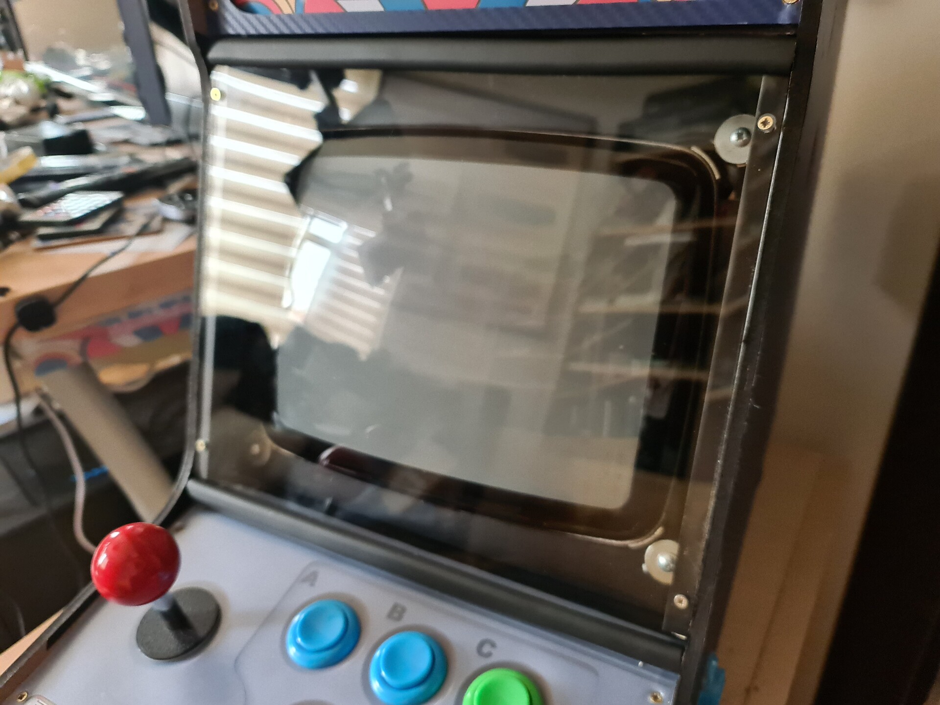
There is a screen glass I ordered for cutting and it will be placed over the actual screen. But before fixing it over the CRT screen, I needed to cover the area around the screen with black sticker vinyl.
Since I badly cut the frame around the screen, I applied some pvc sheet over the gaps between the screen and the frame by double sided tape.
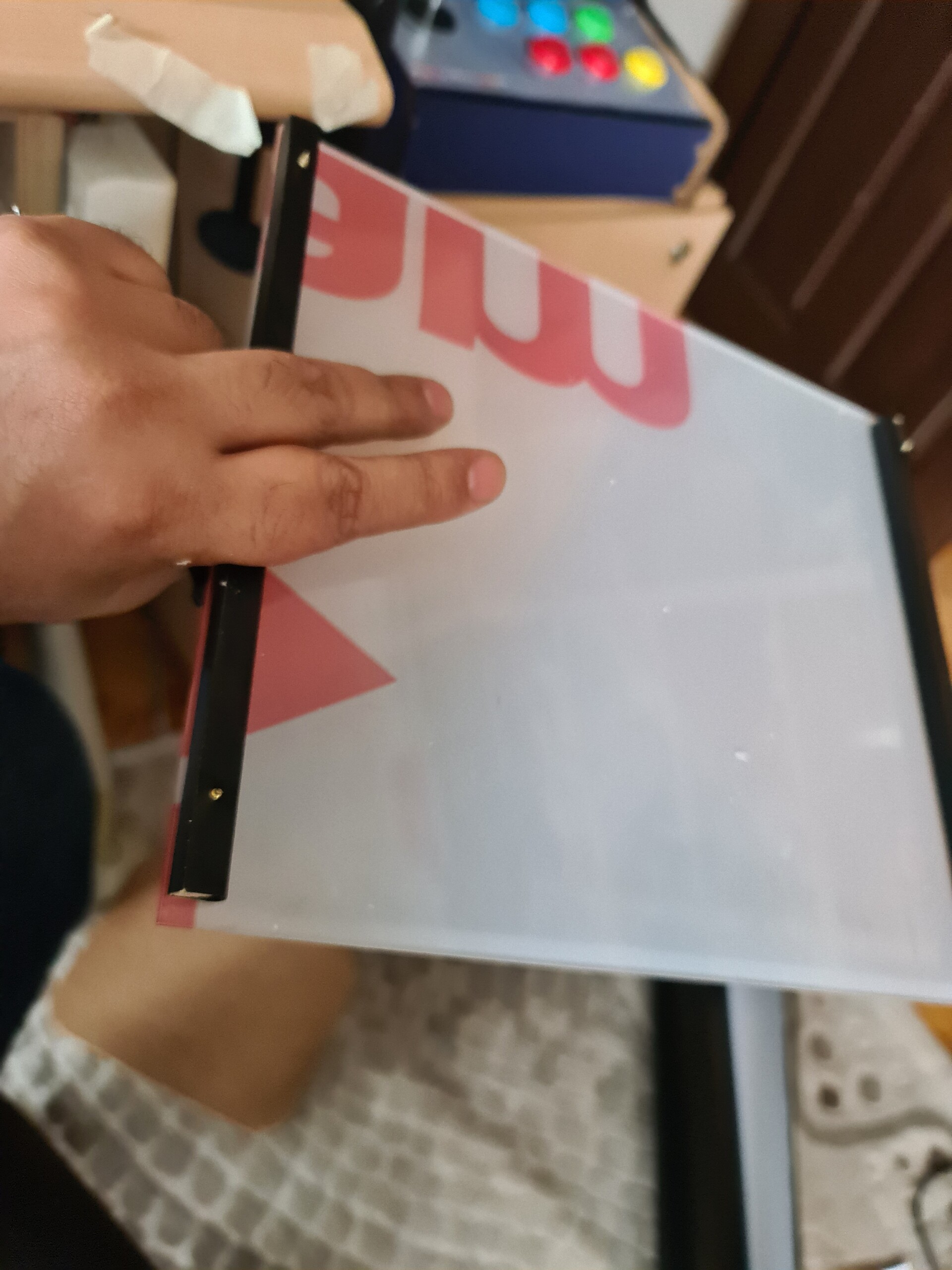
After that, I covered a lath with the same black vinyl and fixed it to the plexiglass with screws. And then I drilled and screwed the laths that attached with the plexiglass to the cabinet side boards.
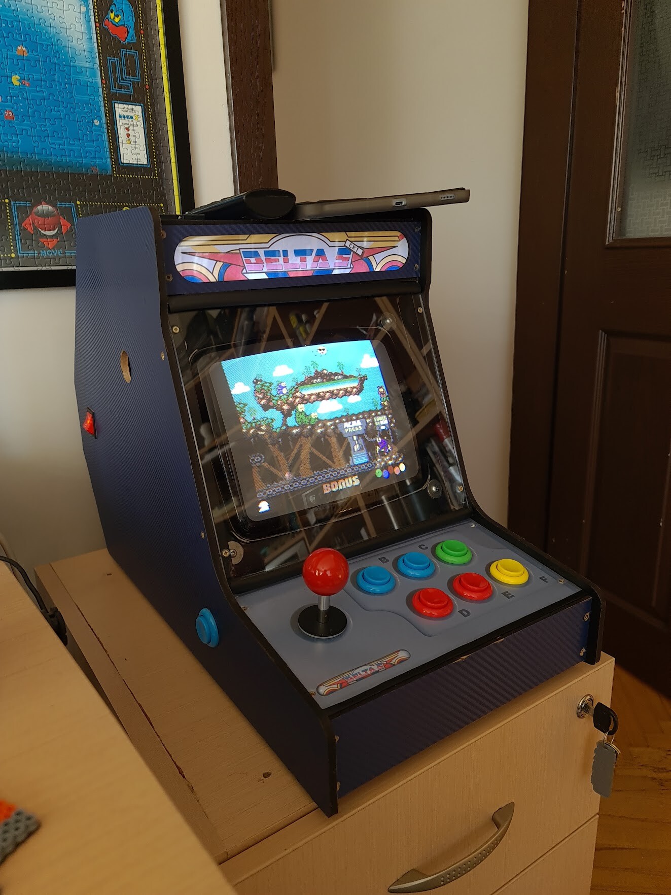
I had some rubber corner protection stripes that sold for protecting children to get injured by the sharp corners of the home furniture. I fixed that stripes to the screen glass edges.
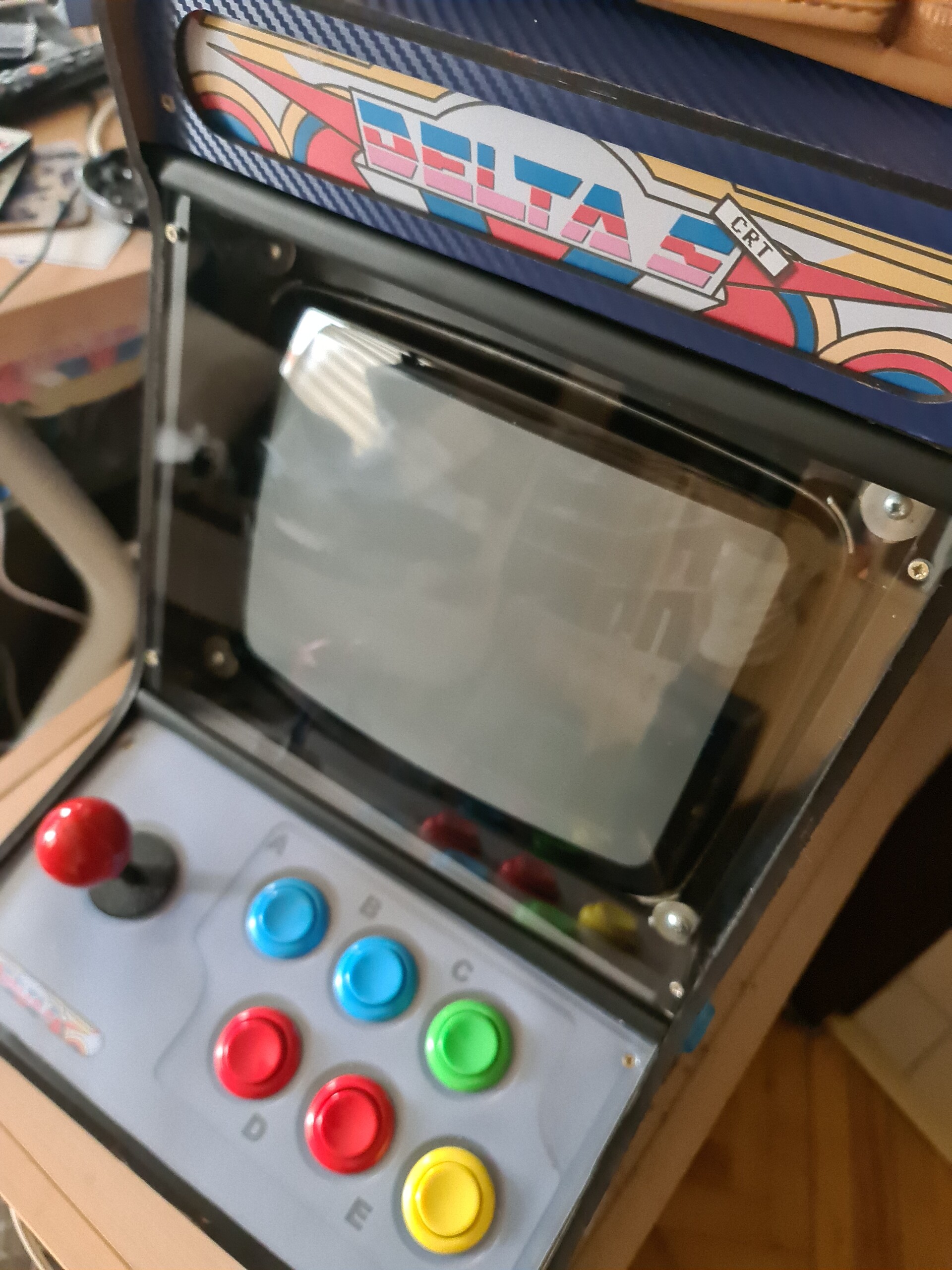
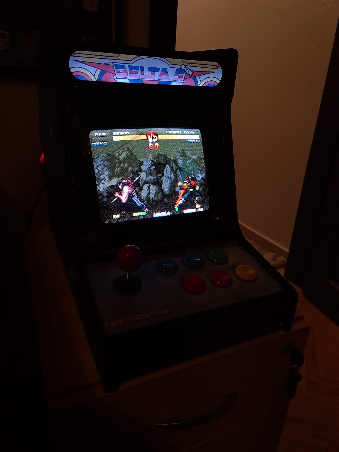
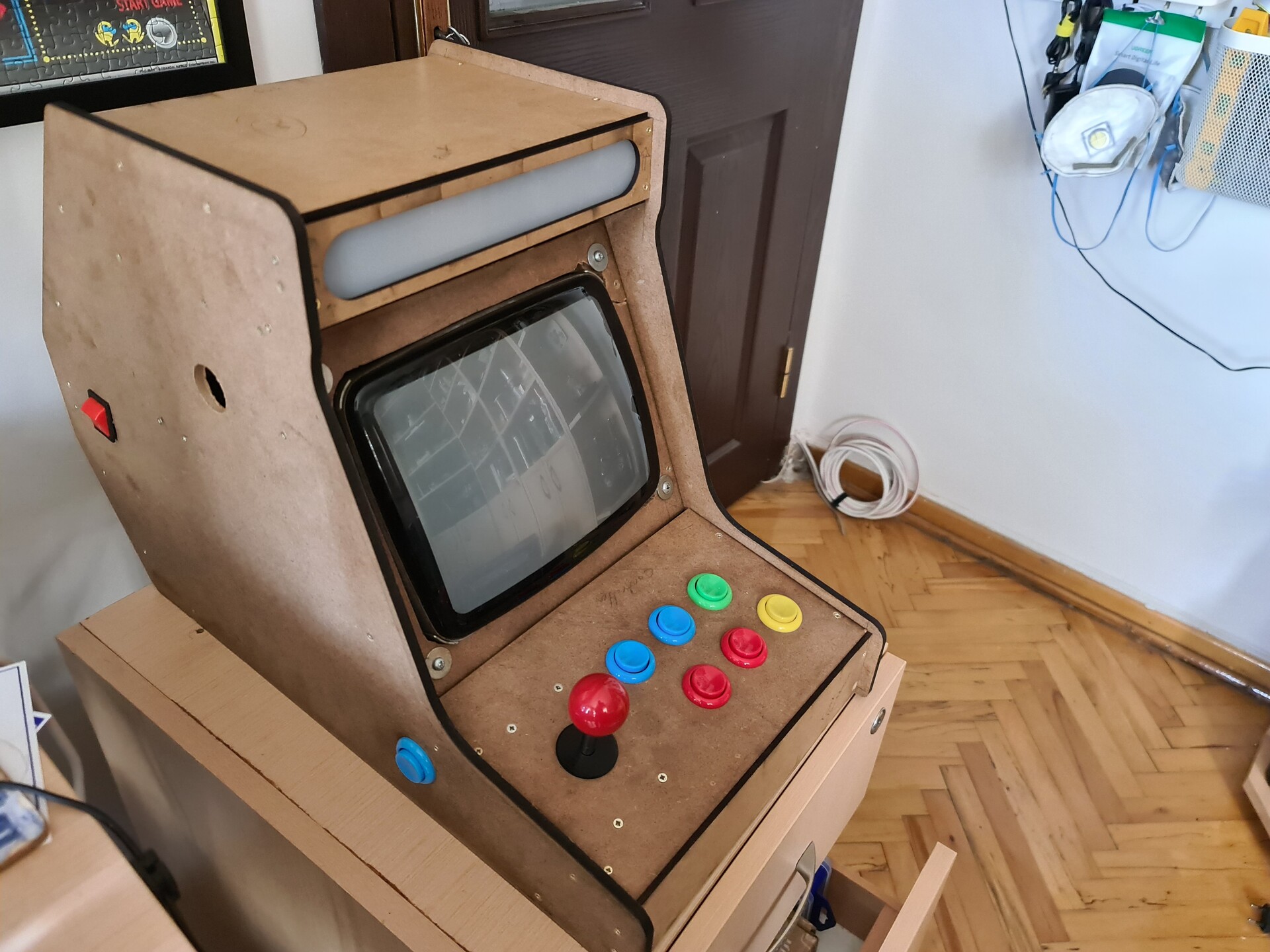
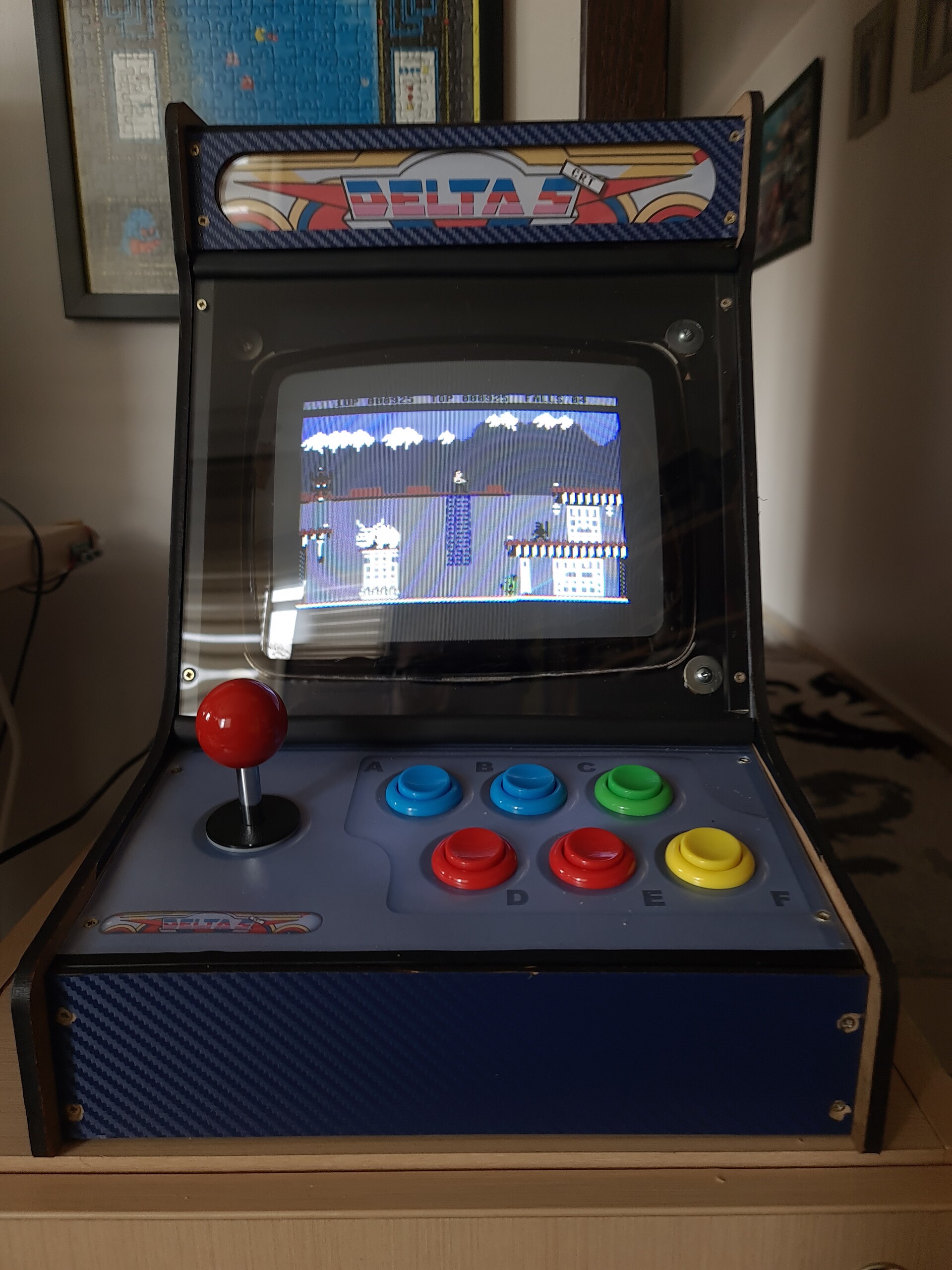
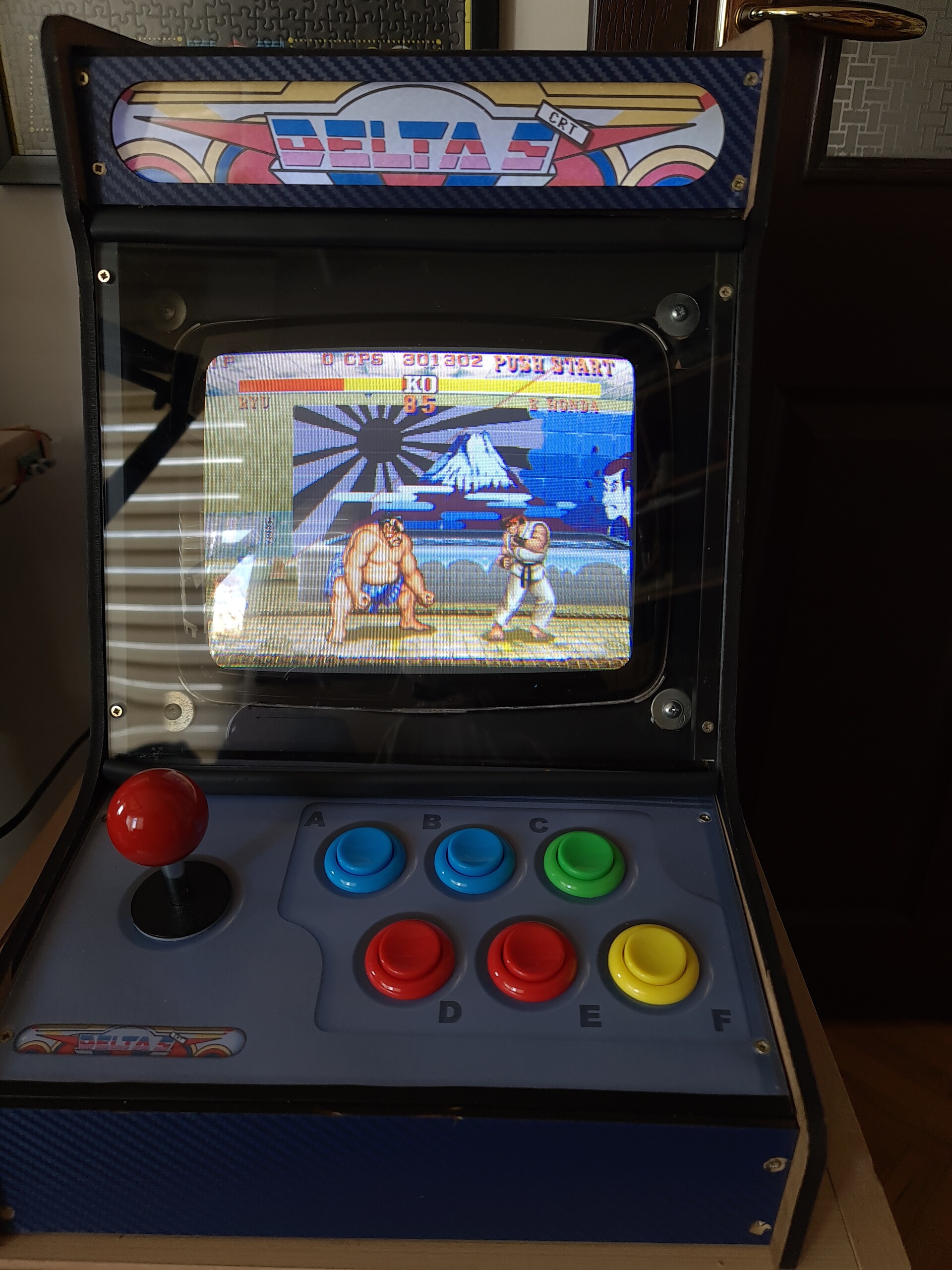
Looks better!
A quick tesy by my son.
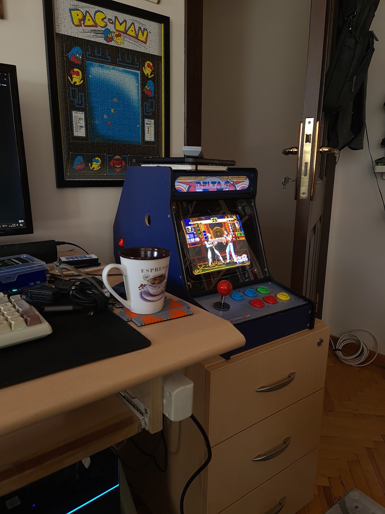
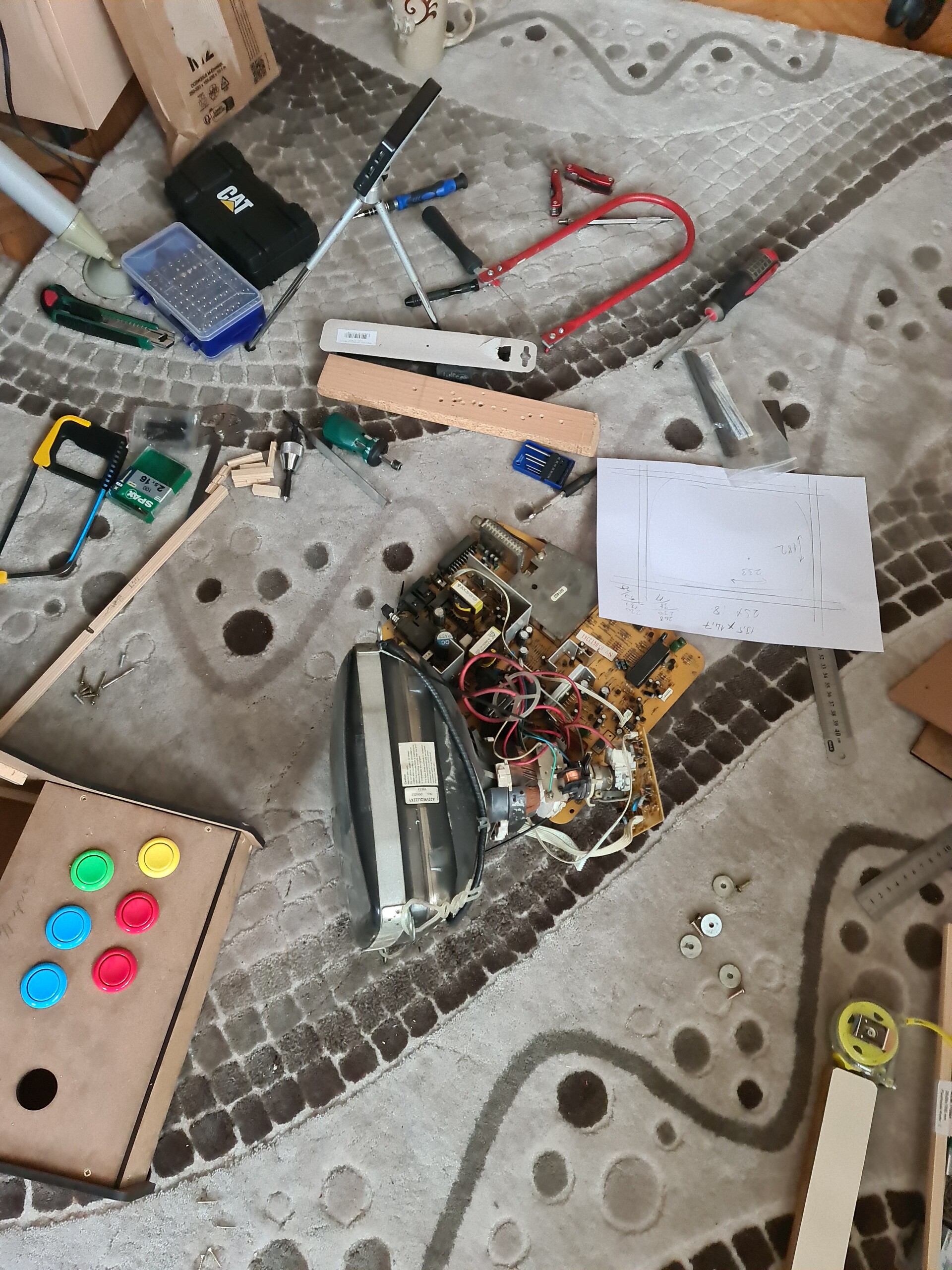
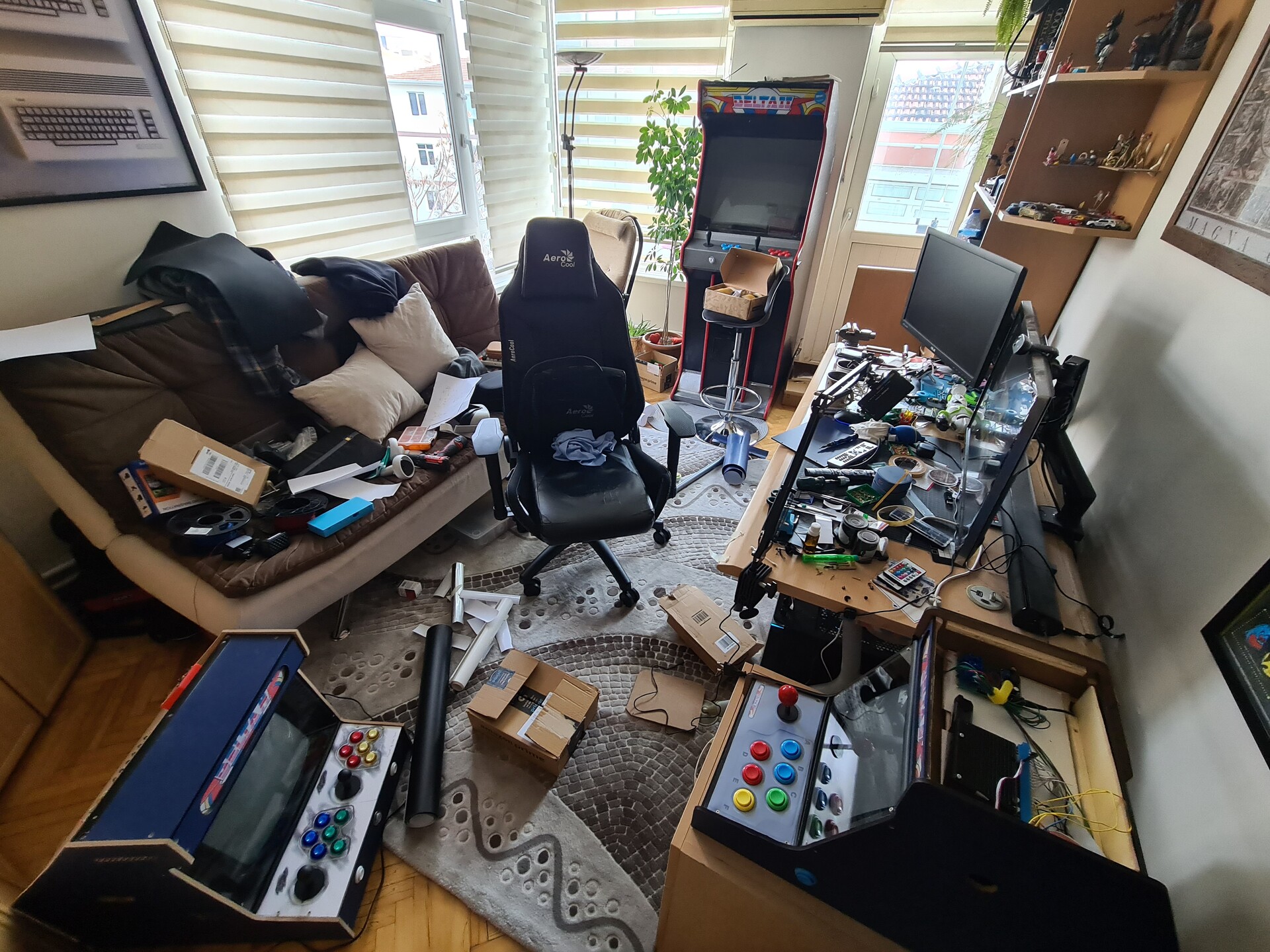
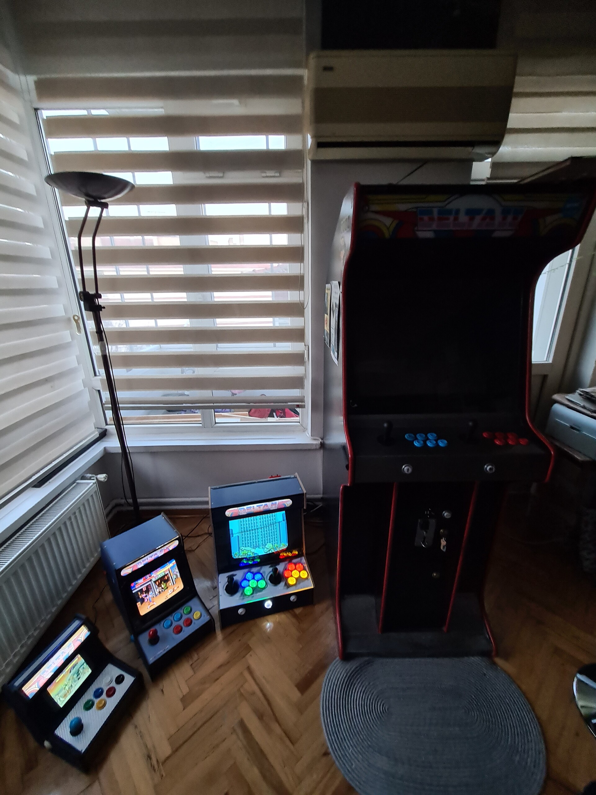
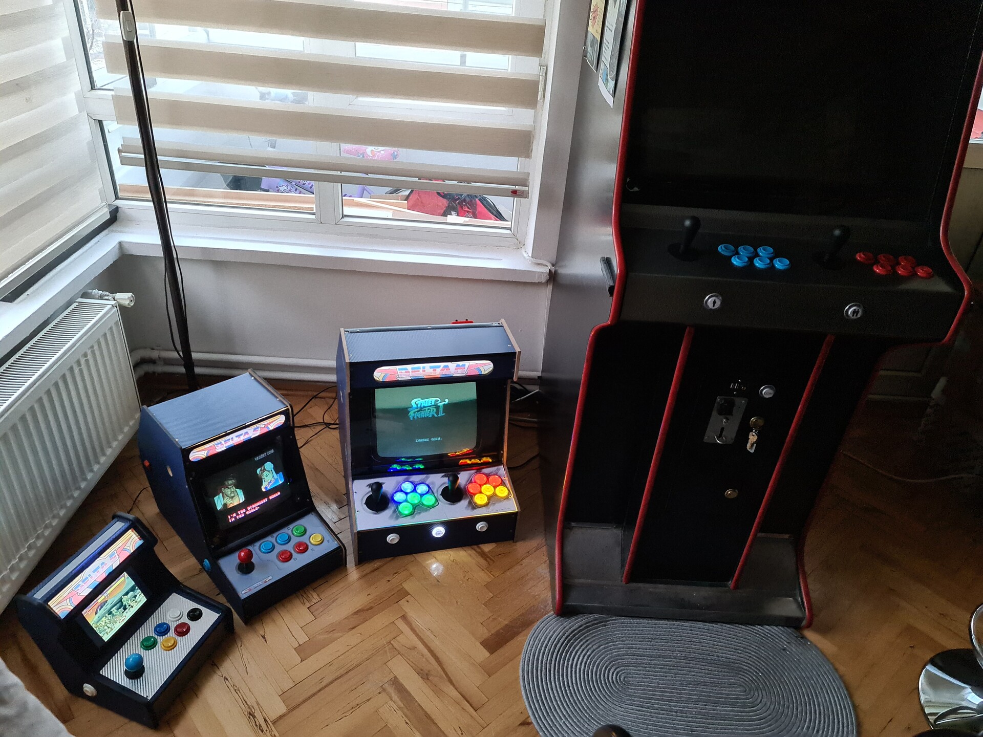
Meanwhile the study room is devastated.
As some final touches, I added an LED strip for the Marquee lighting.
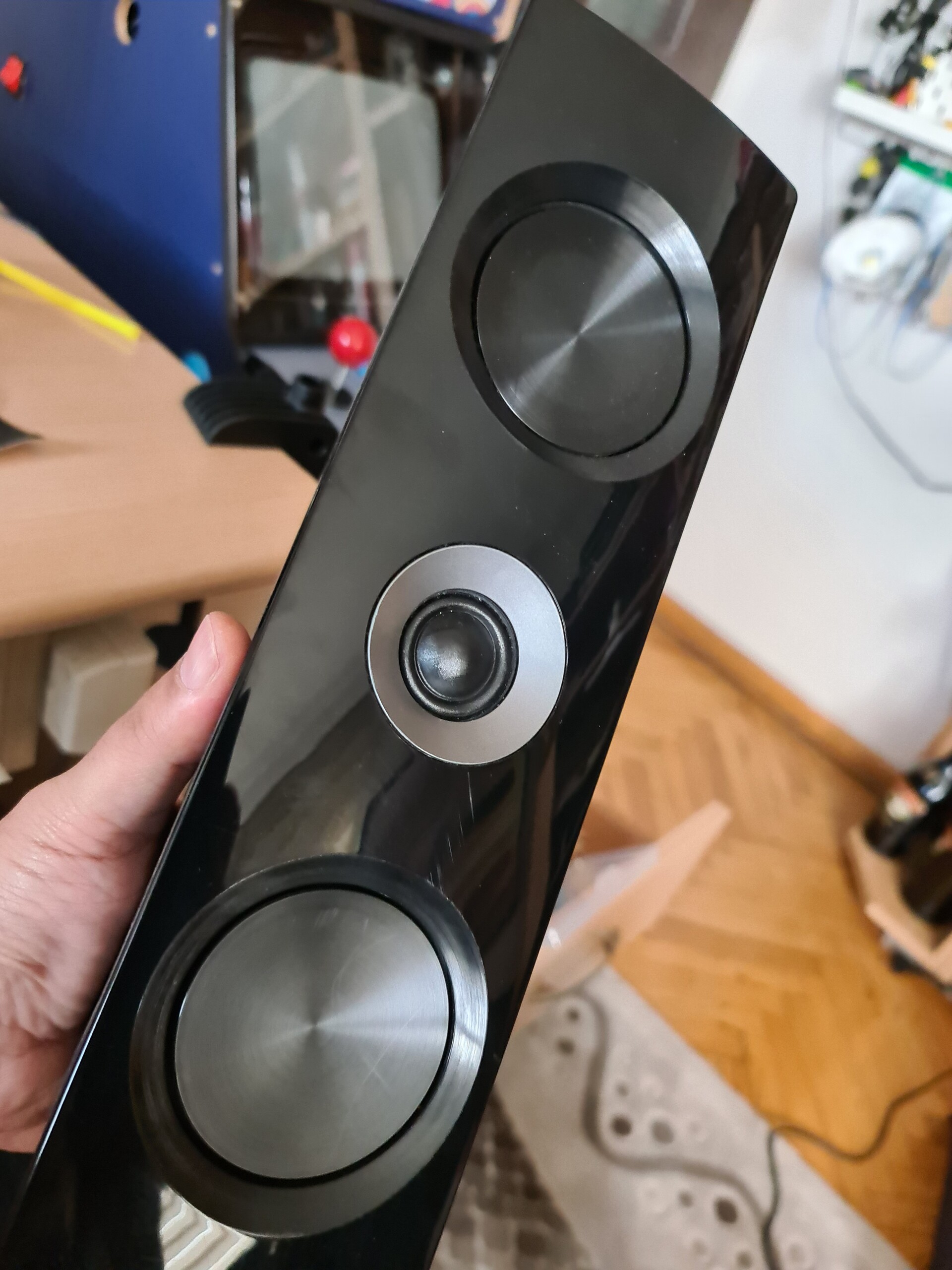
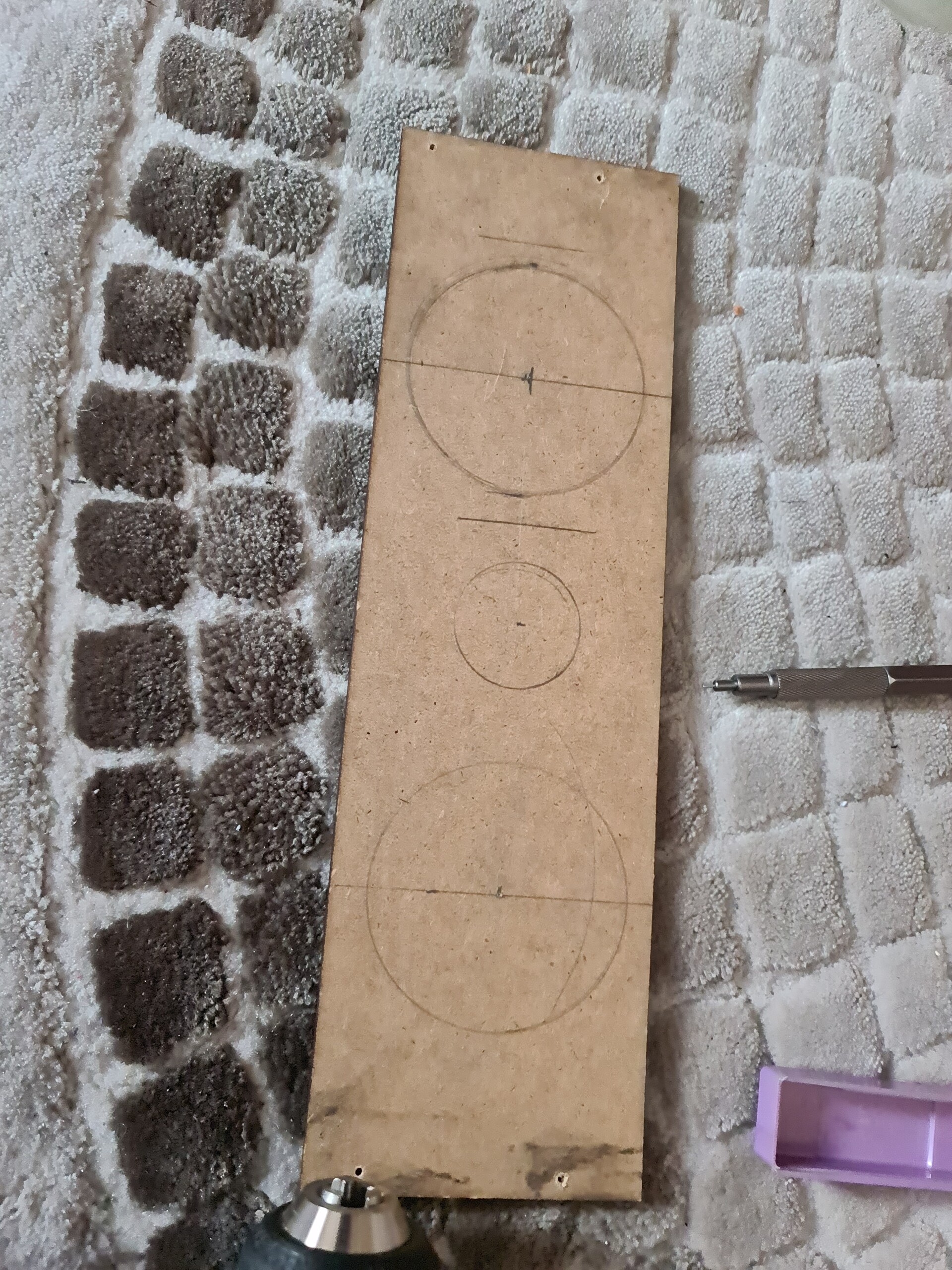
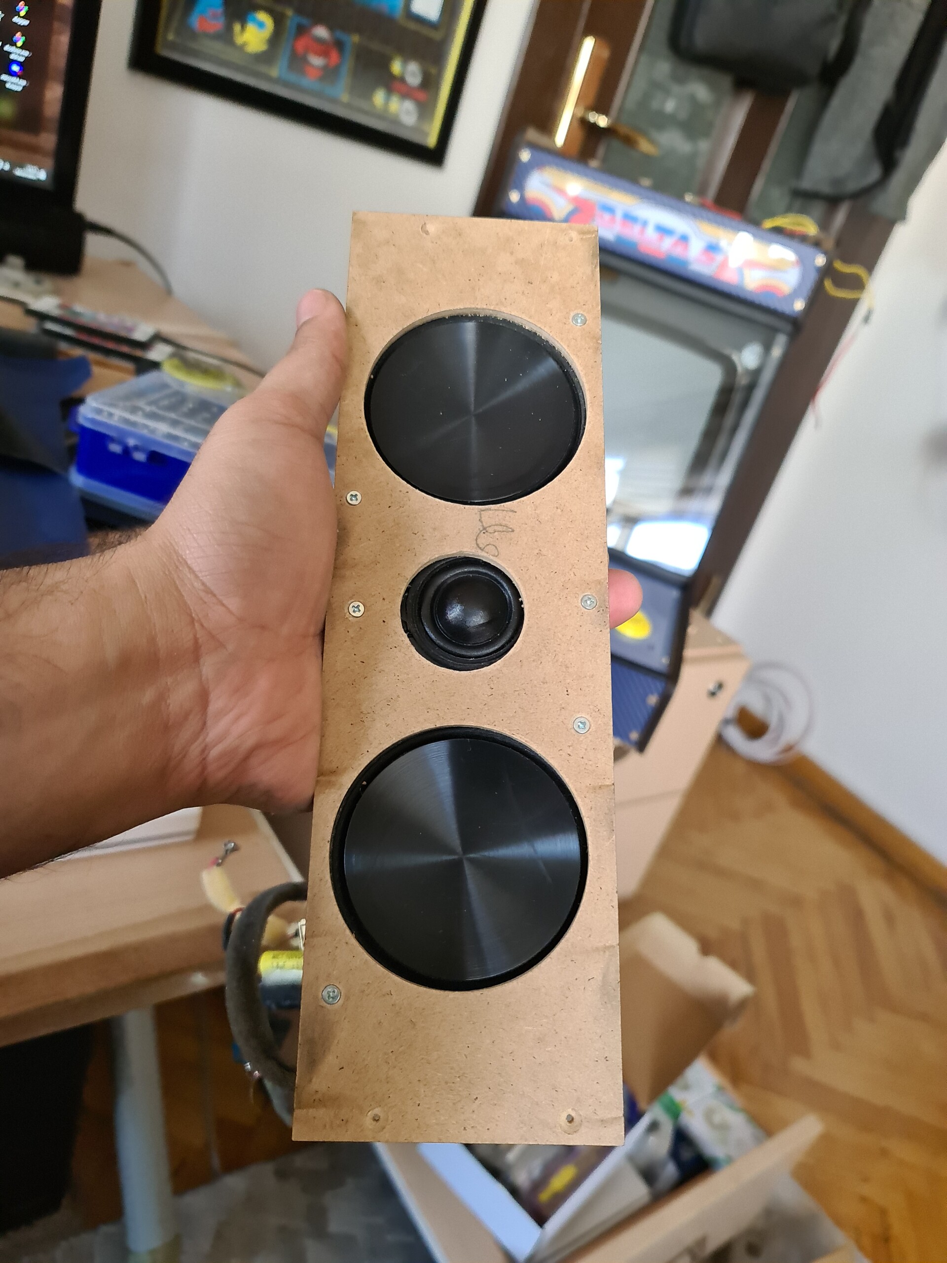
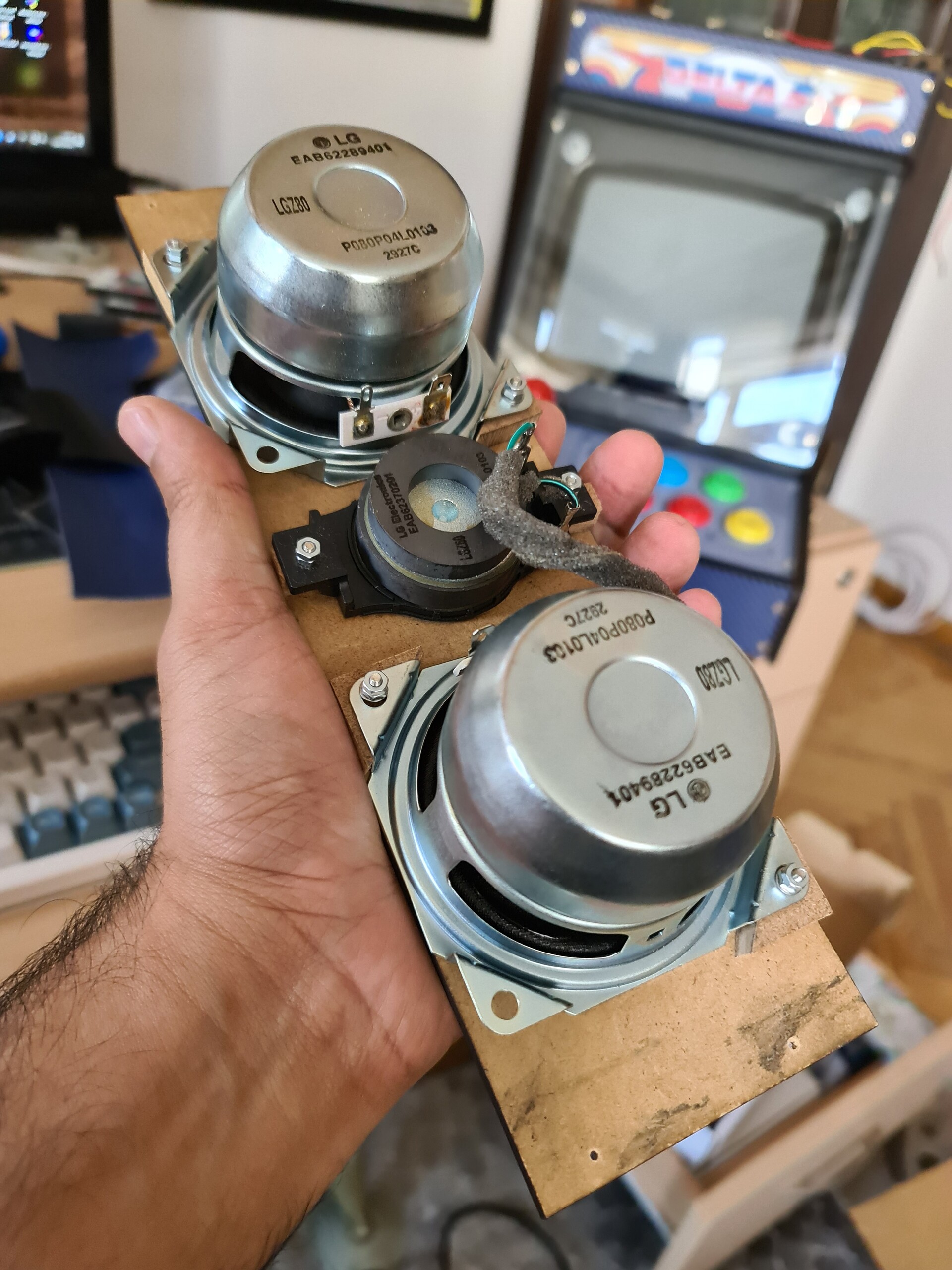
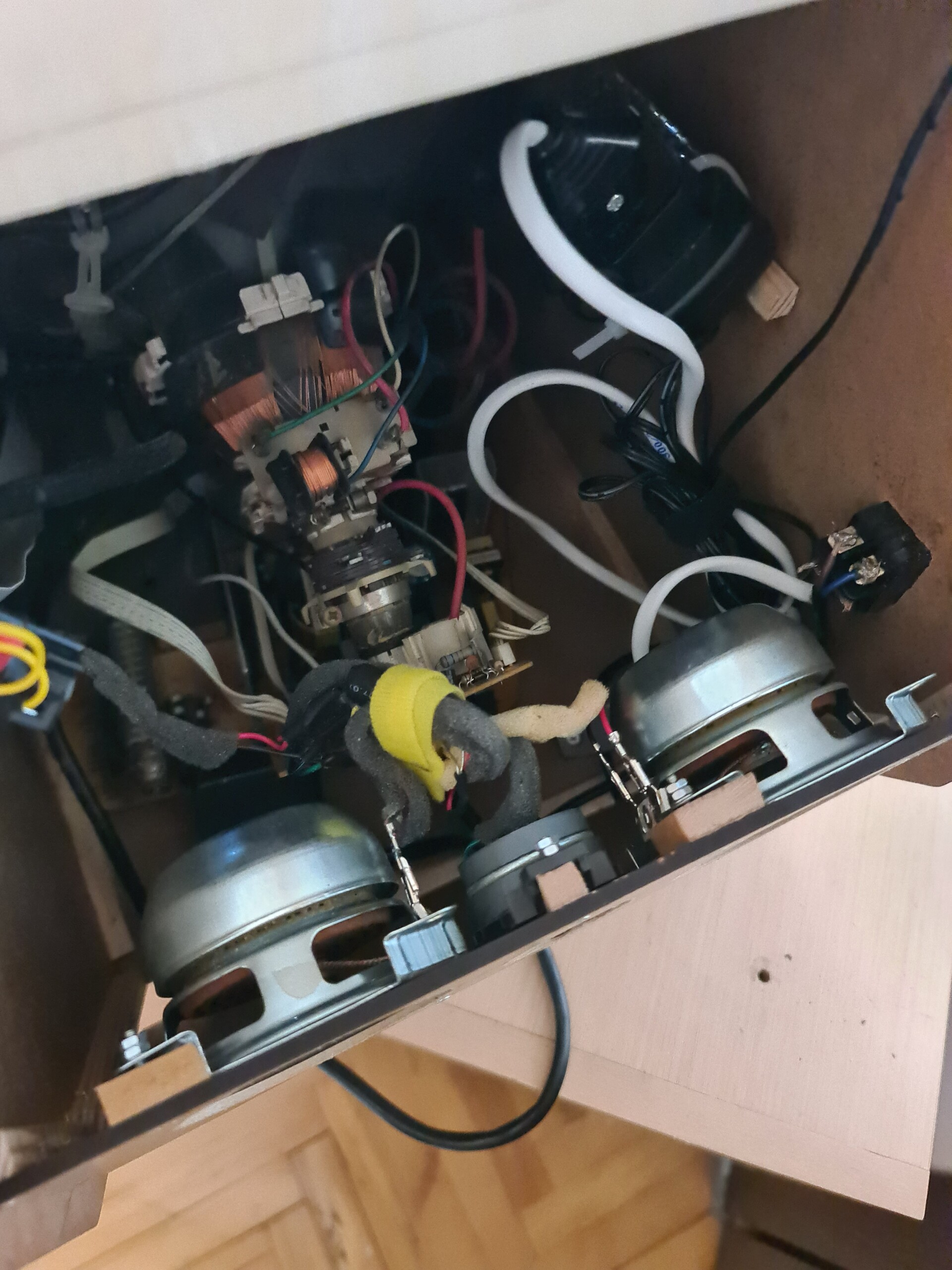
For the sound system, I had a spare speakers that I had by my old broken hometheater system. I used center speaker set of it and fixed the speakers to the back board.
And the cabinet is ready to use. I put all 3 pieces I made so far side by side.
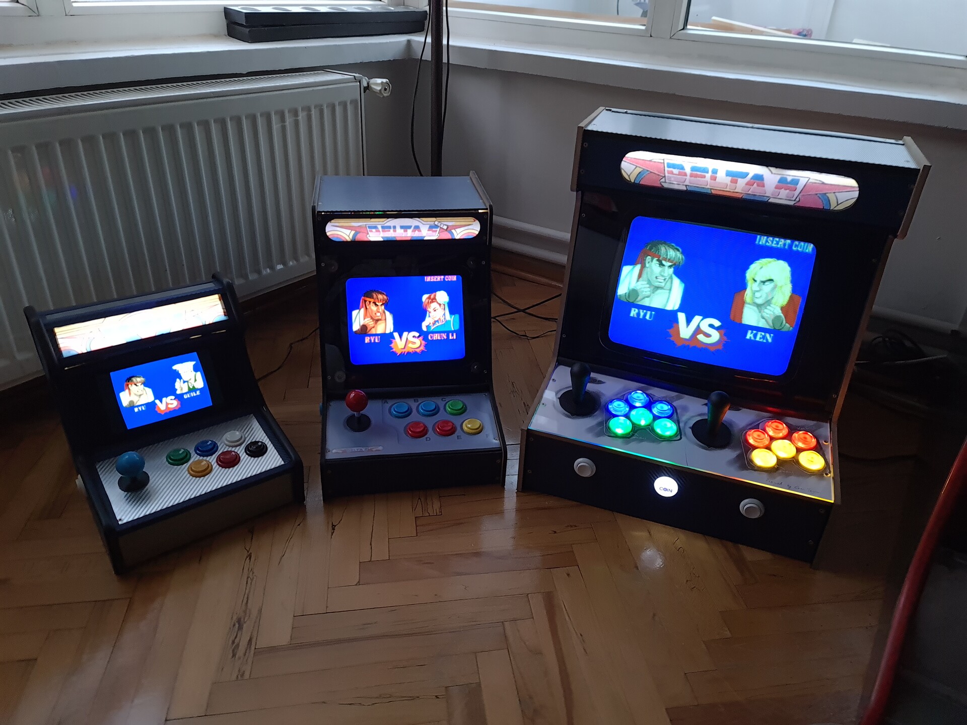
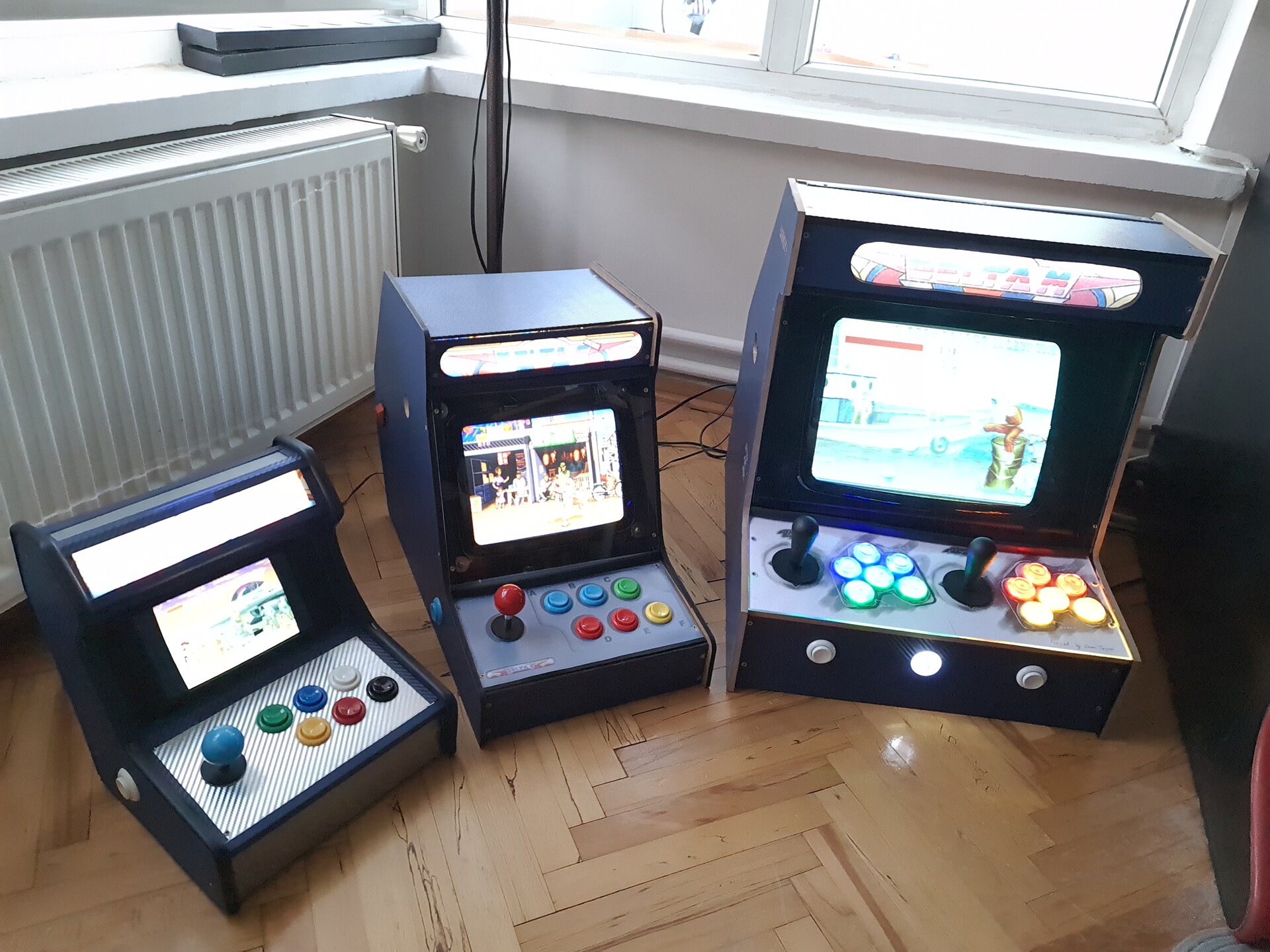
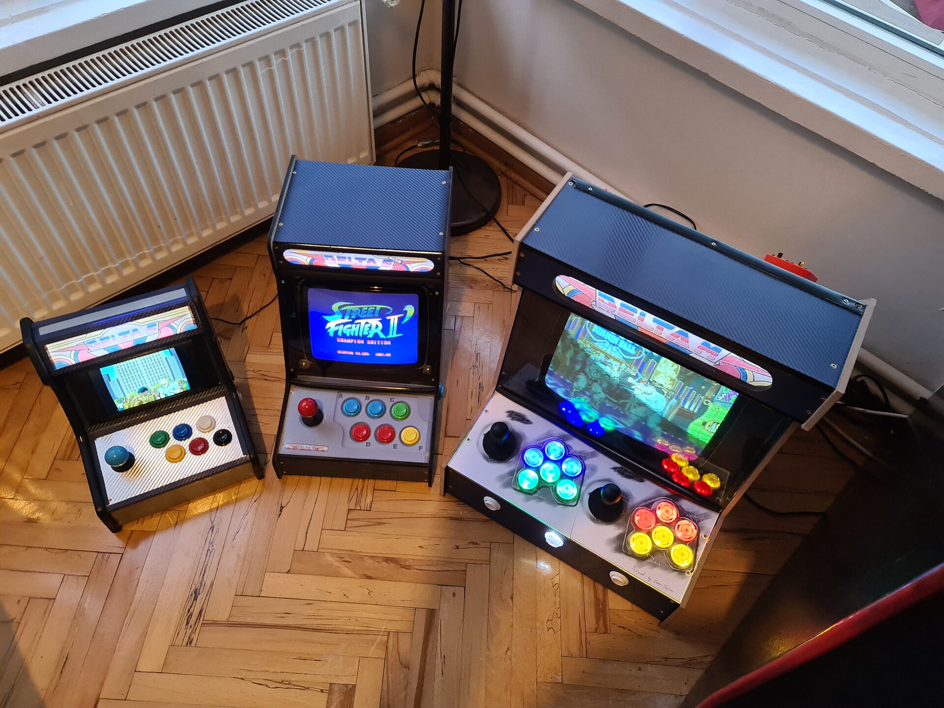
Hope you like the result, and as always, thanks for tuning in.