Adding a keyboard module to my Pixel Toaster

Making Of / 26 April 2022


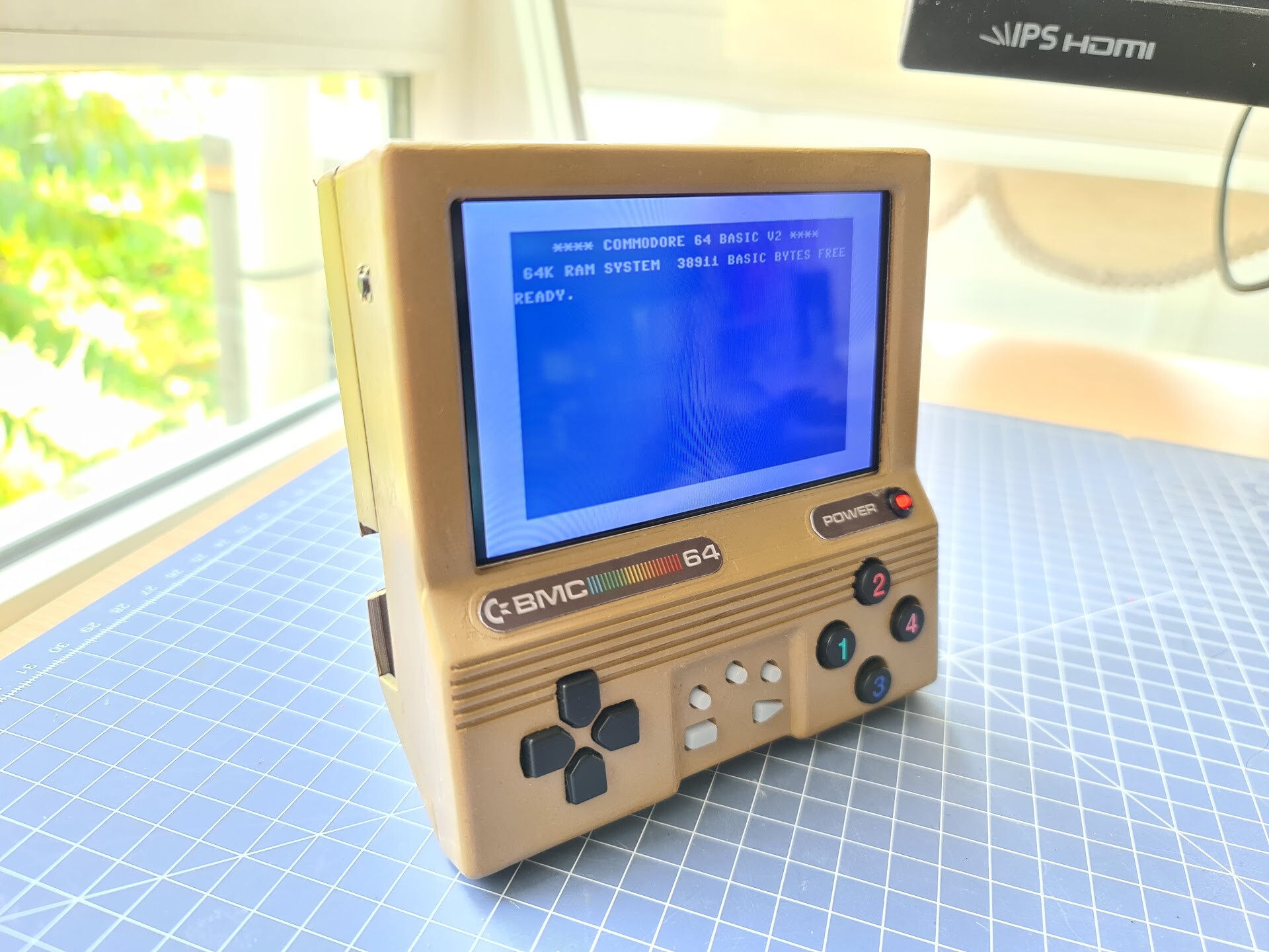
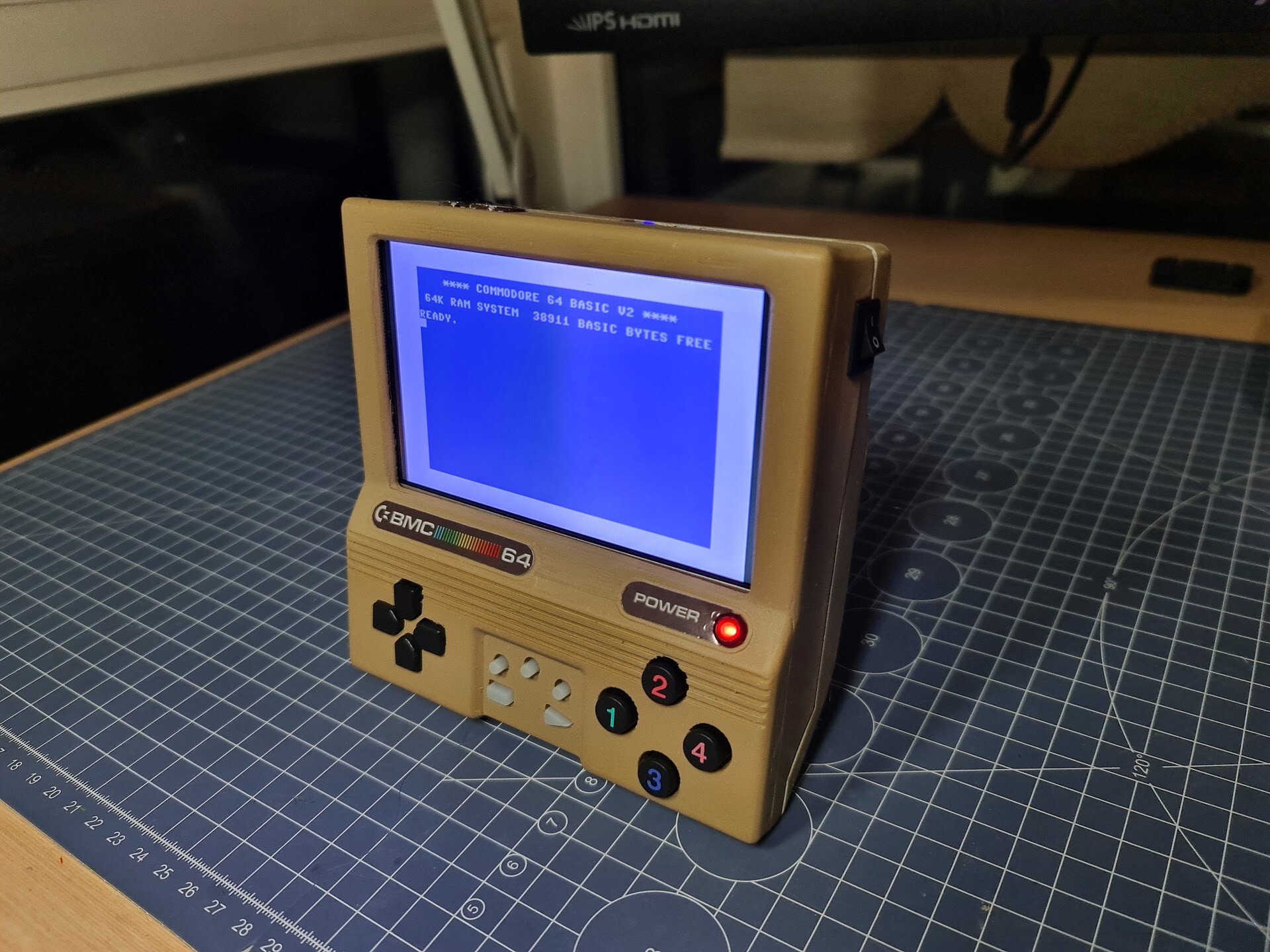
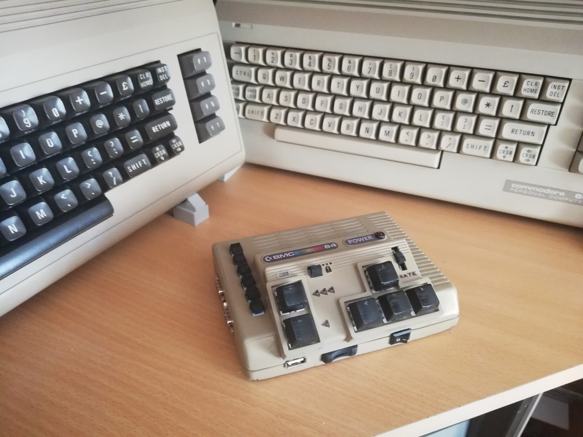
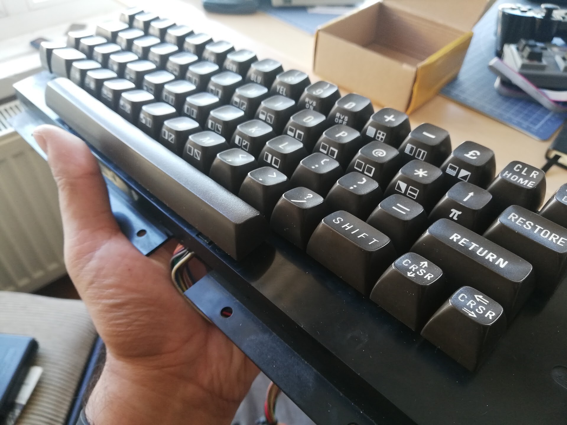
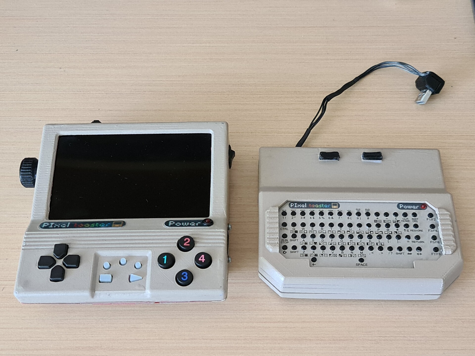
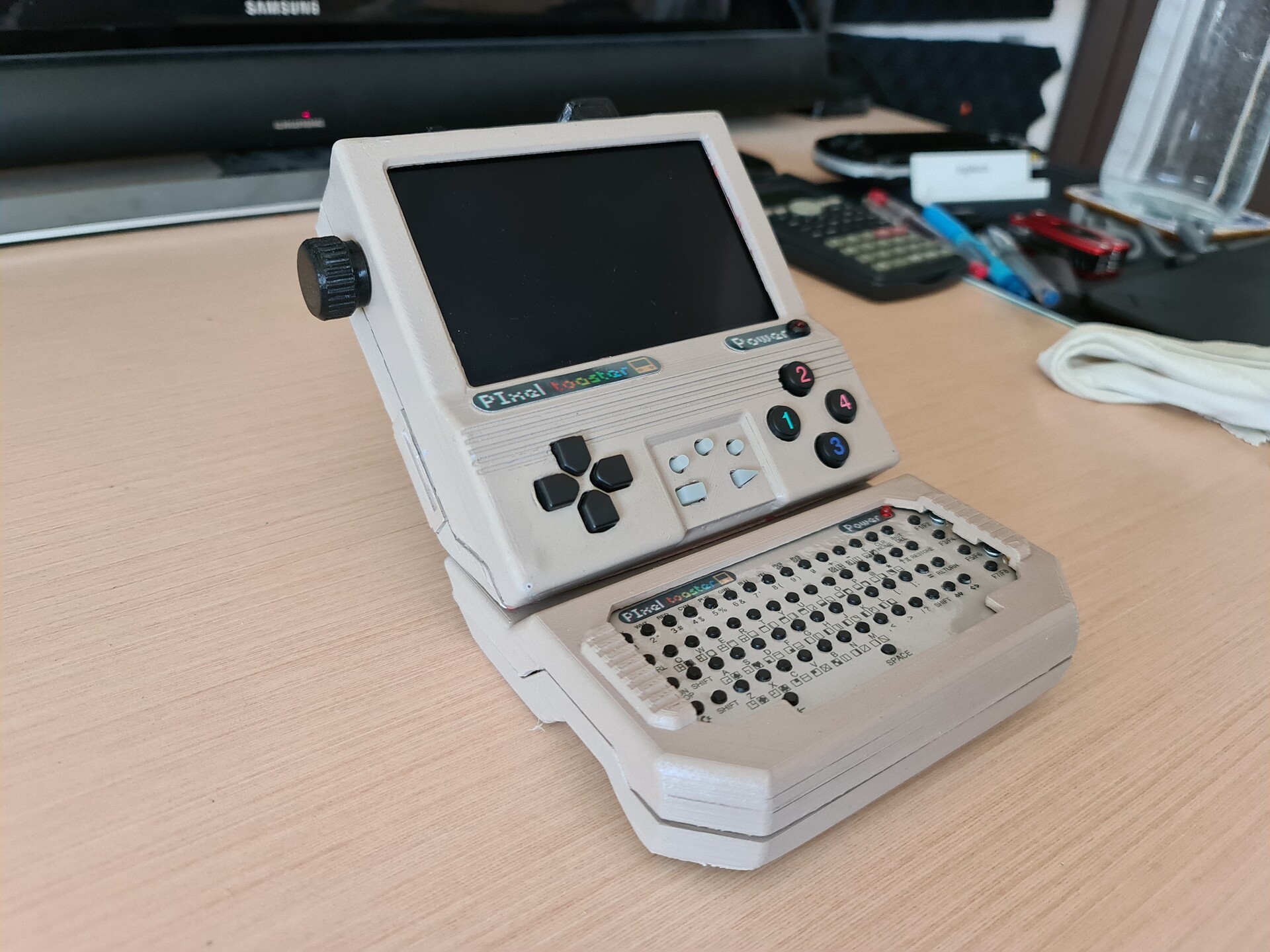
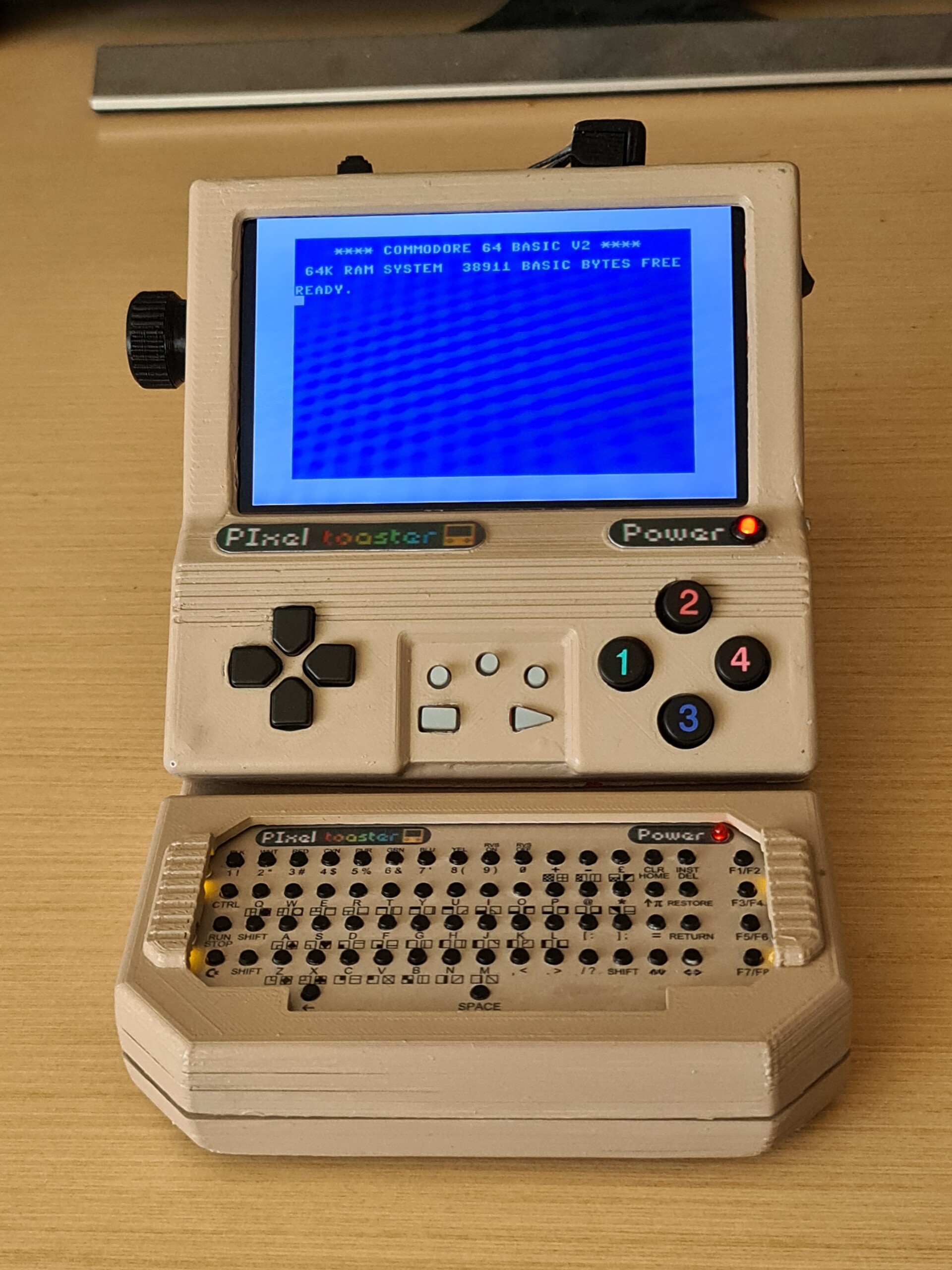
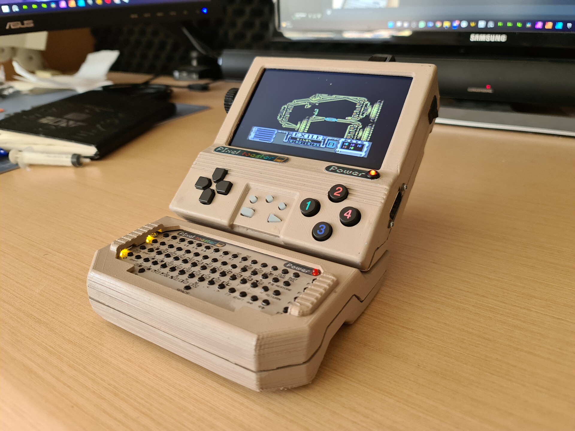
Hello! Previously I made an handheld design using Raspberry PI and 3d Printing / Painting. This time I added a detachable keyboard module to my console so it would be easier to access whole c64 keyboard and experience.

You can check the making of process by this two links:
https://www.artstation.com/blogs/blockmind/lMOo/making-of-handheld-commodore-64-project
https://www.artstation.com/blogs/blockmind/lMee/handheld-commodore-64-project-finalization

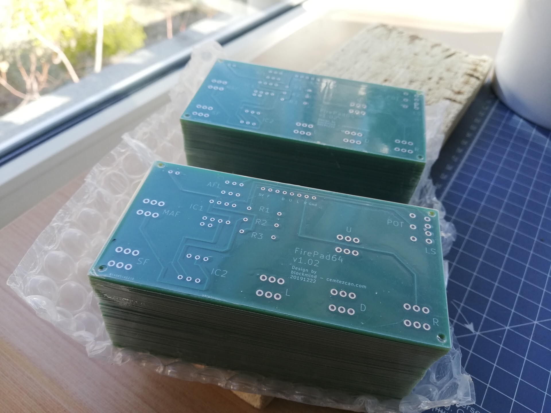
This time with the help of C64Istanbul from PCBway, I got a keyboard replacement PCB where you can also order by this link:
https://www.pcbway.com/project/shareproject/COMMODORE_64_USB_KEYBOARD_FOR_BMC64_Poor_man_s_Keyrah_89d5c4fc.html

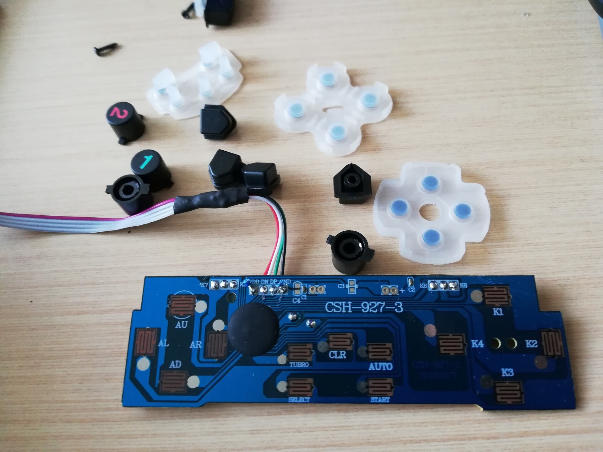
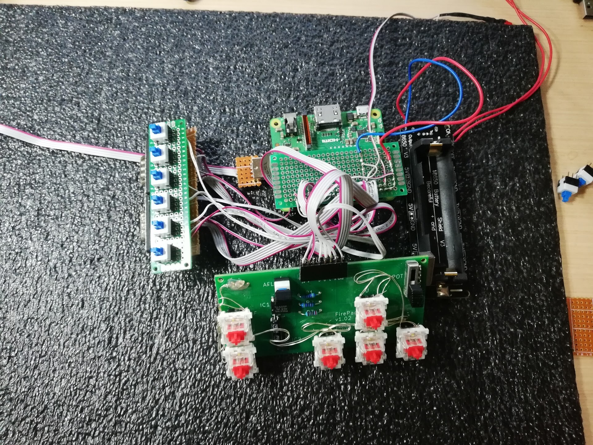
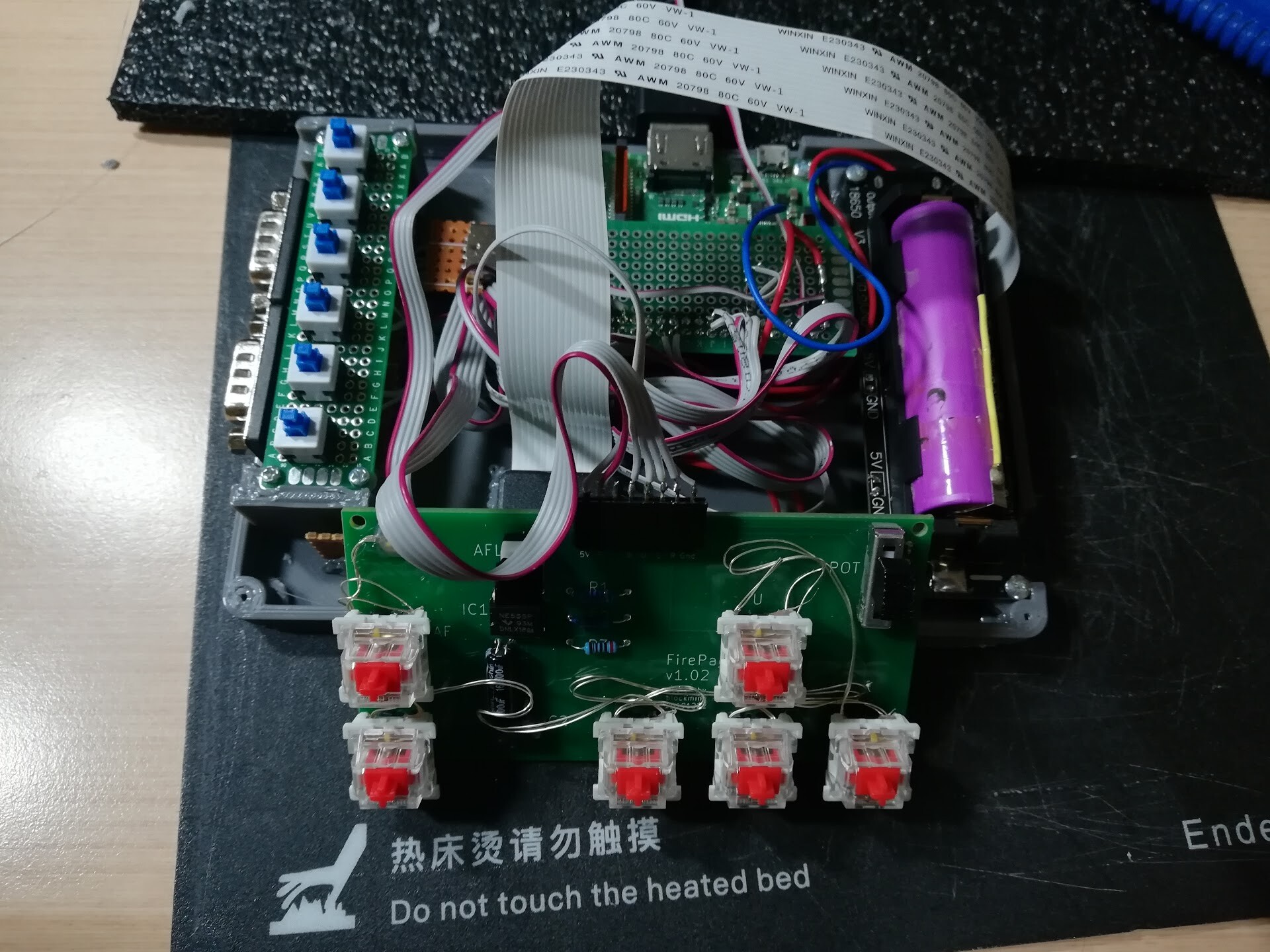
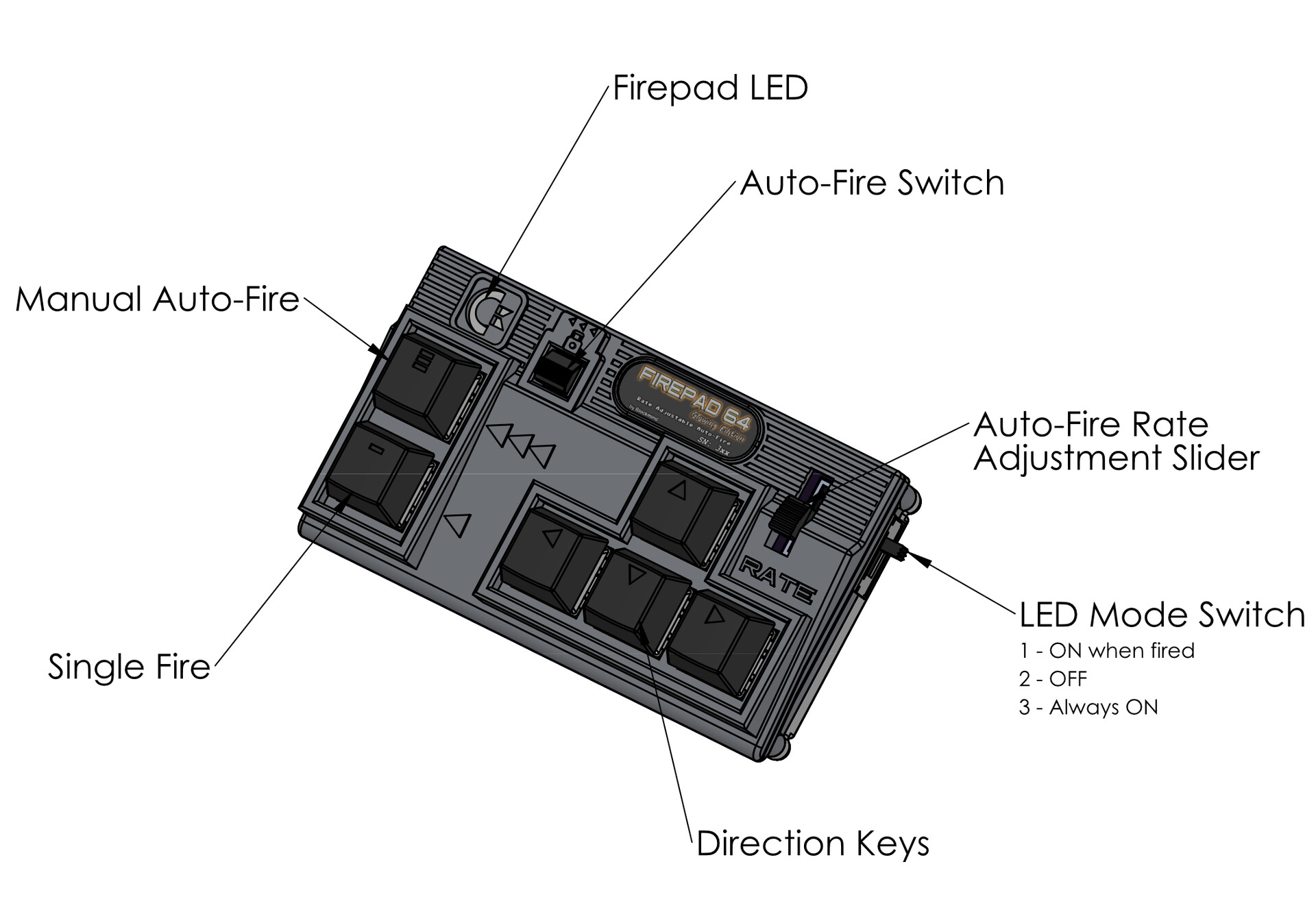
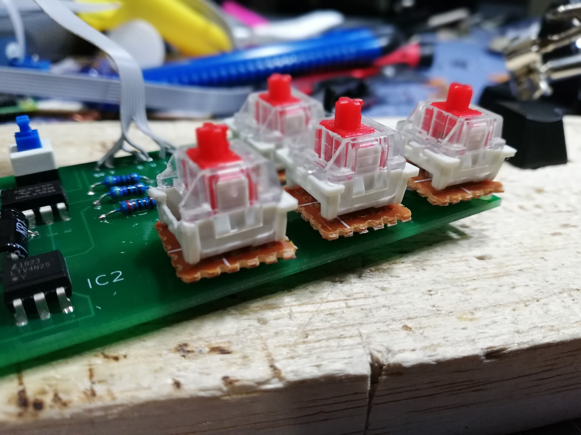
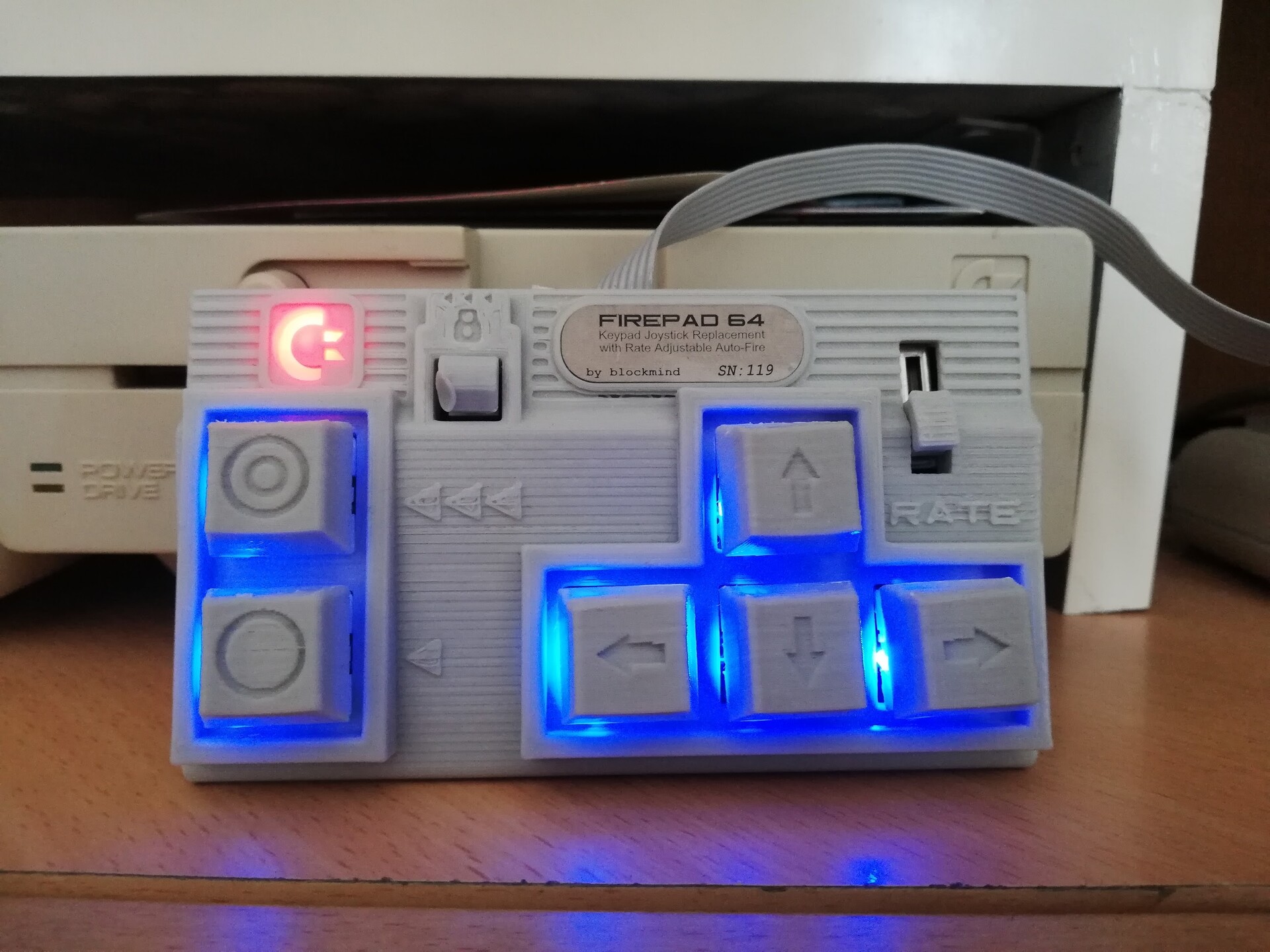
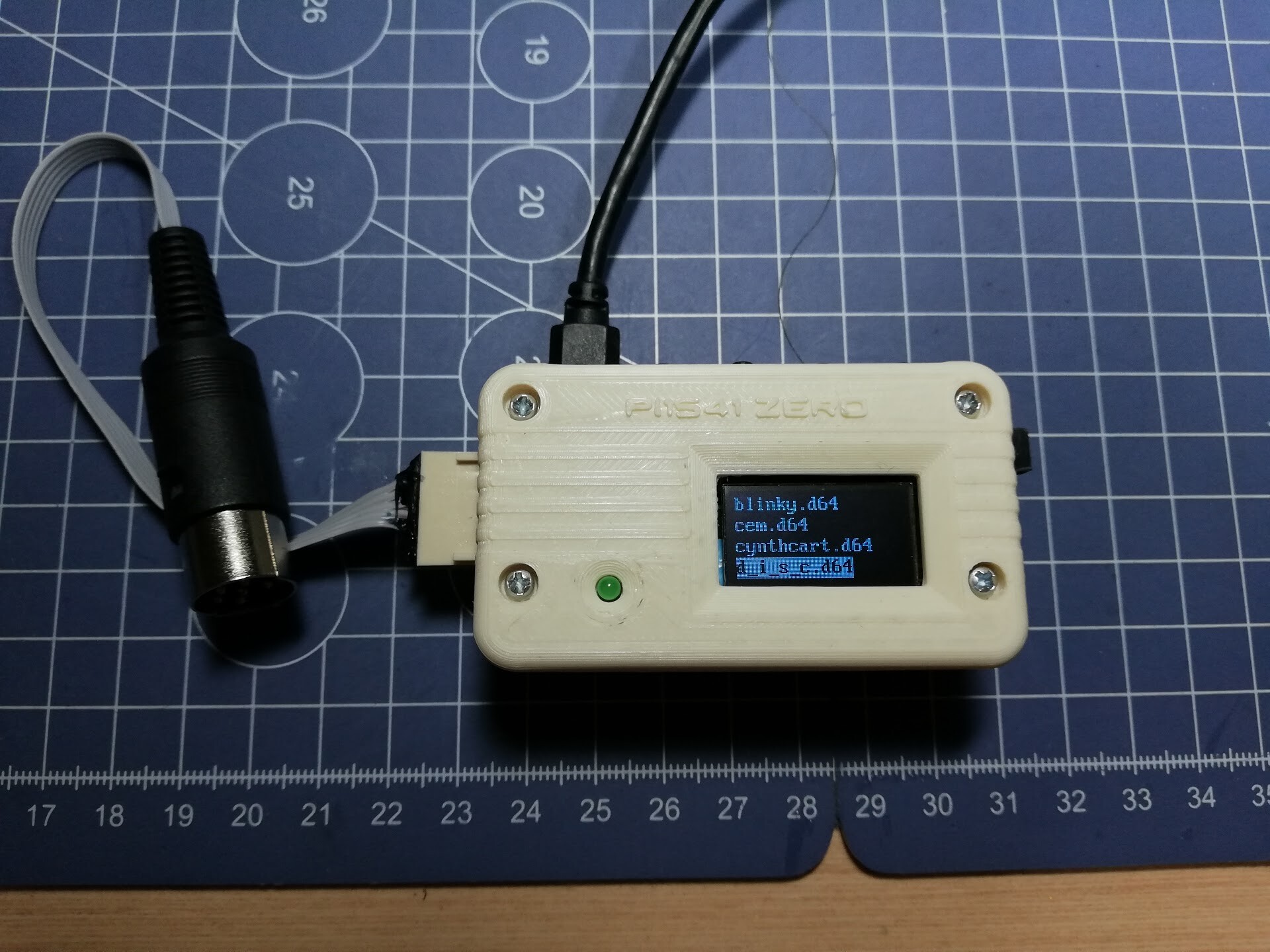
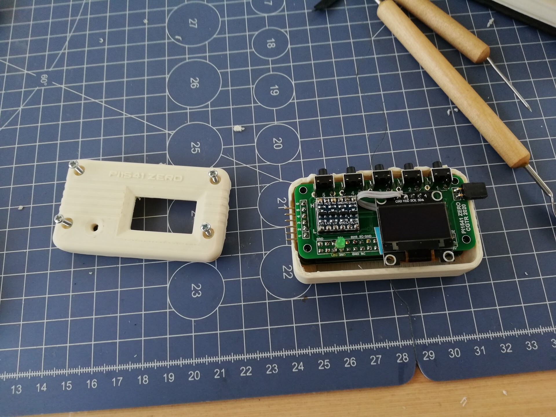
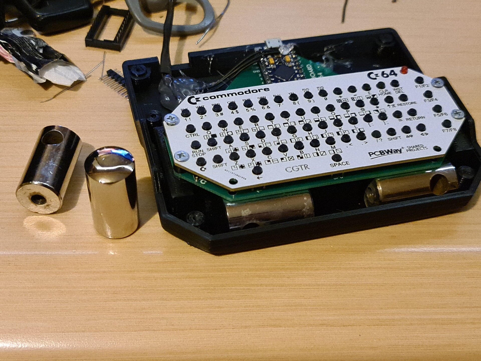
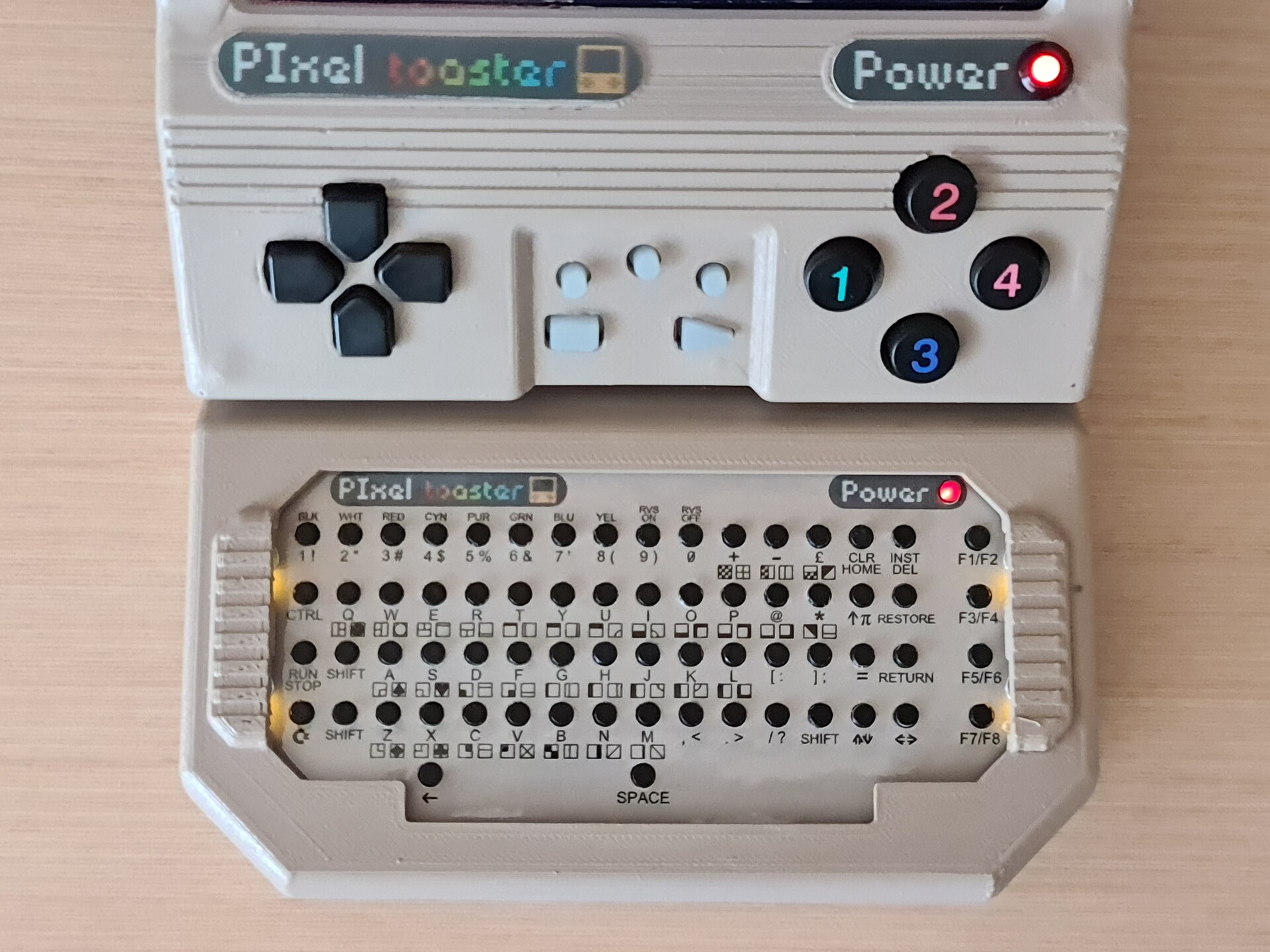
This keyboard has the exact mapping with a real C64 keyboard so the emulators recognize it %100 compatible. It uses an Arduino Pro Micro to make it reconized by a USB interface on the Raspberry PI or PC devices.

image courtasy C64iSTANBUL

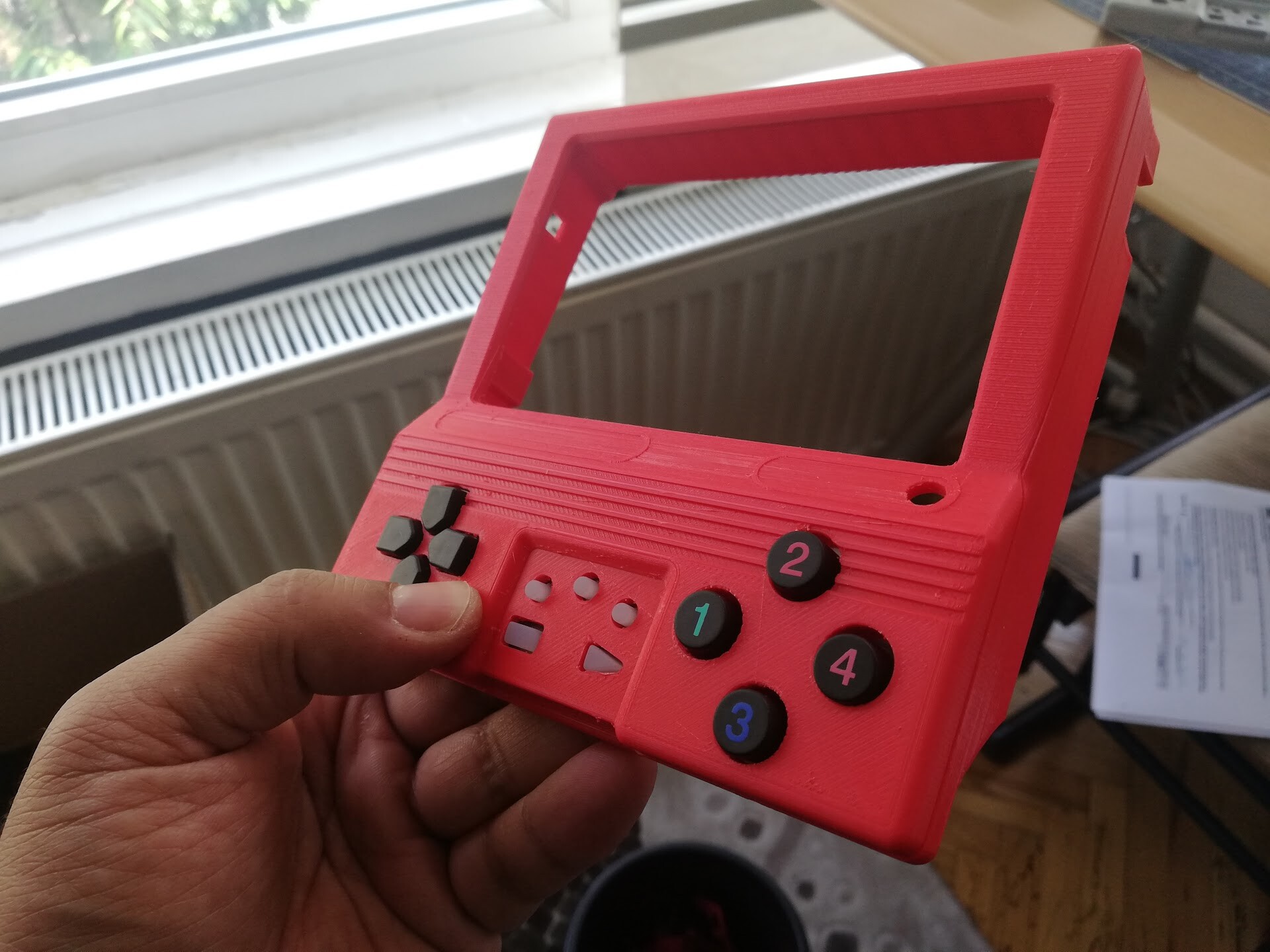
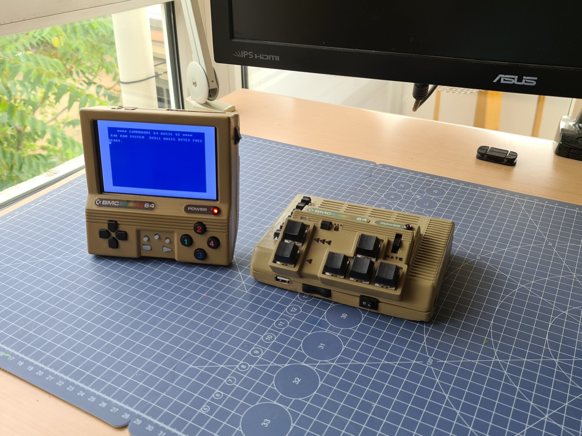
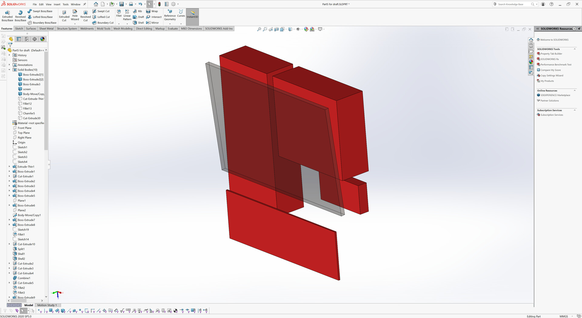
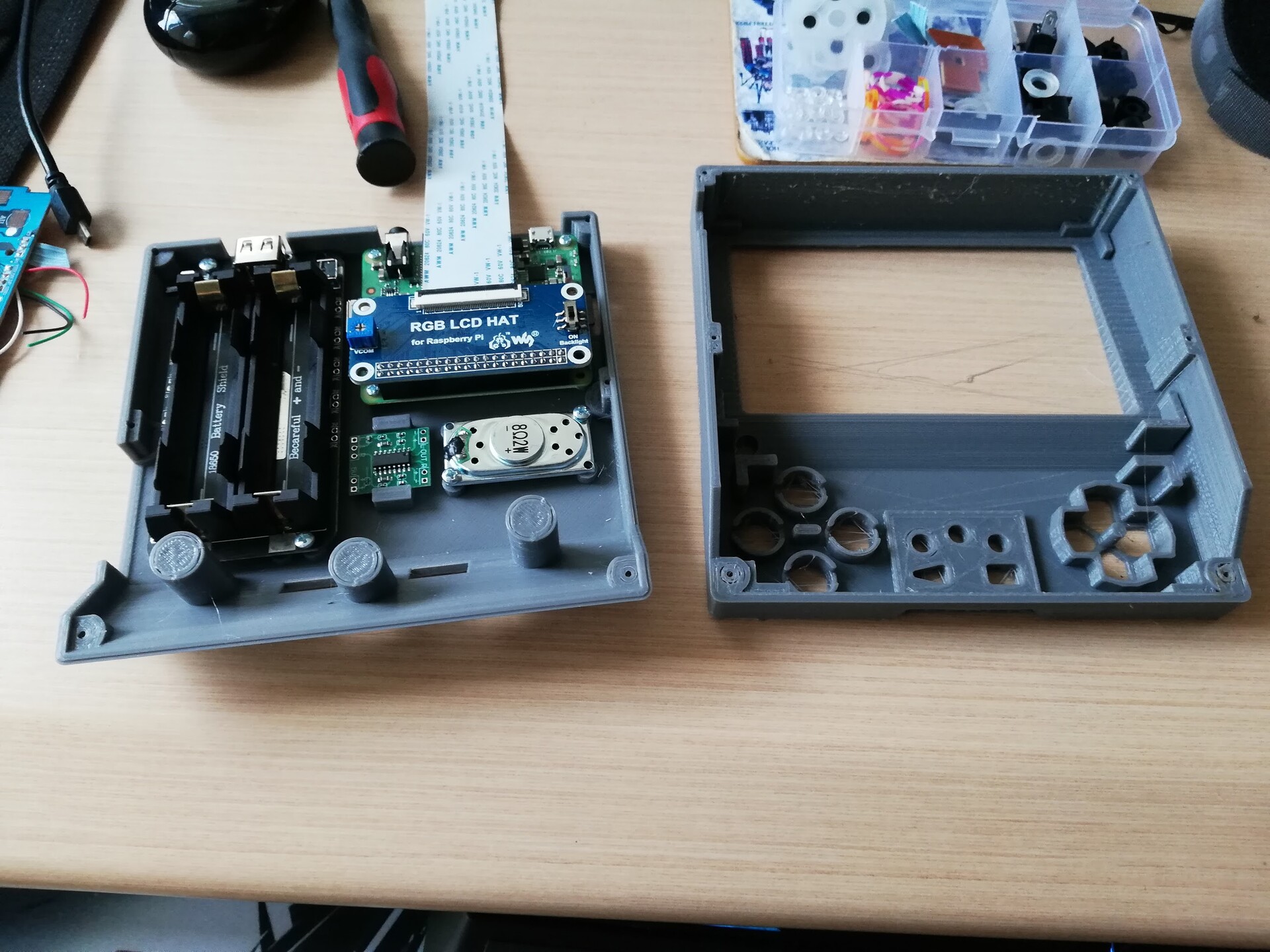
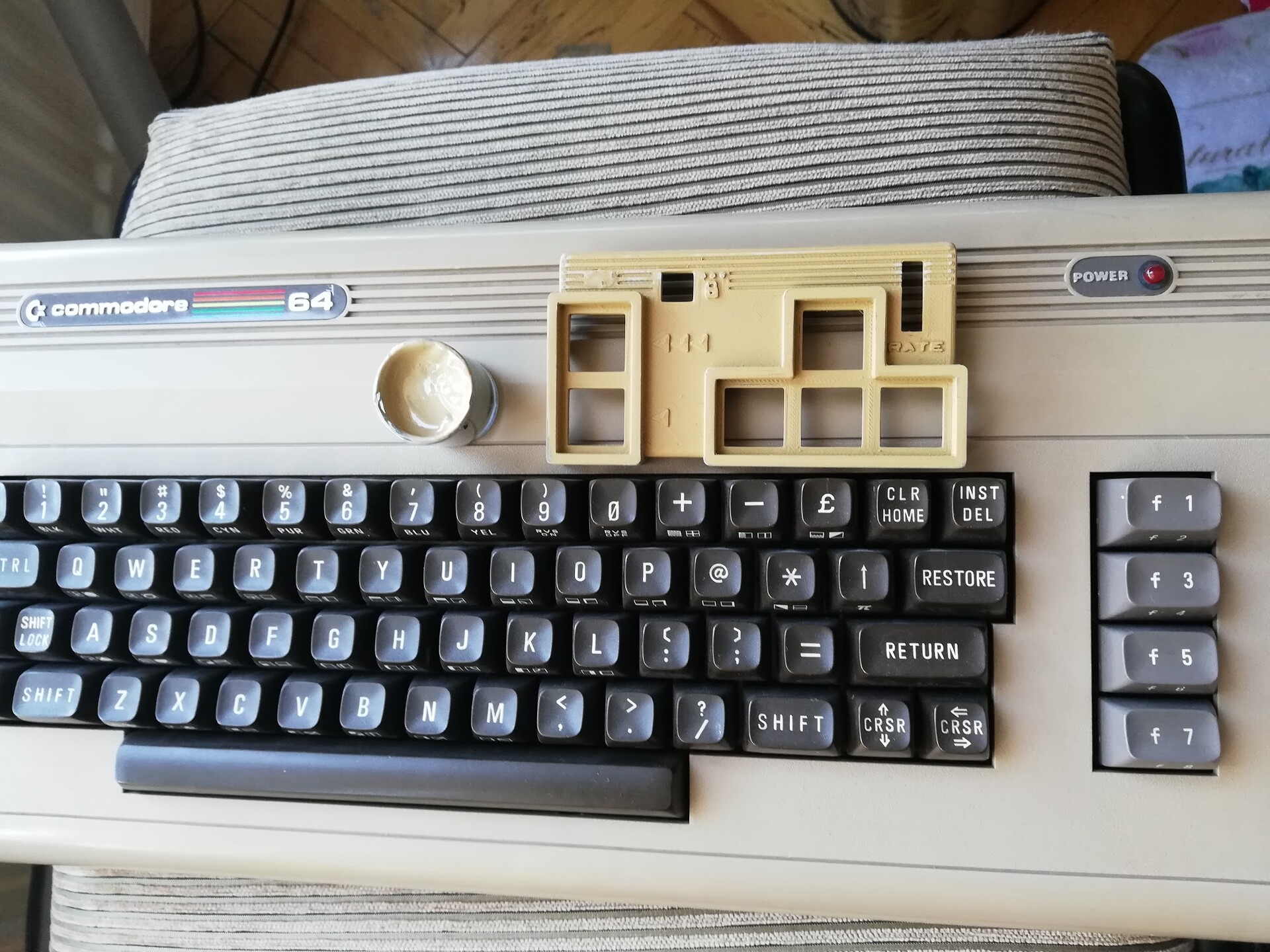
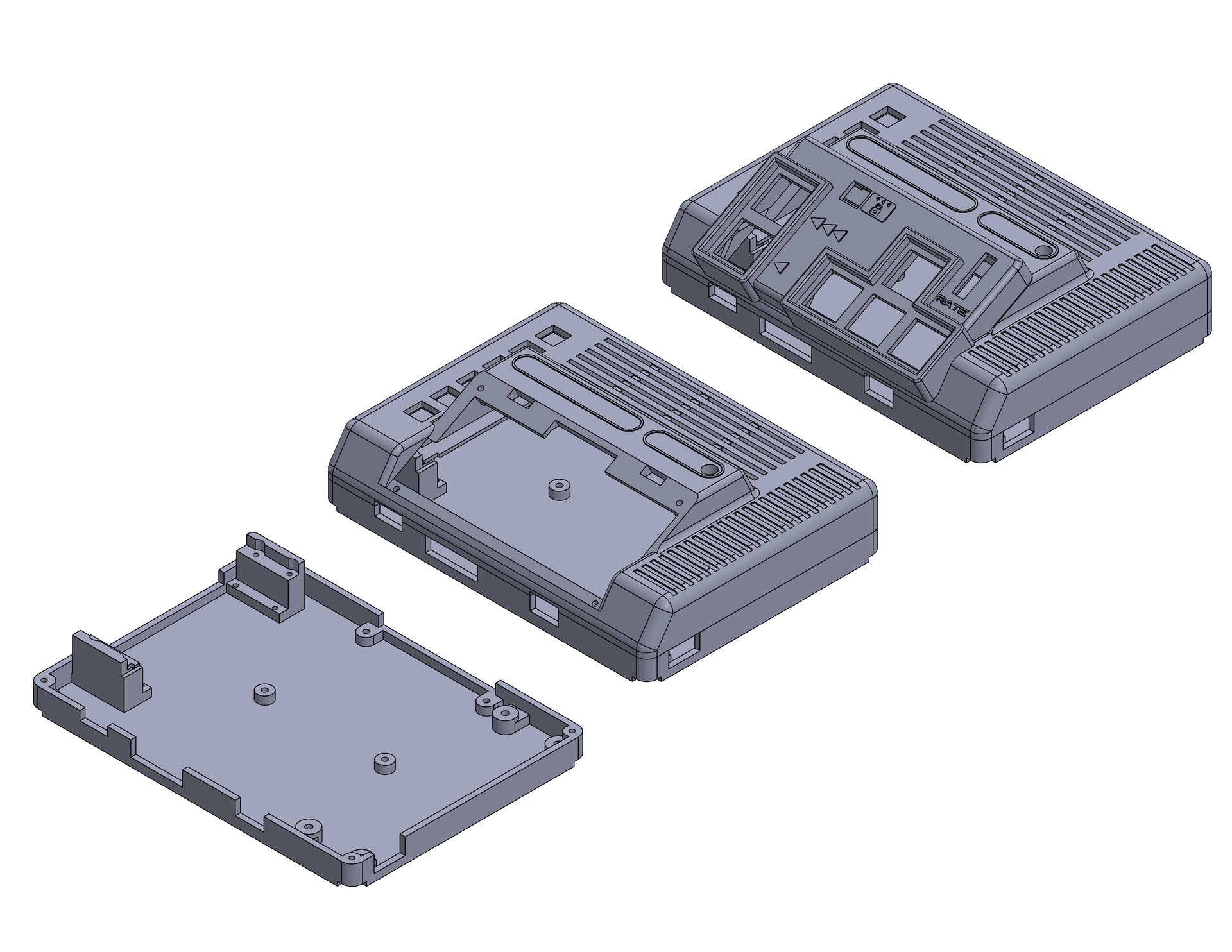
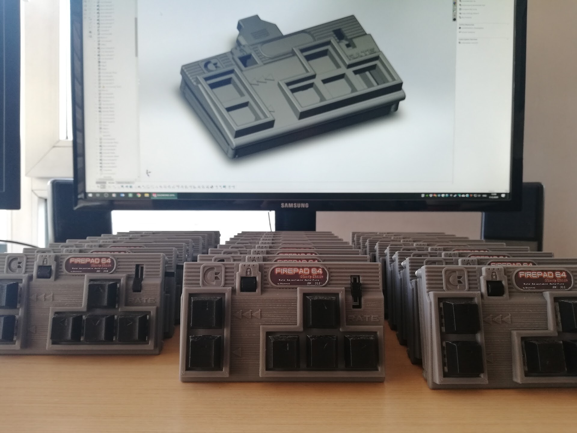
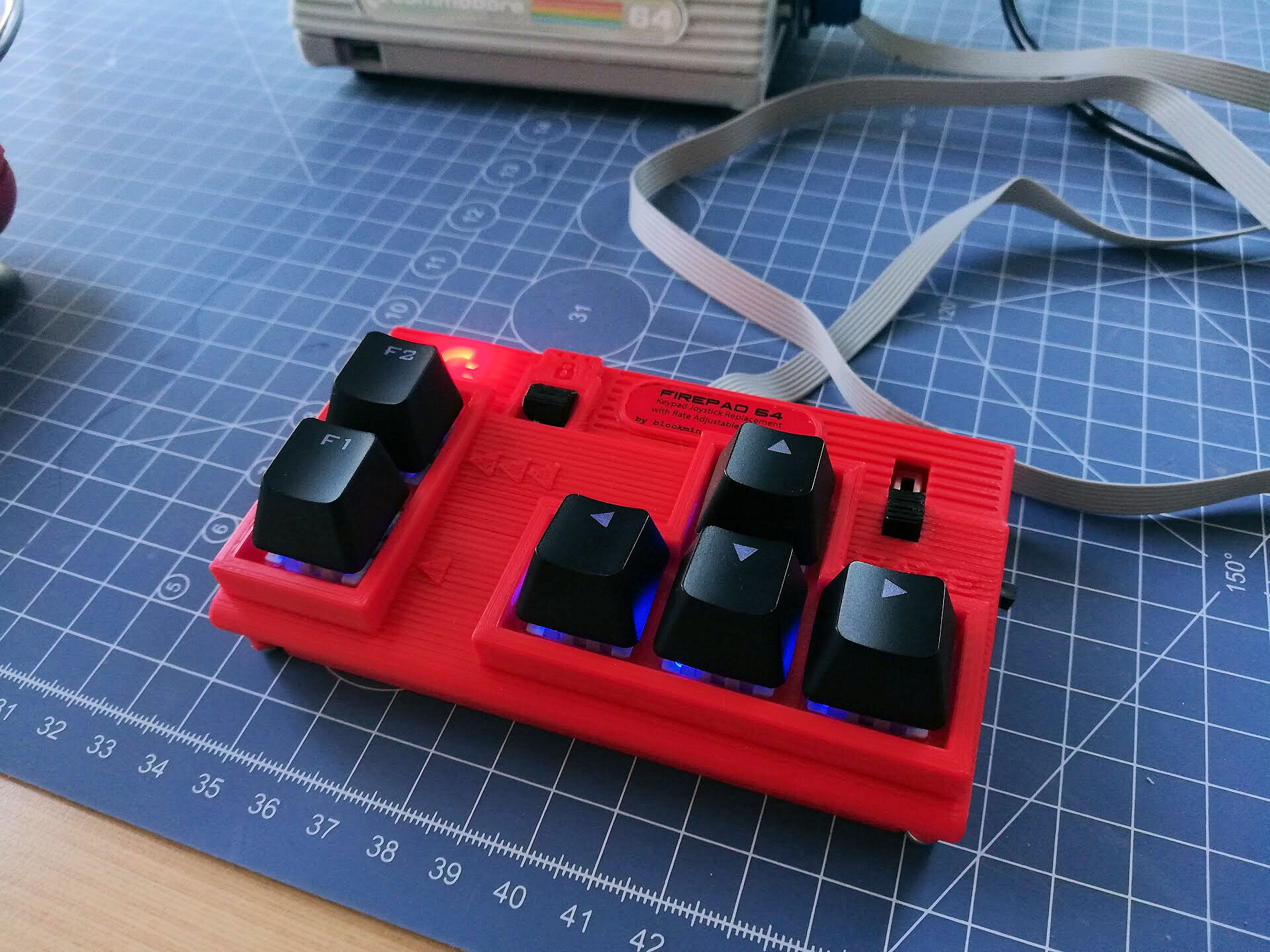
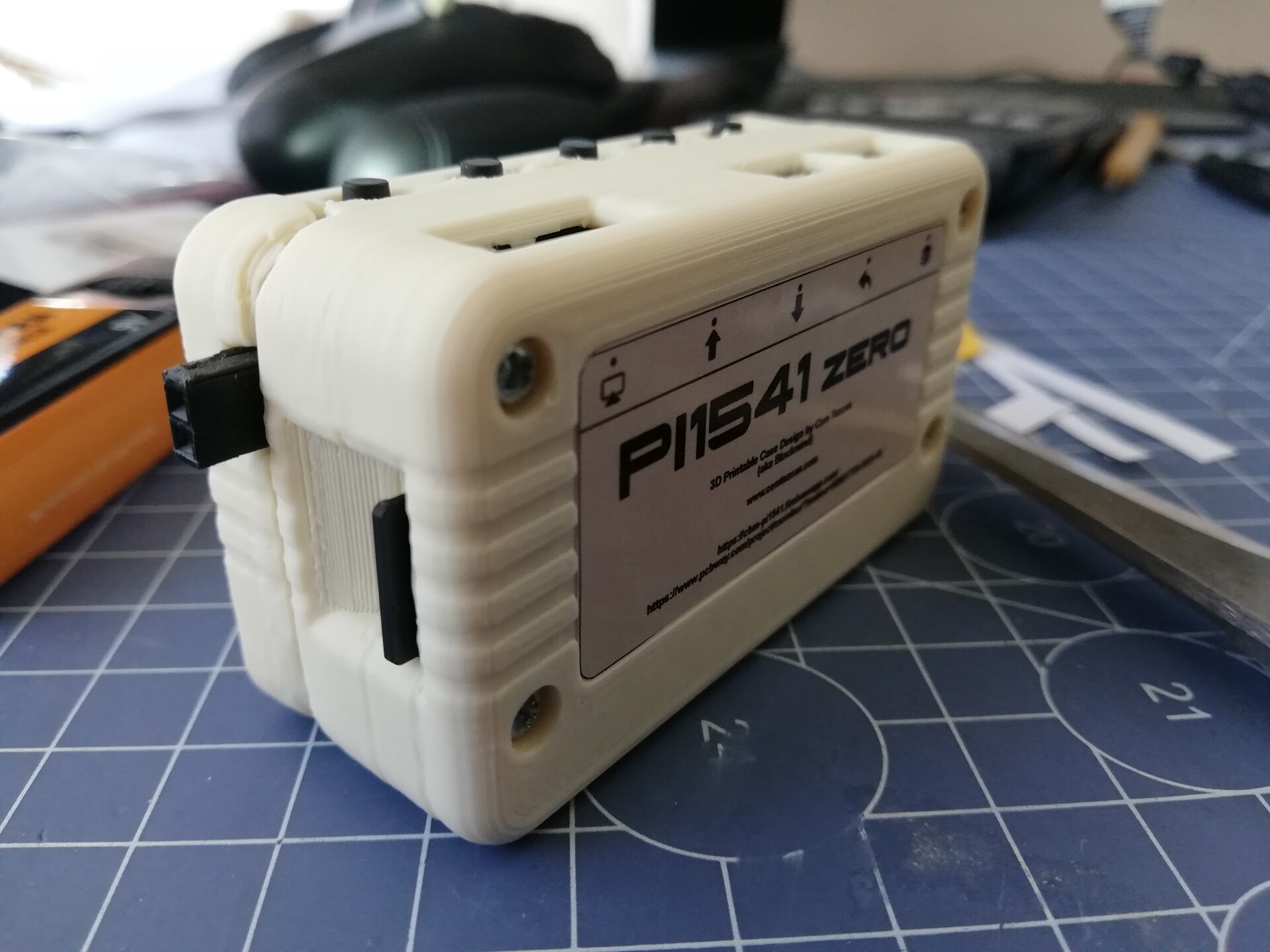
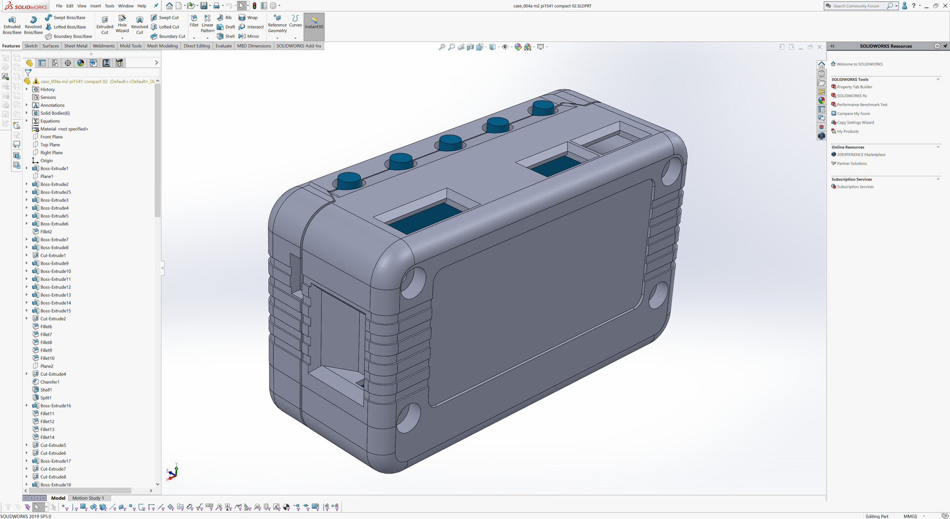
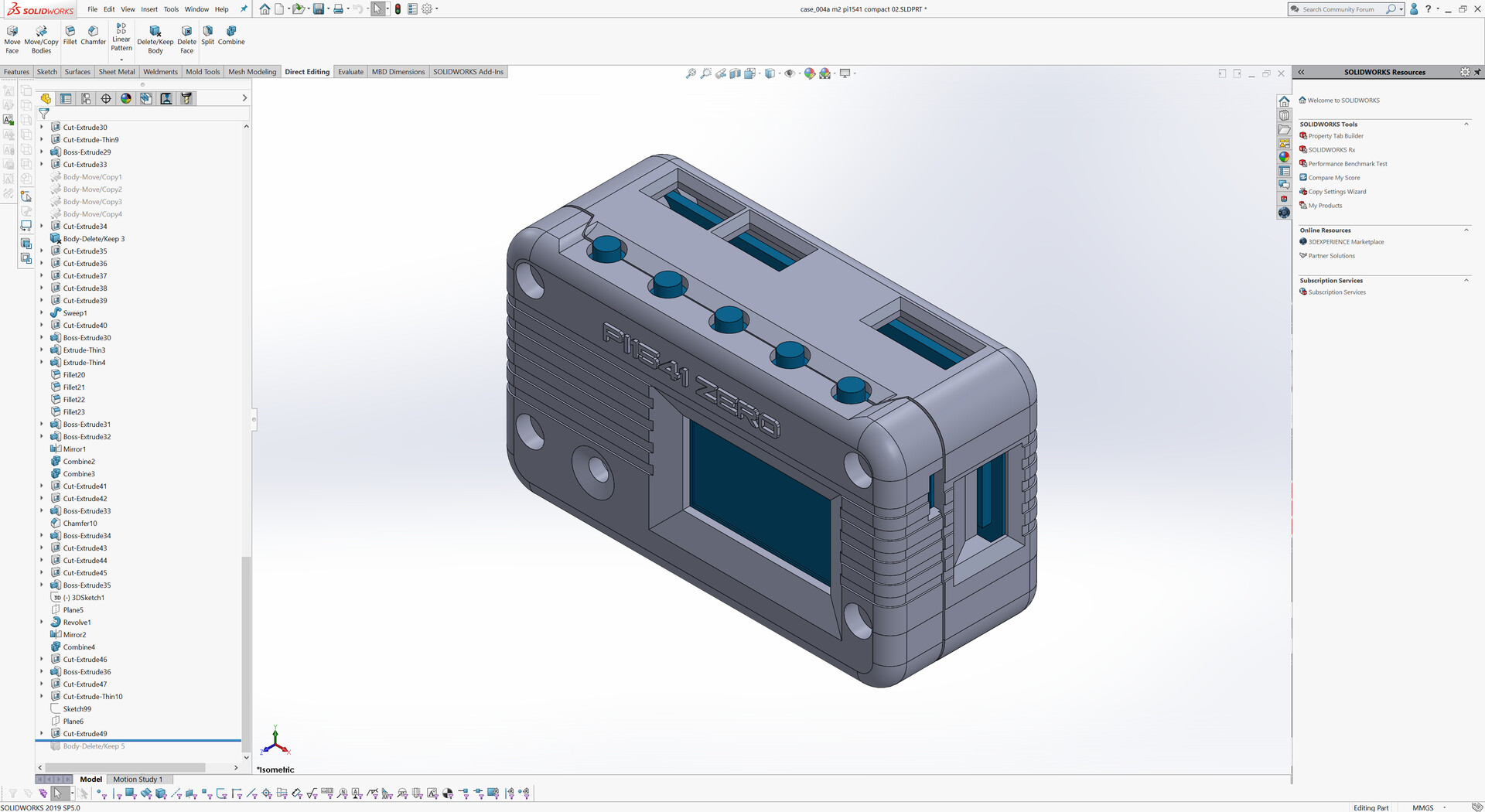
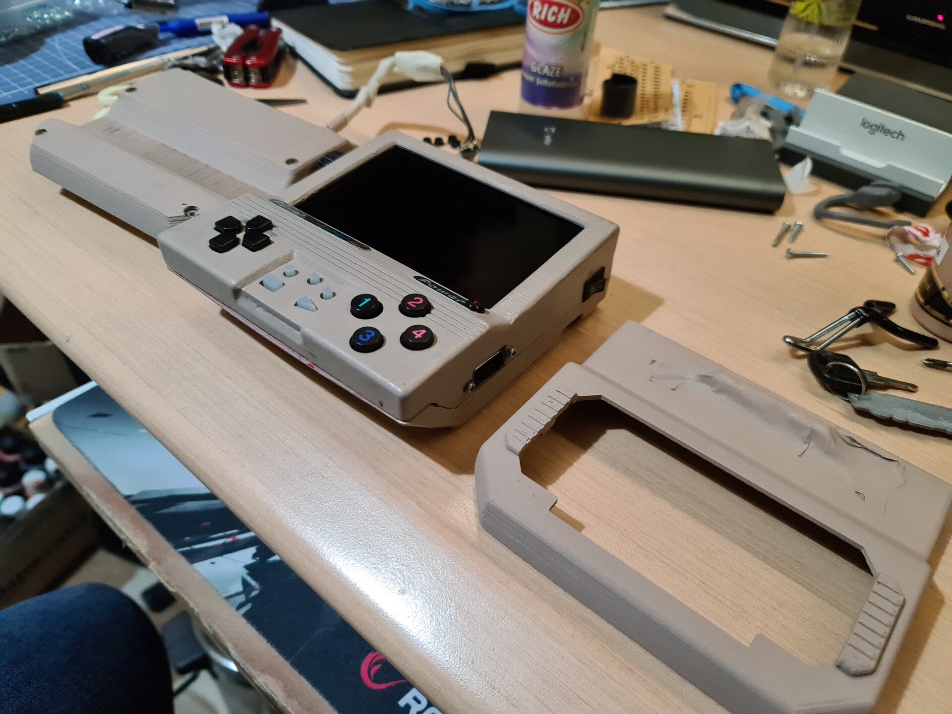
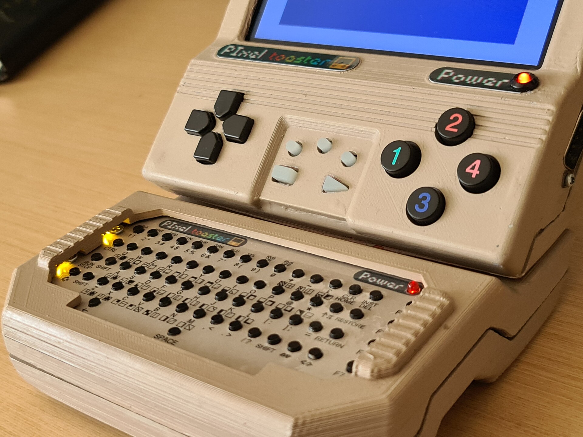
So by having this keyboard PCB, I decided to make an expansion module for my handheld console. Normally I have a stand for the device to put it on surface vertically.

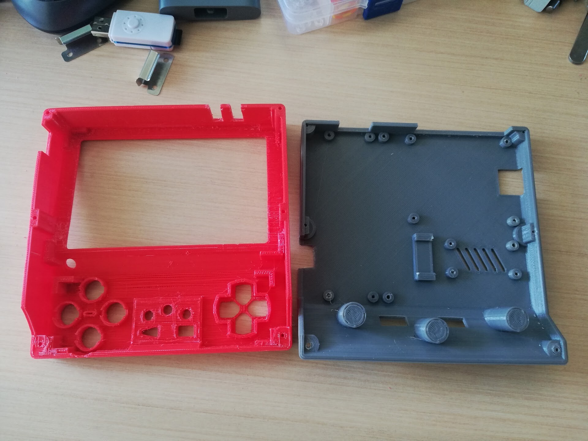
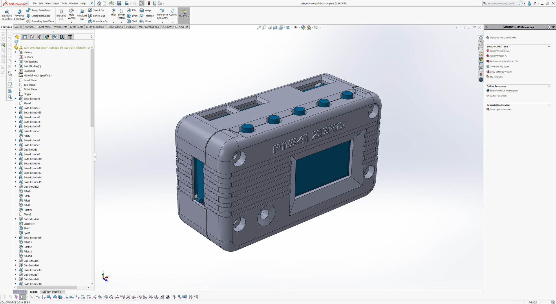
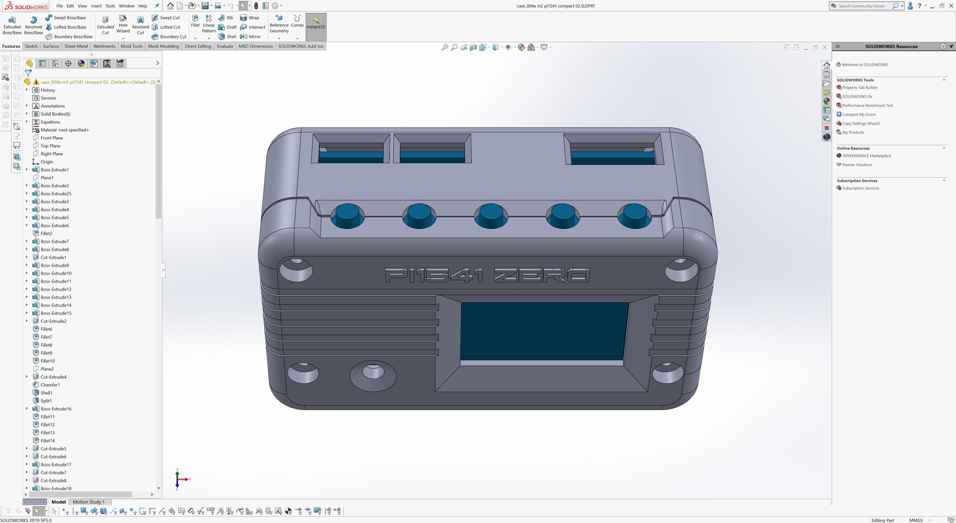
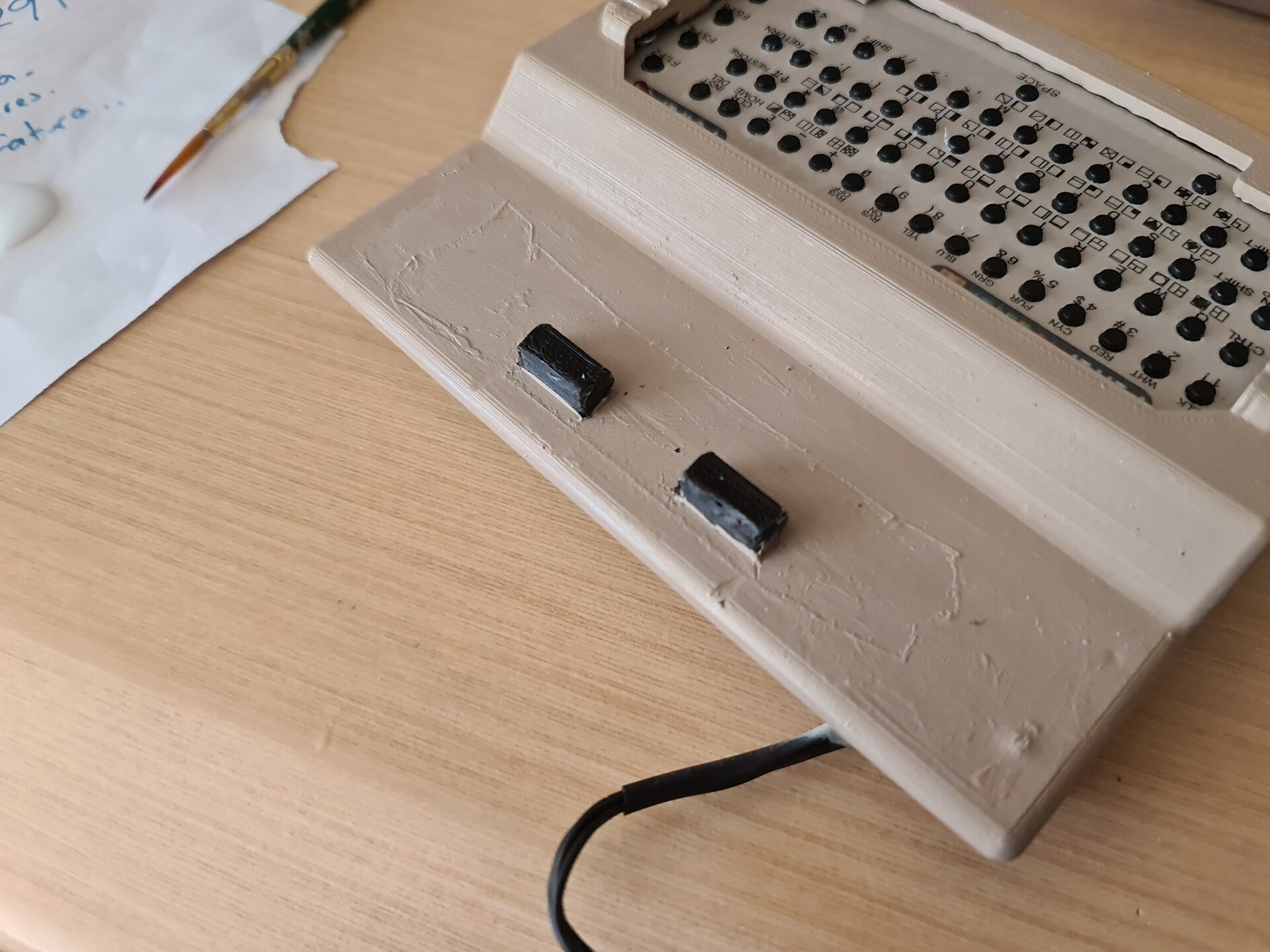
This two holes on my previous design made it possible to attach the keyboard module by here. So I completed the design according to that principle.

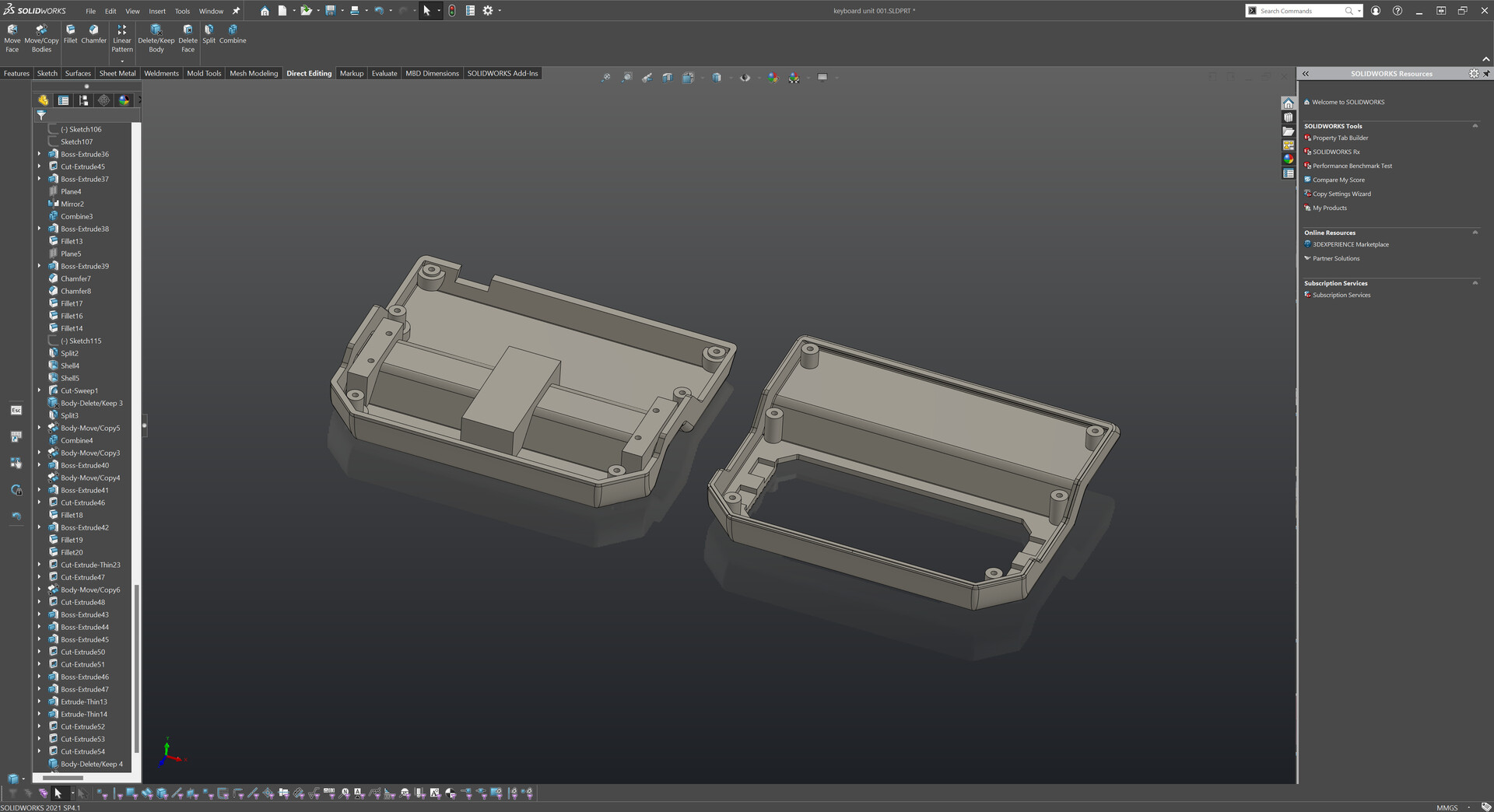
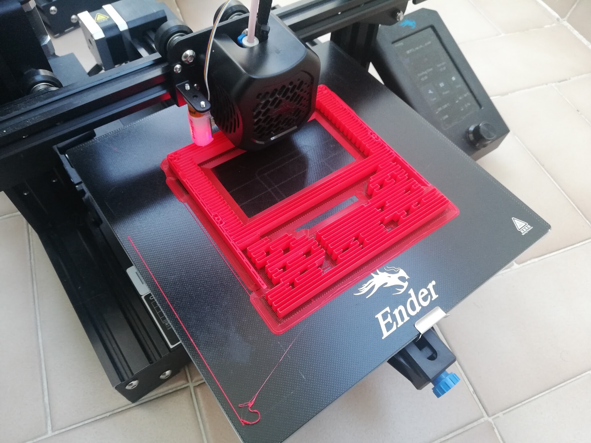
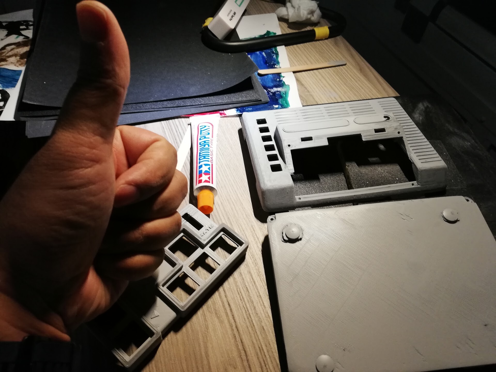
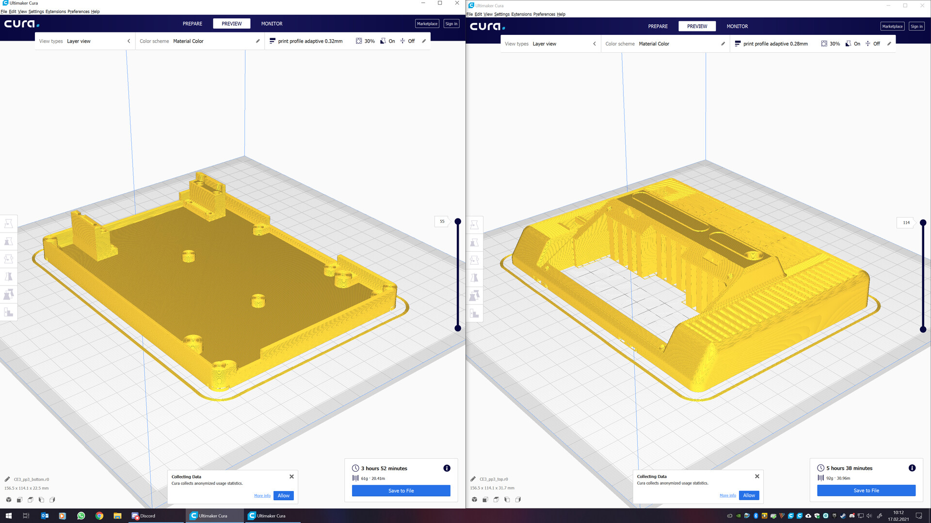
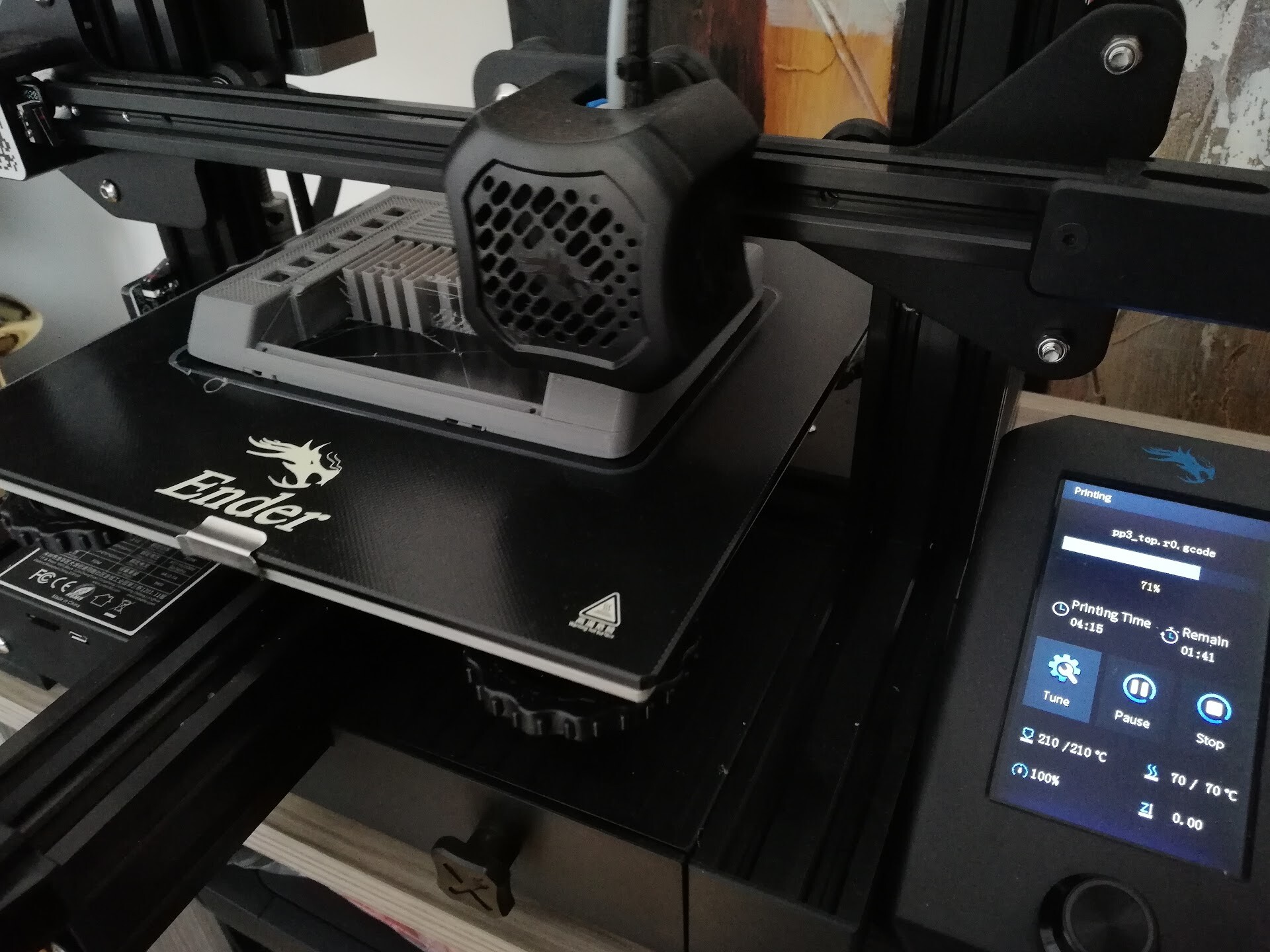
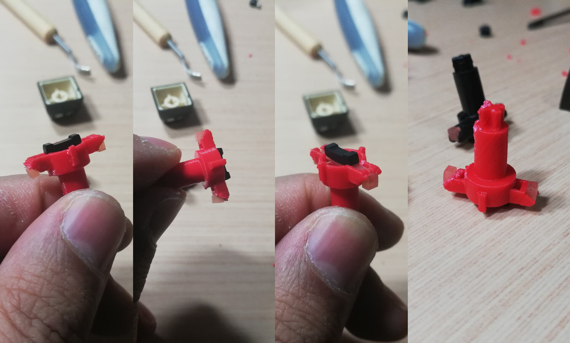
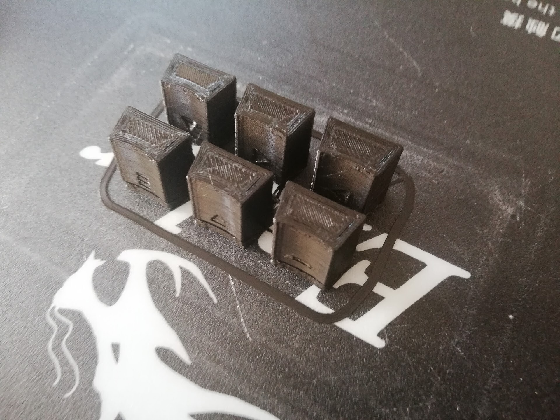
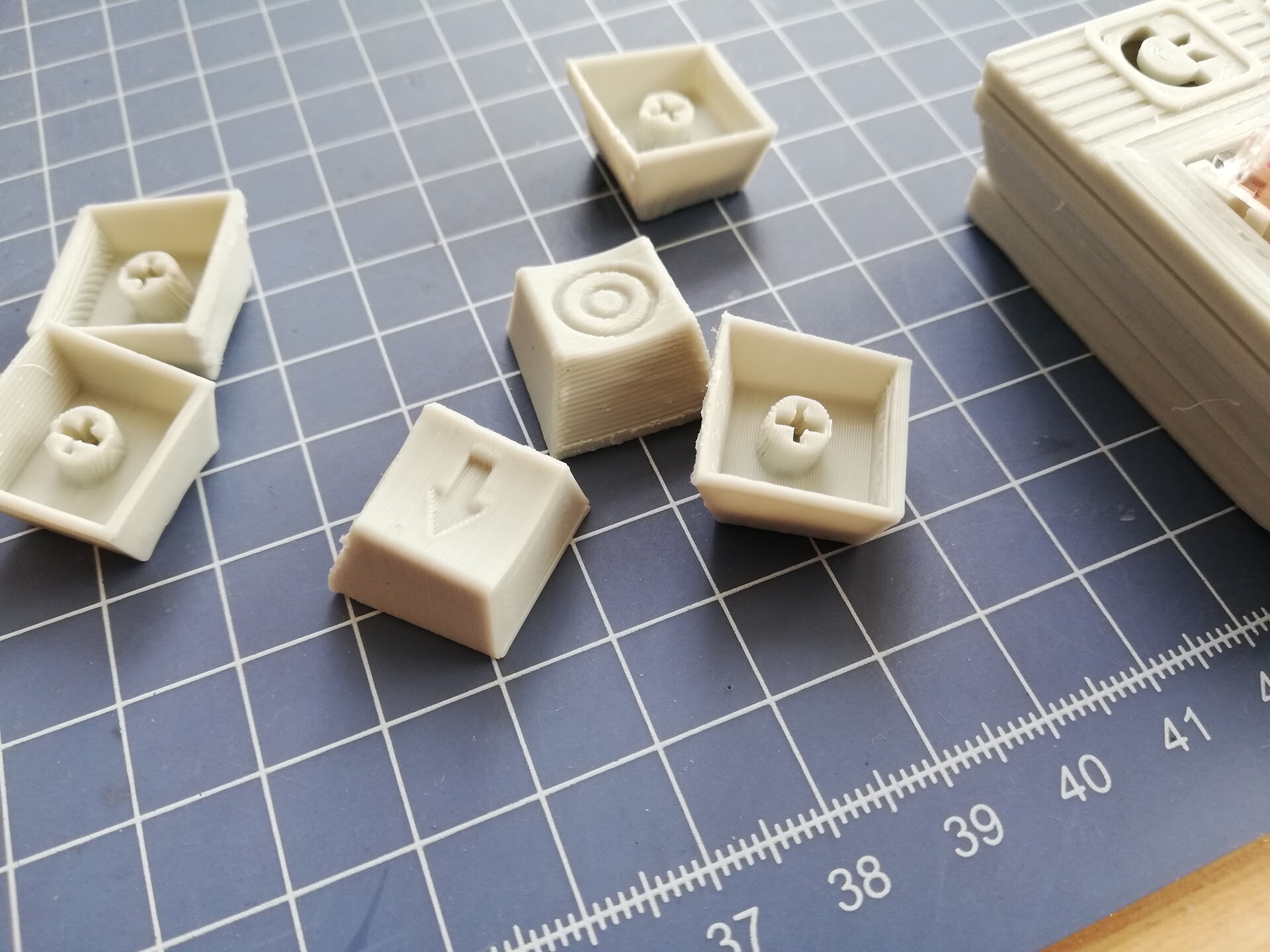
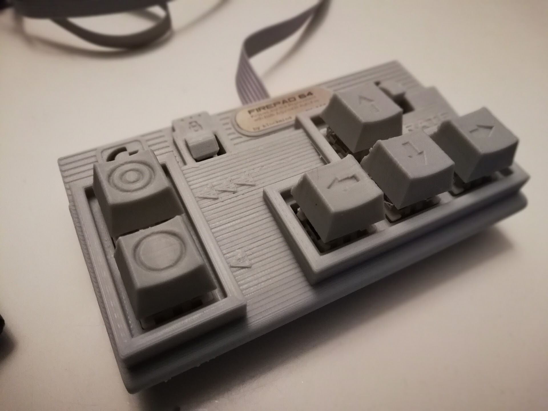
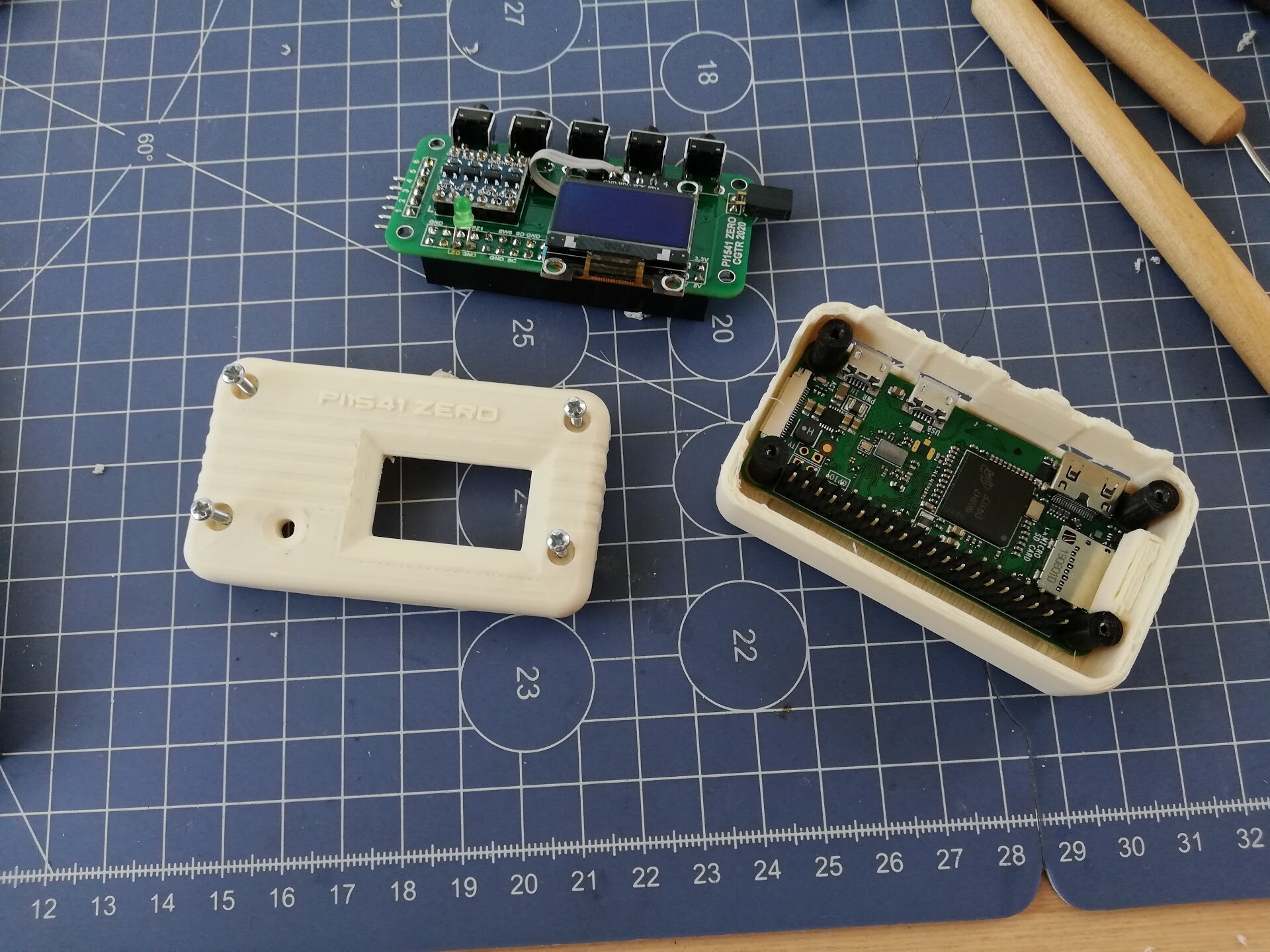
And 3d printed those with my good old Ender 3 v2.

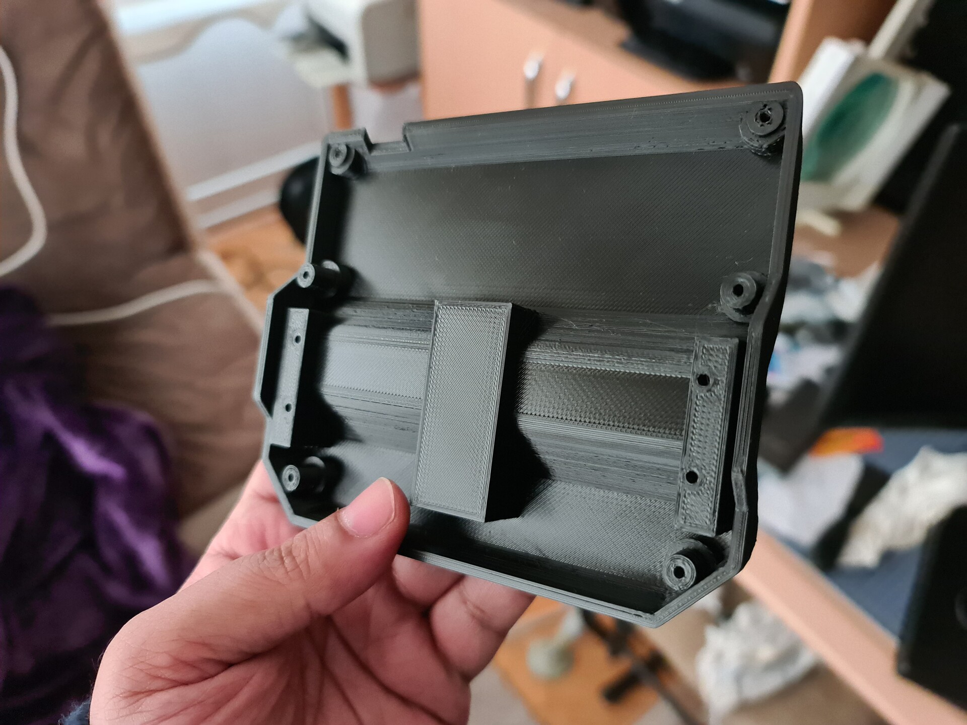
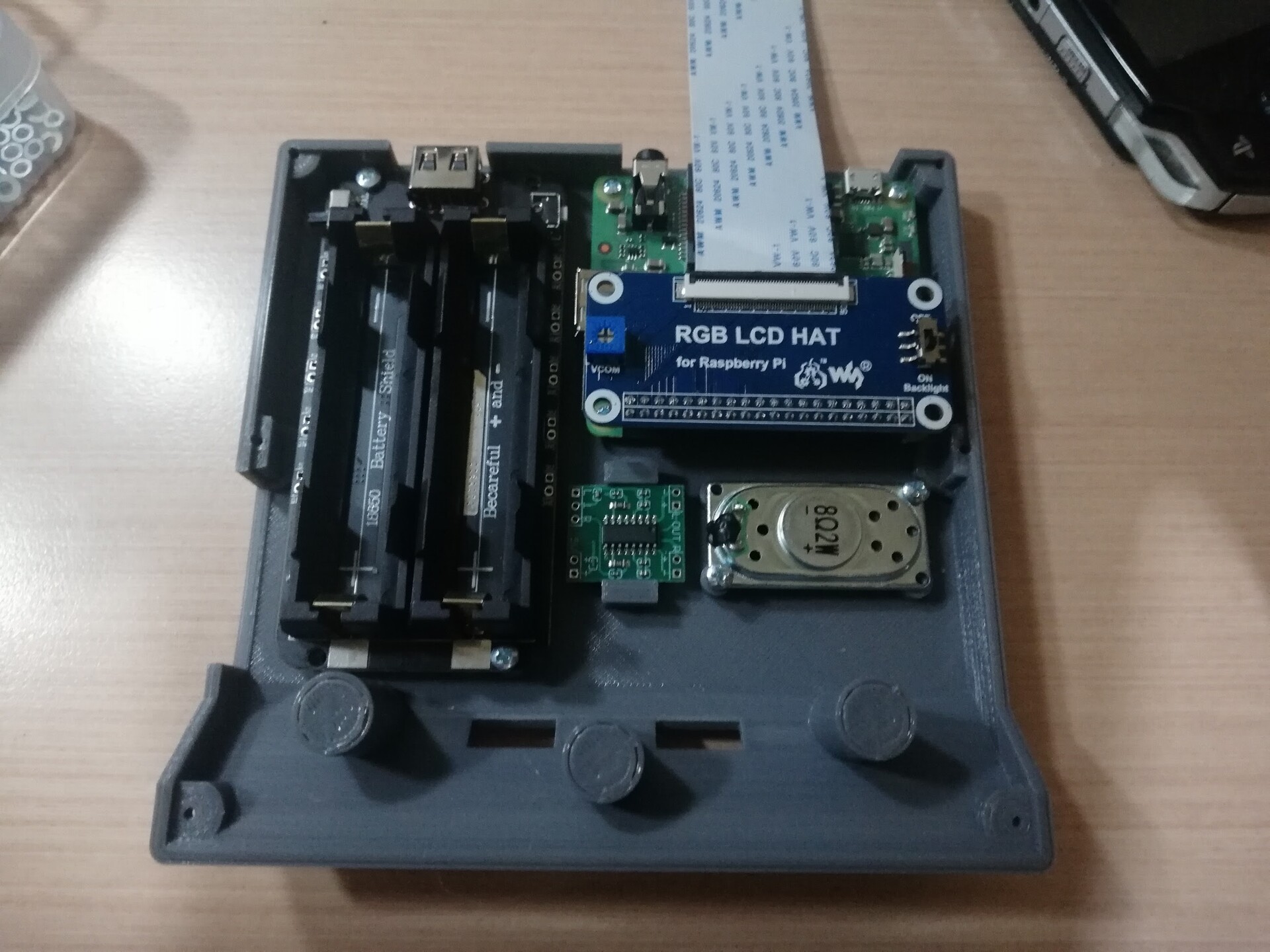
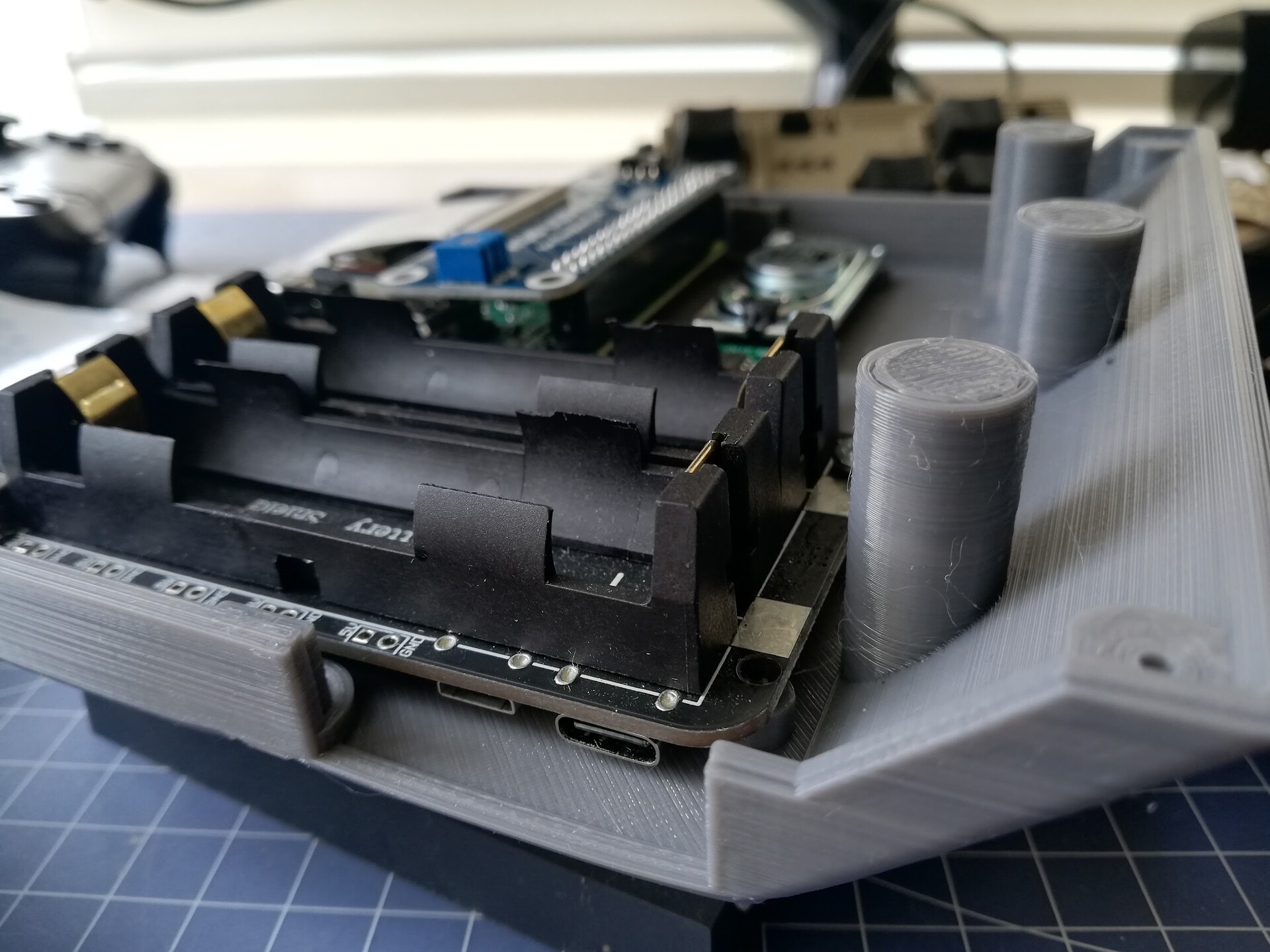
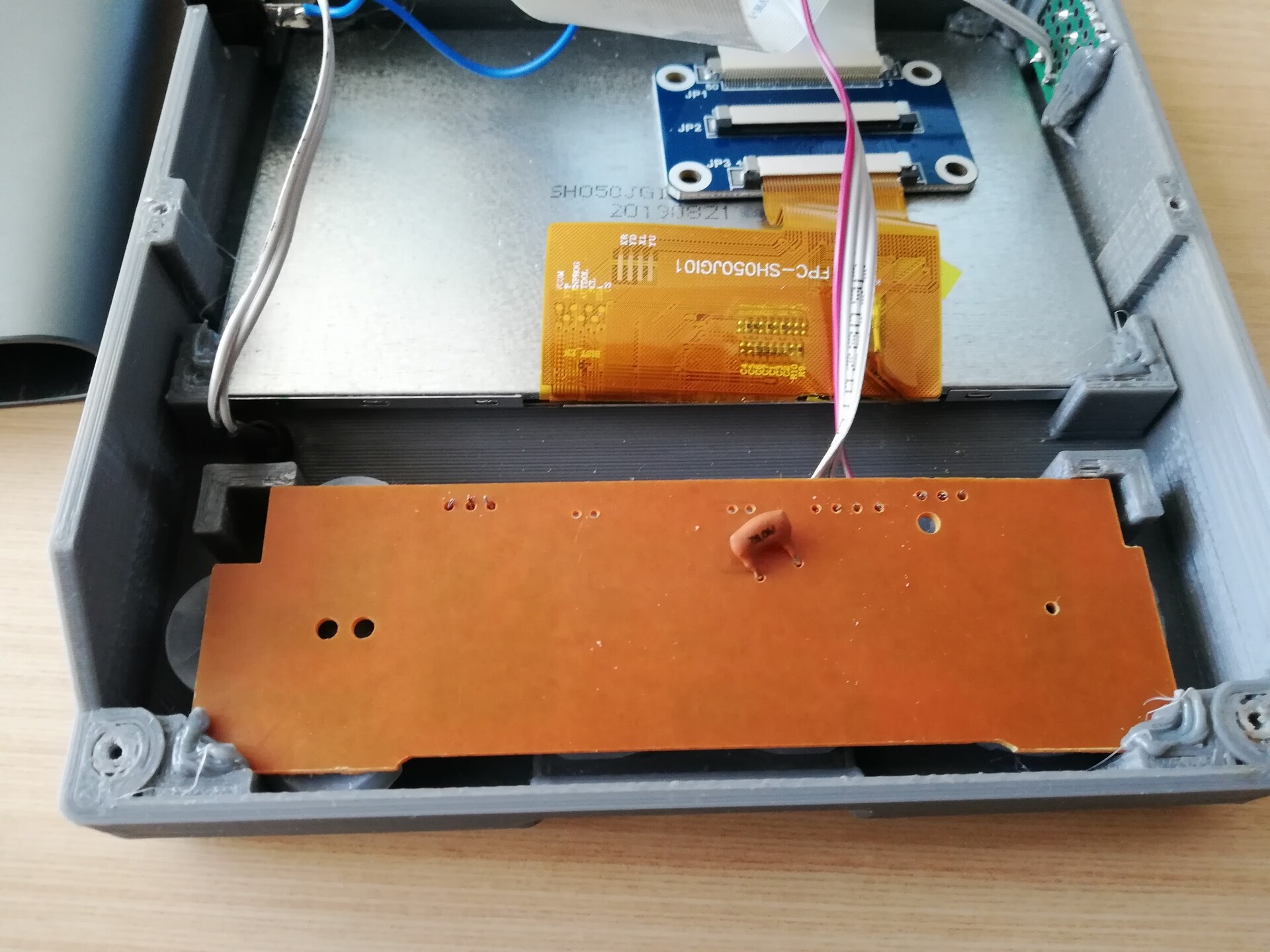
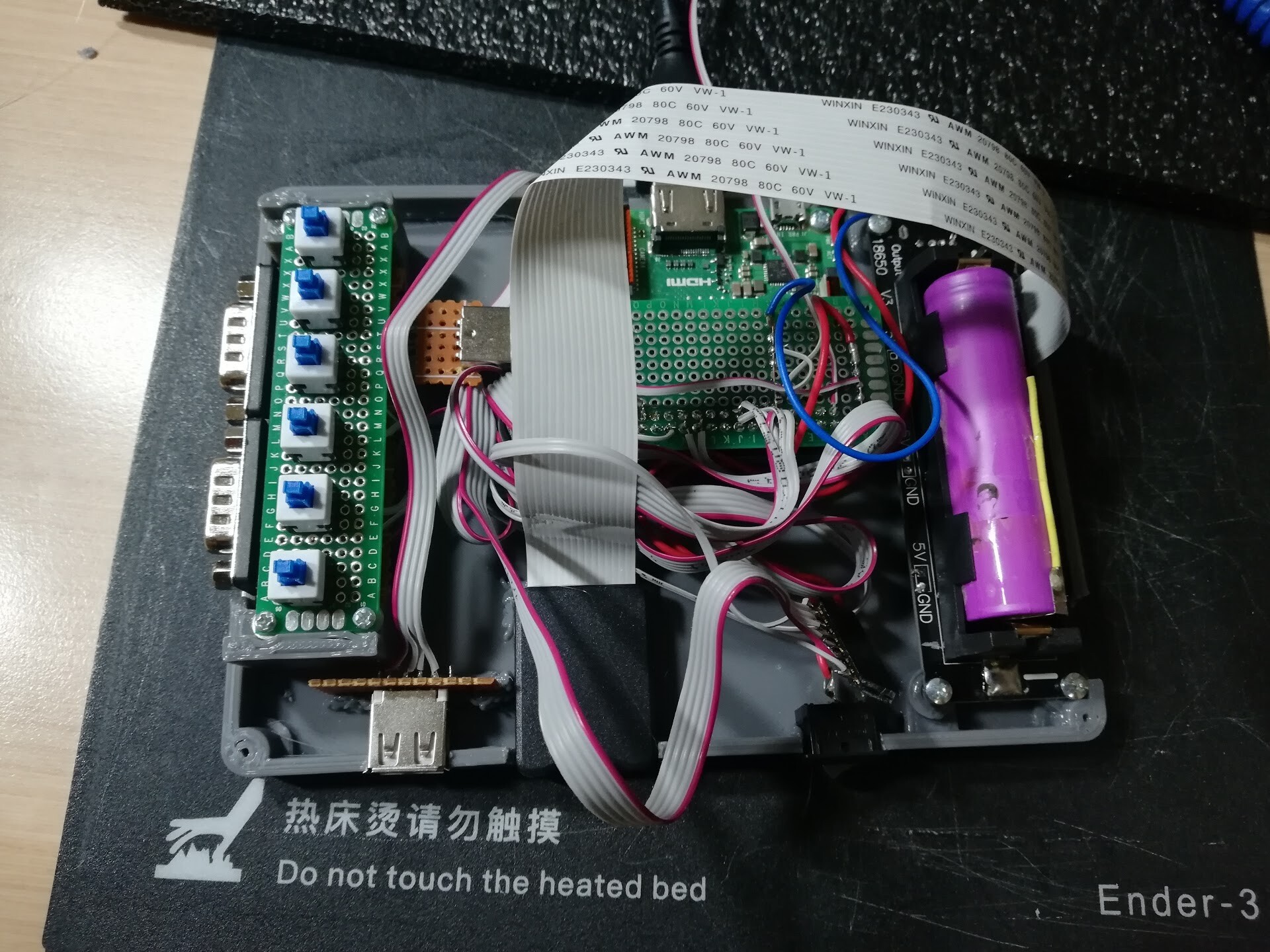
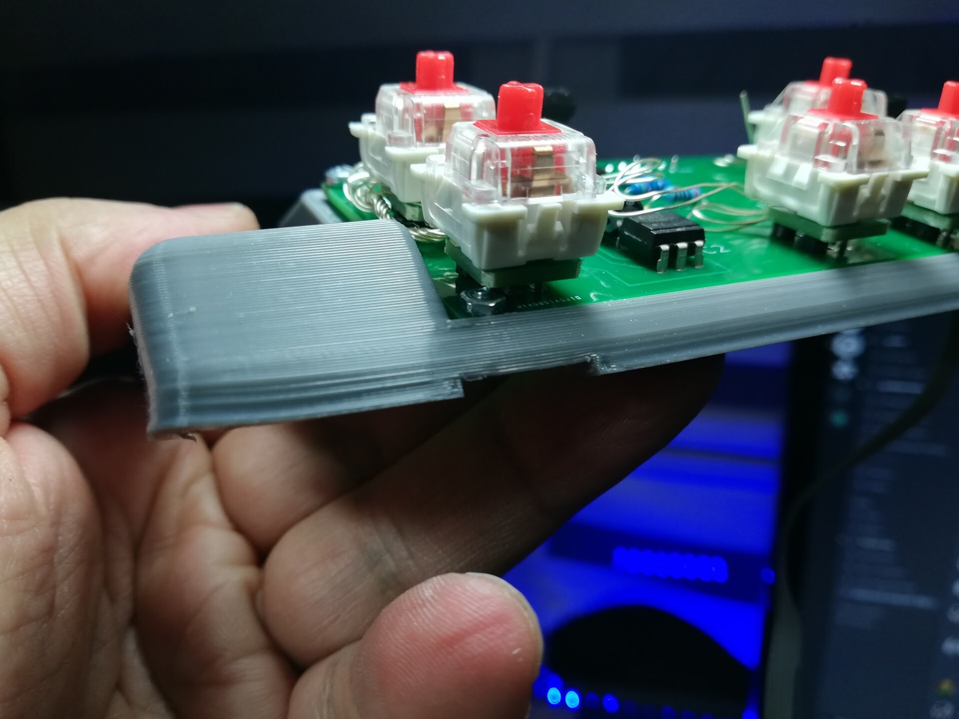
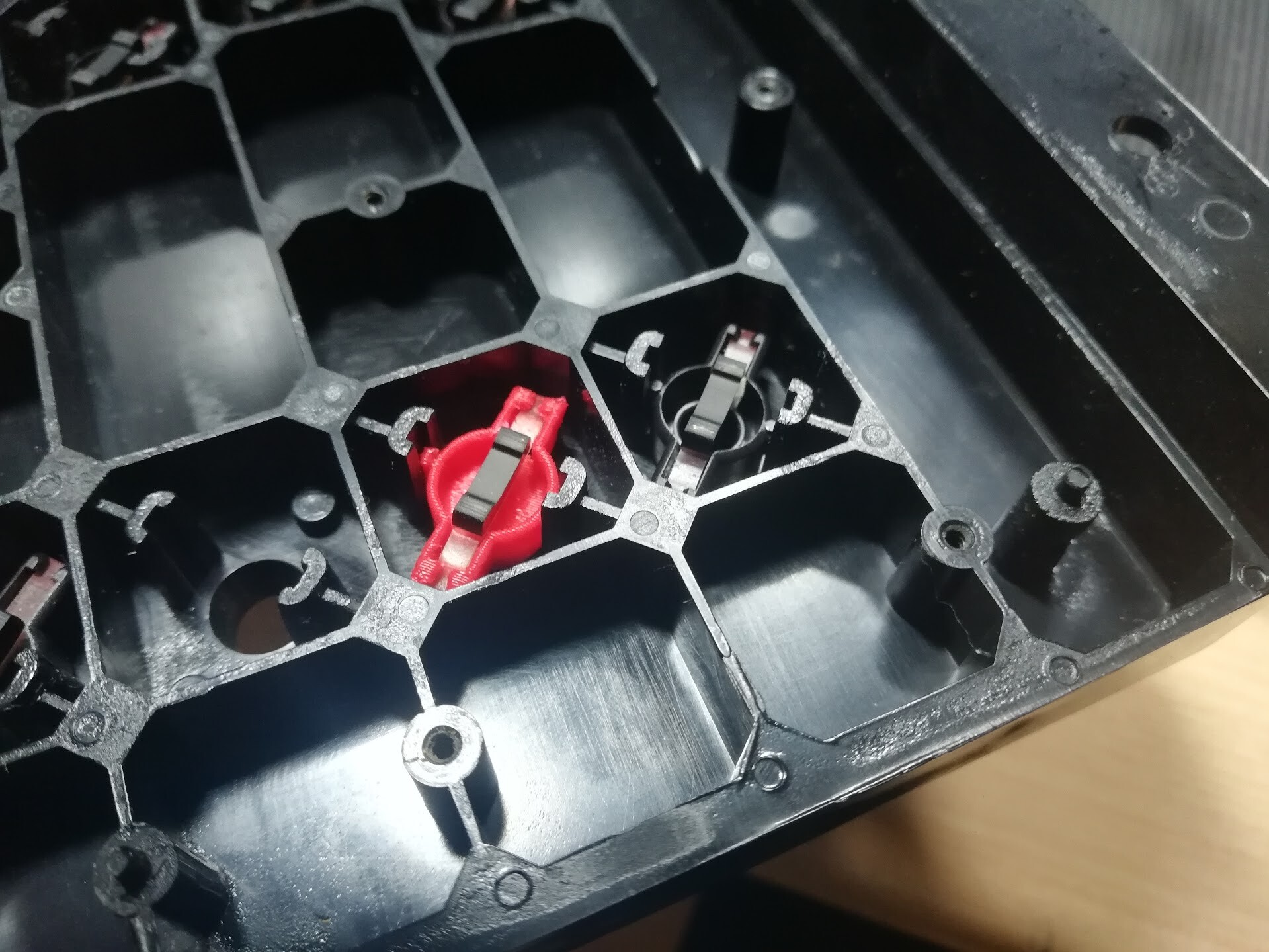
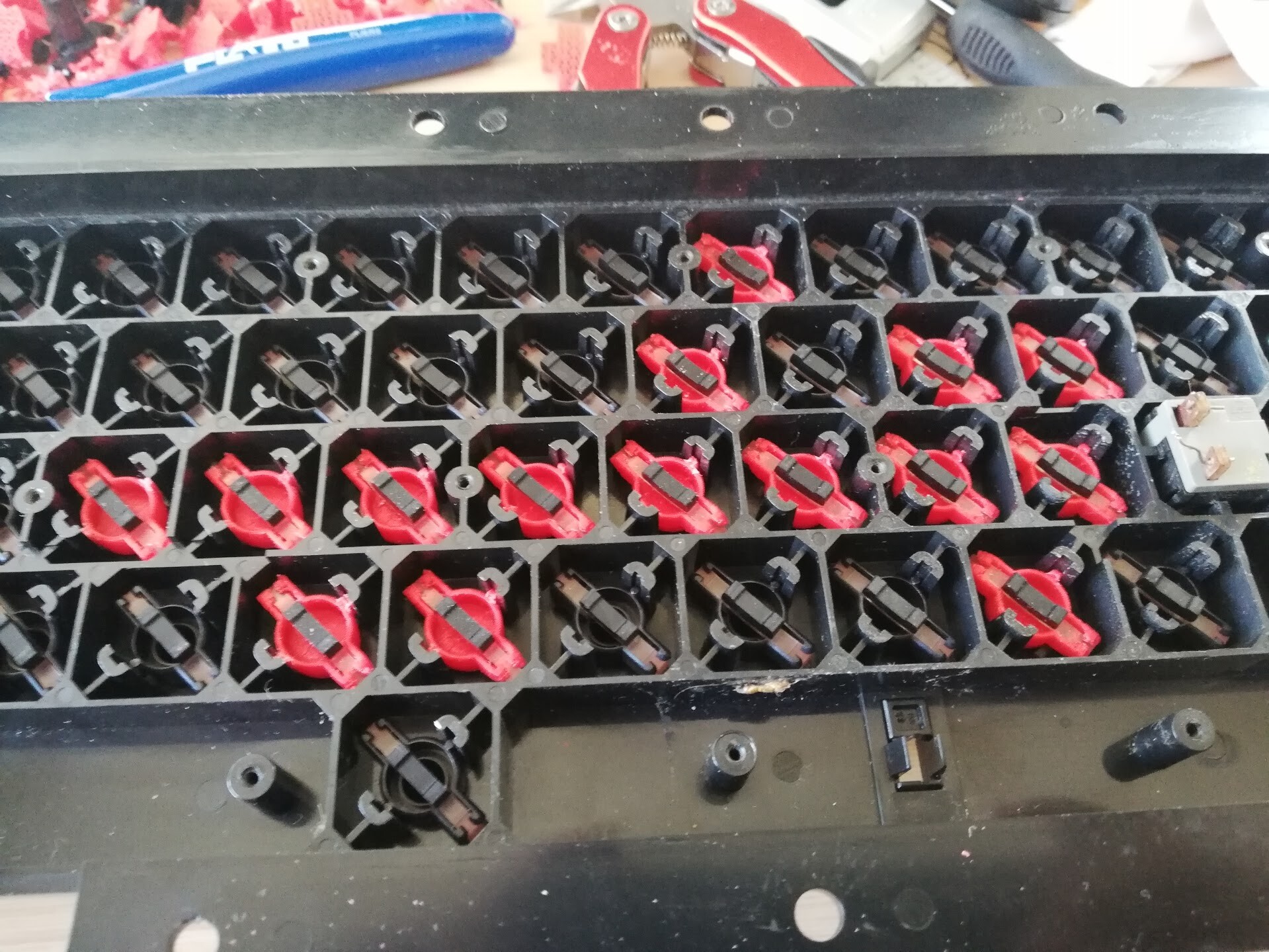
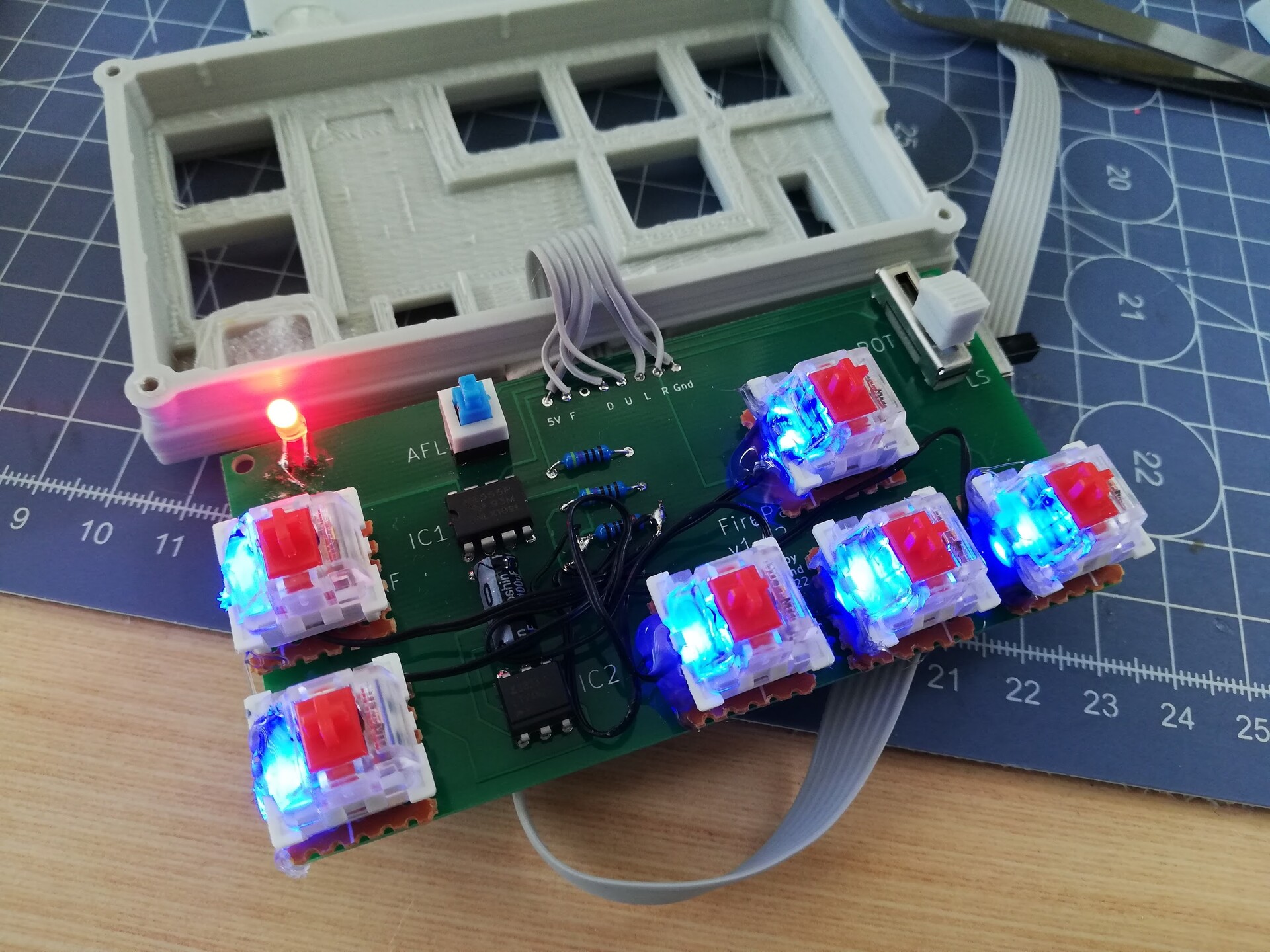
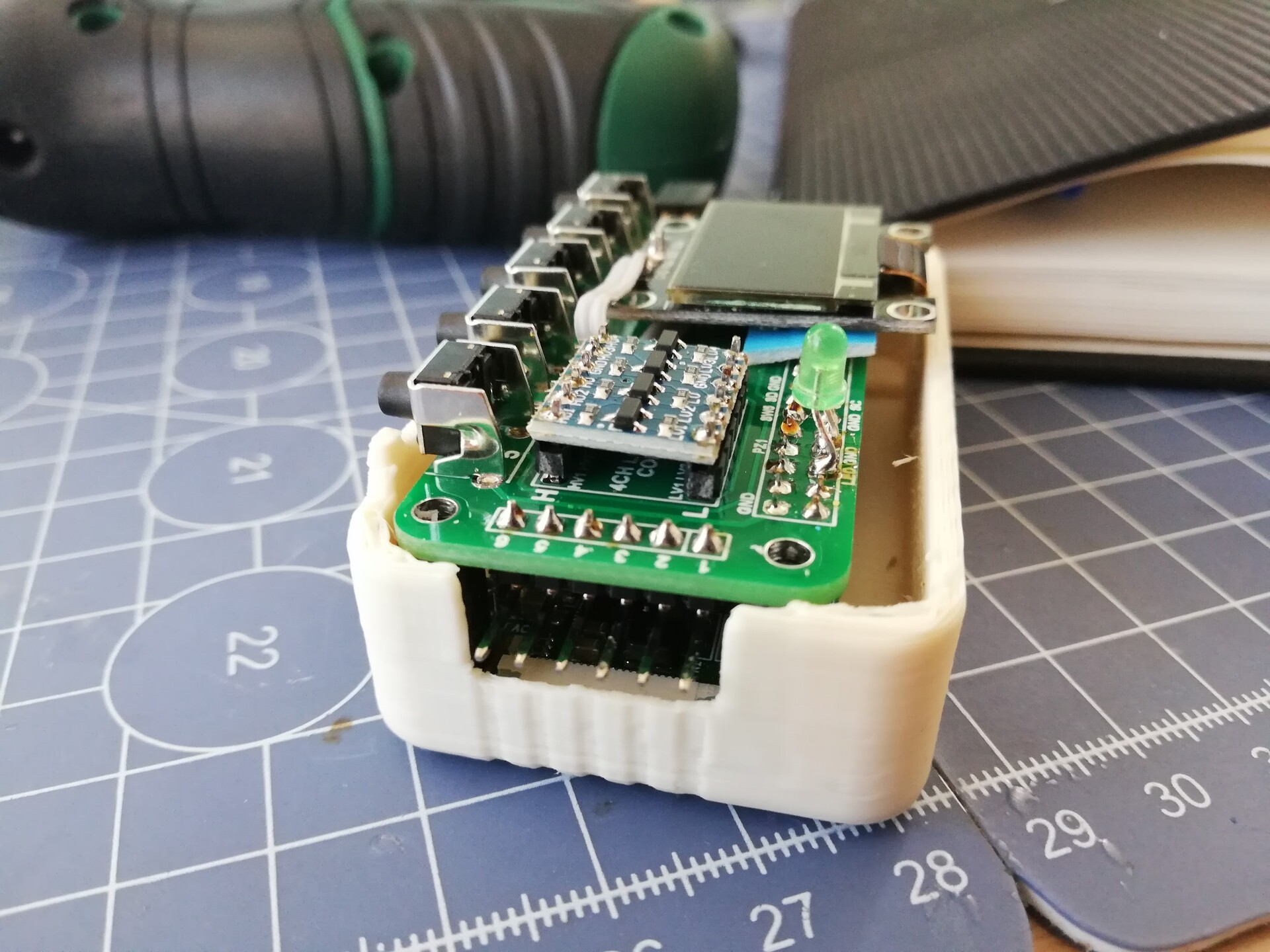
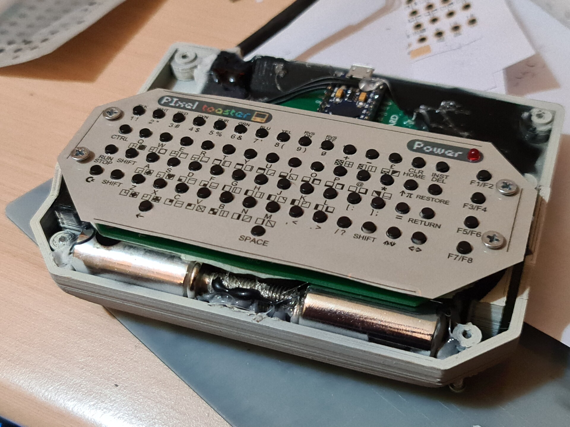
After the printing I go for the weights. Since my design has a shifted weight center because of the angular screen case, I needed add extra weight in front of the keybaord unit. So I found some steel screws to use for that.

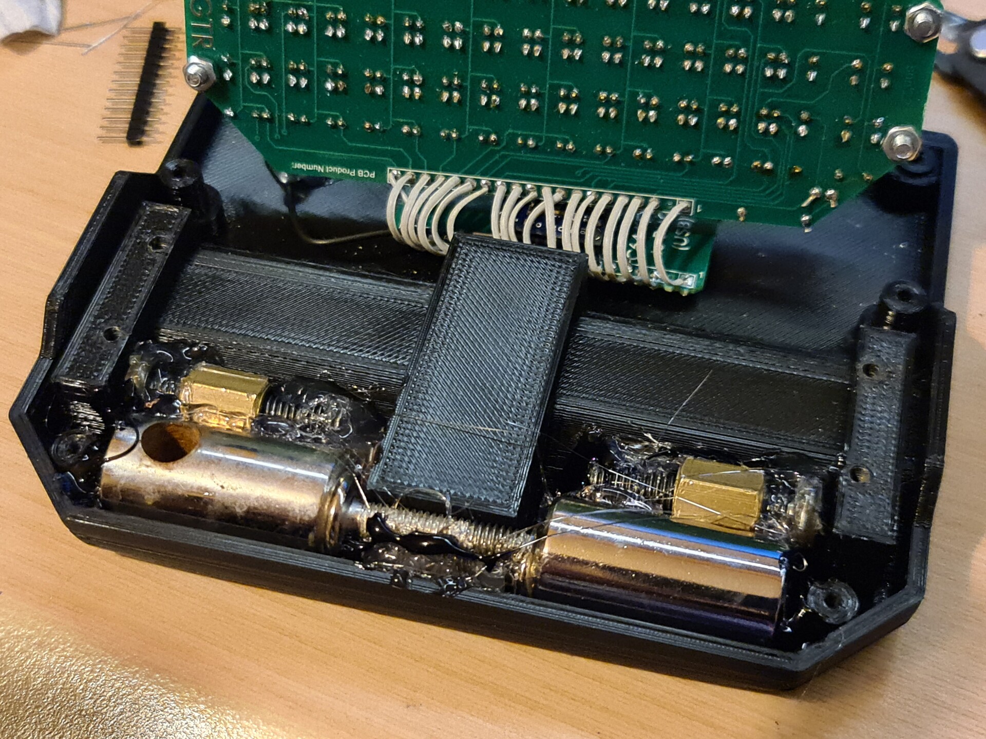
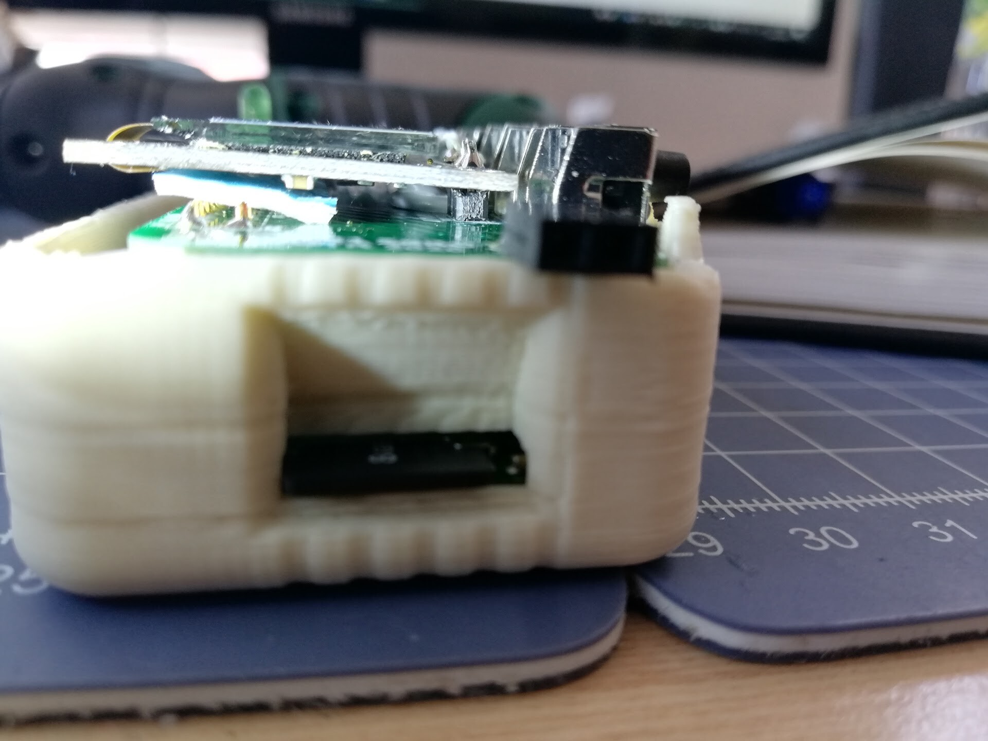
Since I'm using conductive materials as weight, to prevent any short circuit under the PCB, I isolated the back part with 3 layers of masking tape.

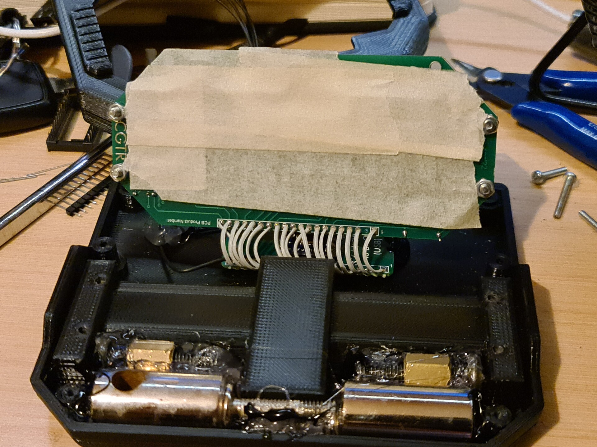
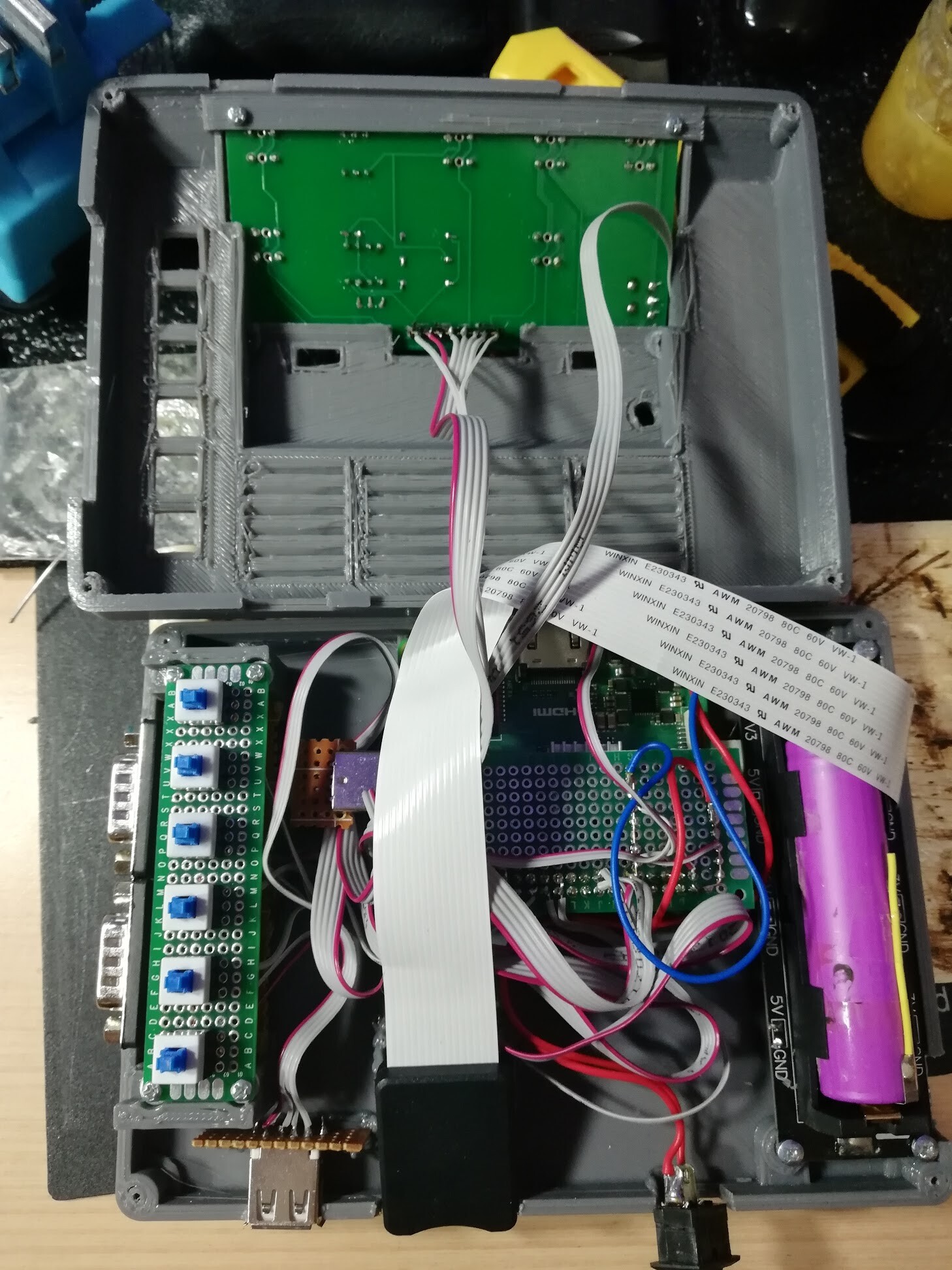
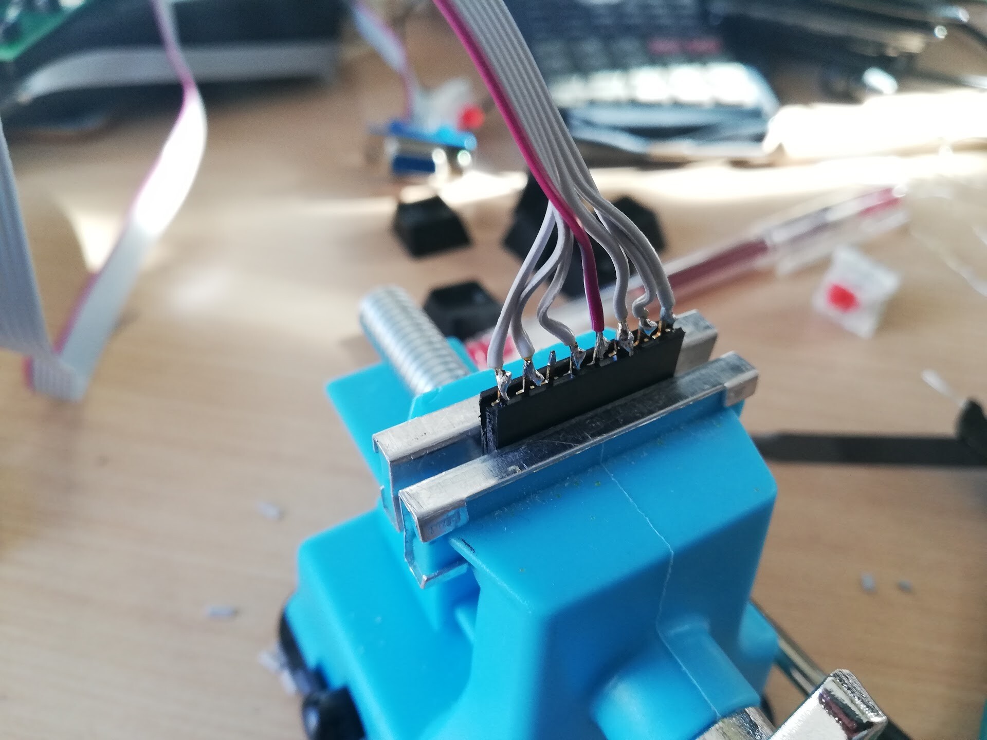
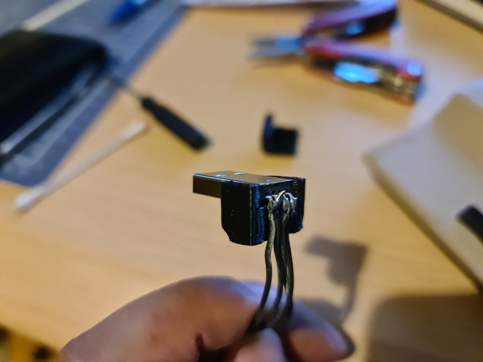
I also hacked the Promicro's usb input to use it as an extension cable. So I soldered 4 cables to relevent areas where you can see on this article.
https://www.instructables.com/Fixing-an-Arduino-Pro-Micro-the-USB-Port-Came-Off-/

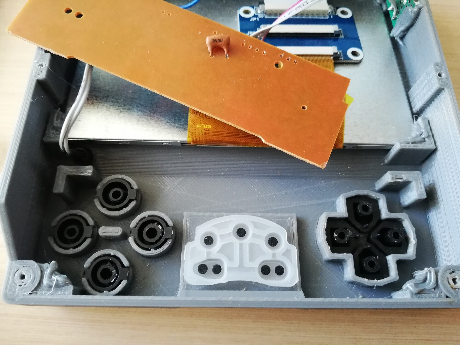
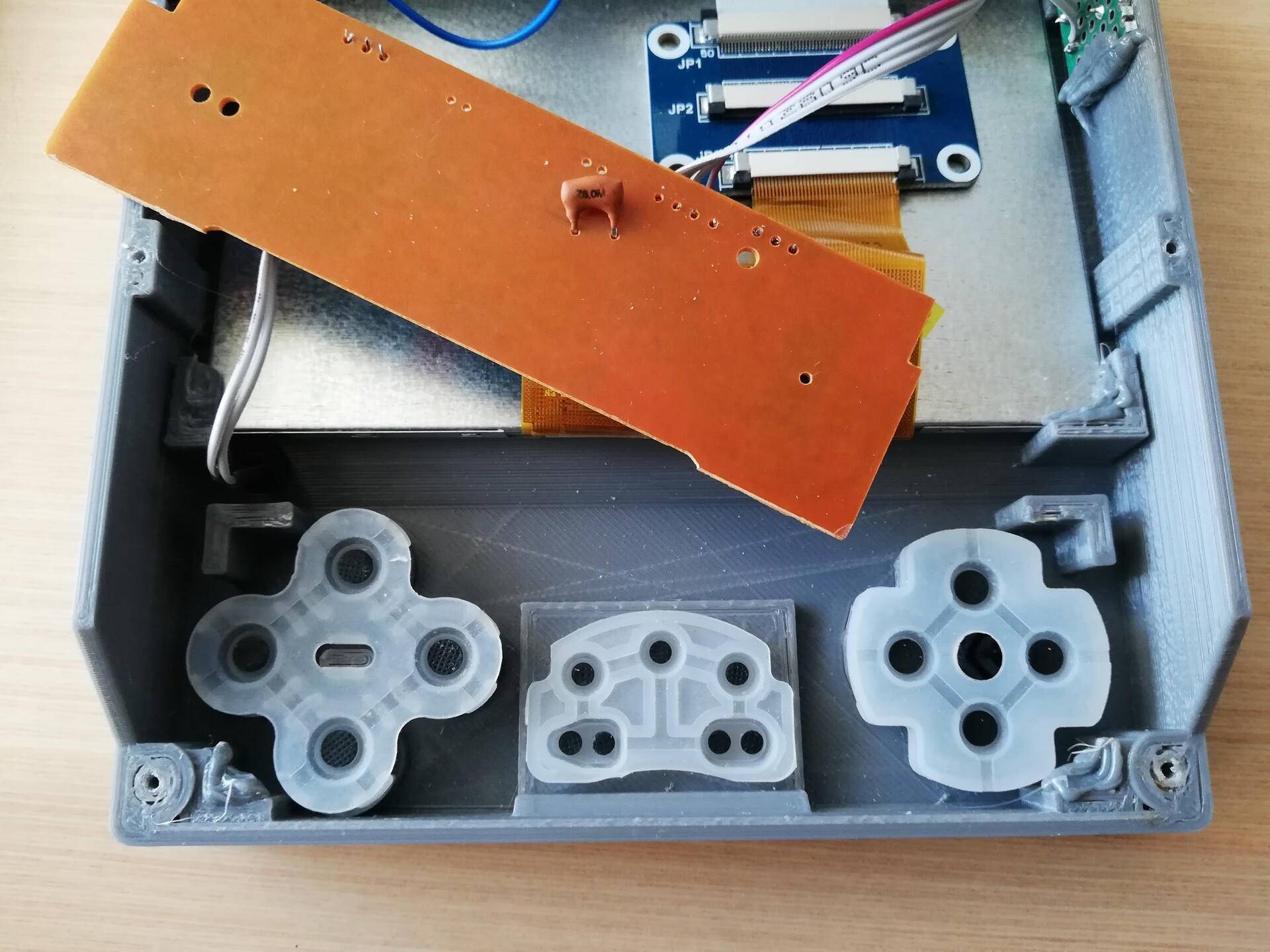
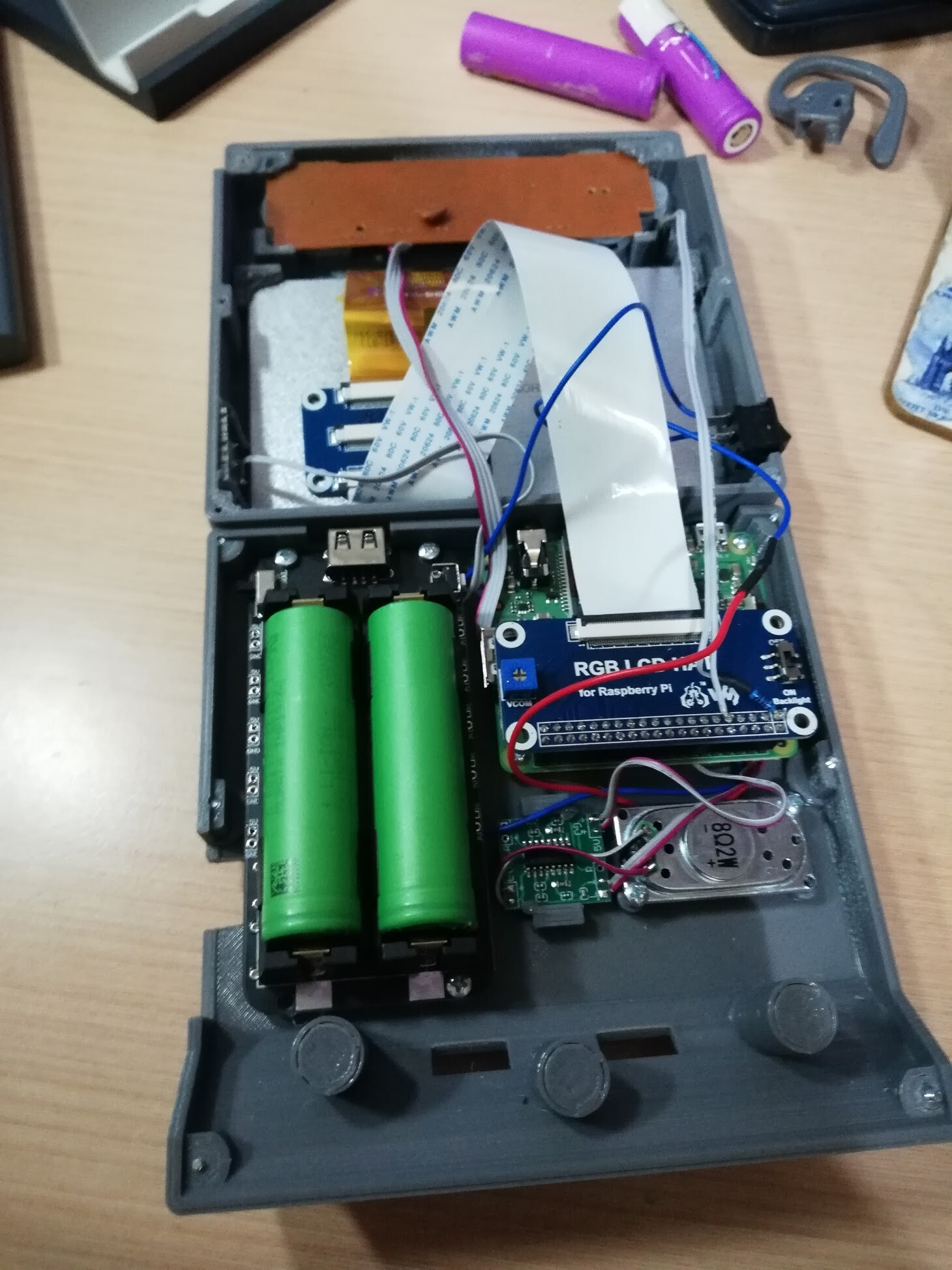
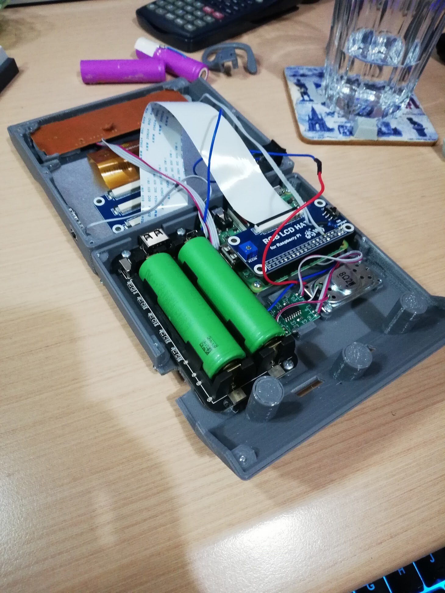
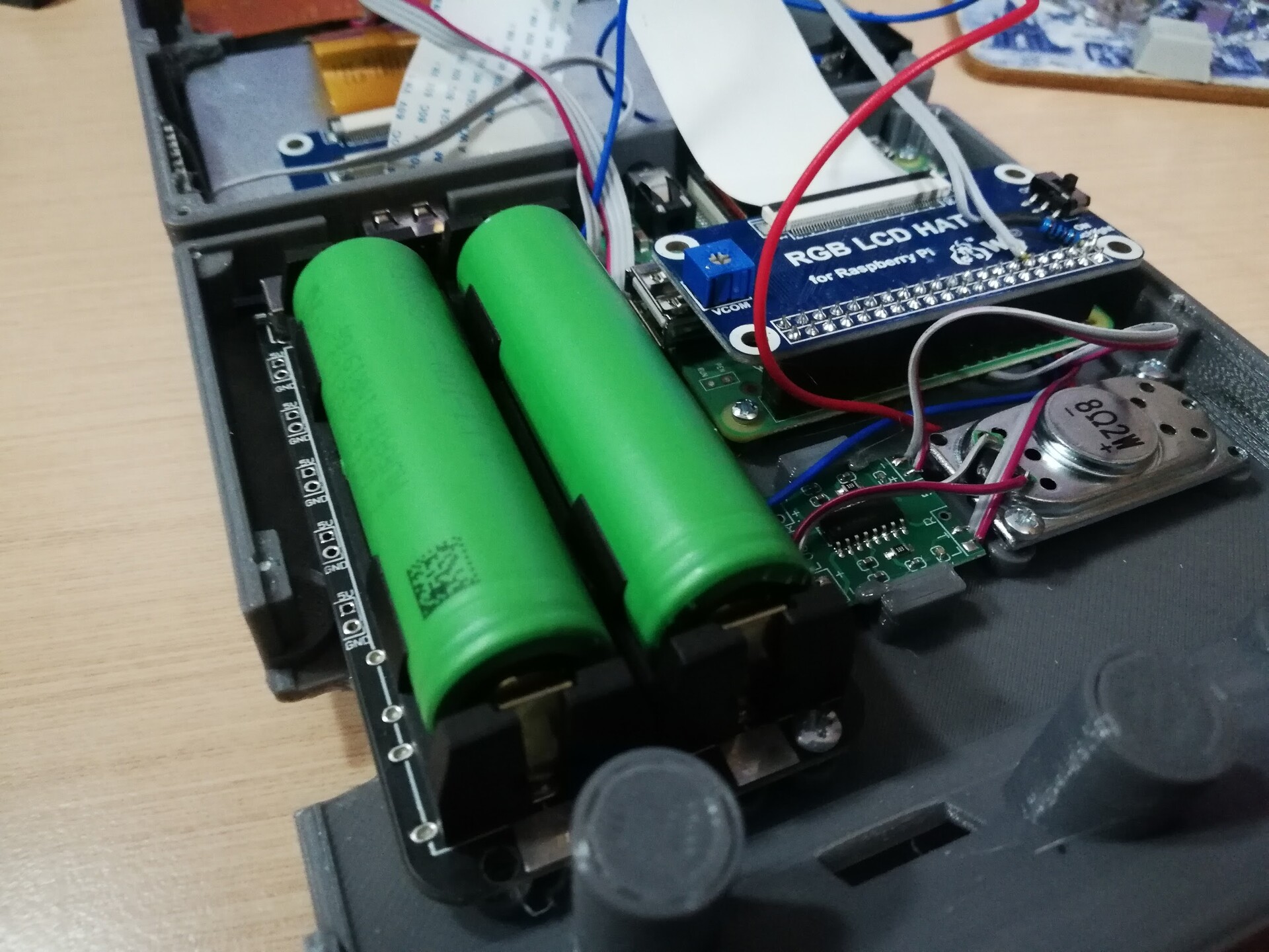
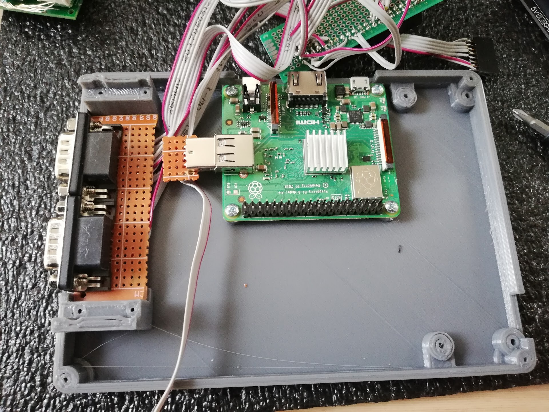
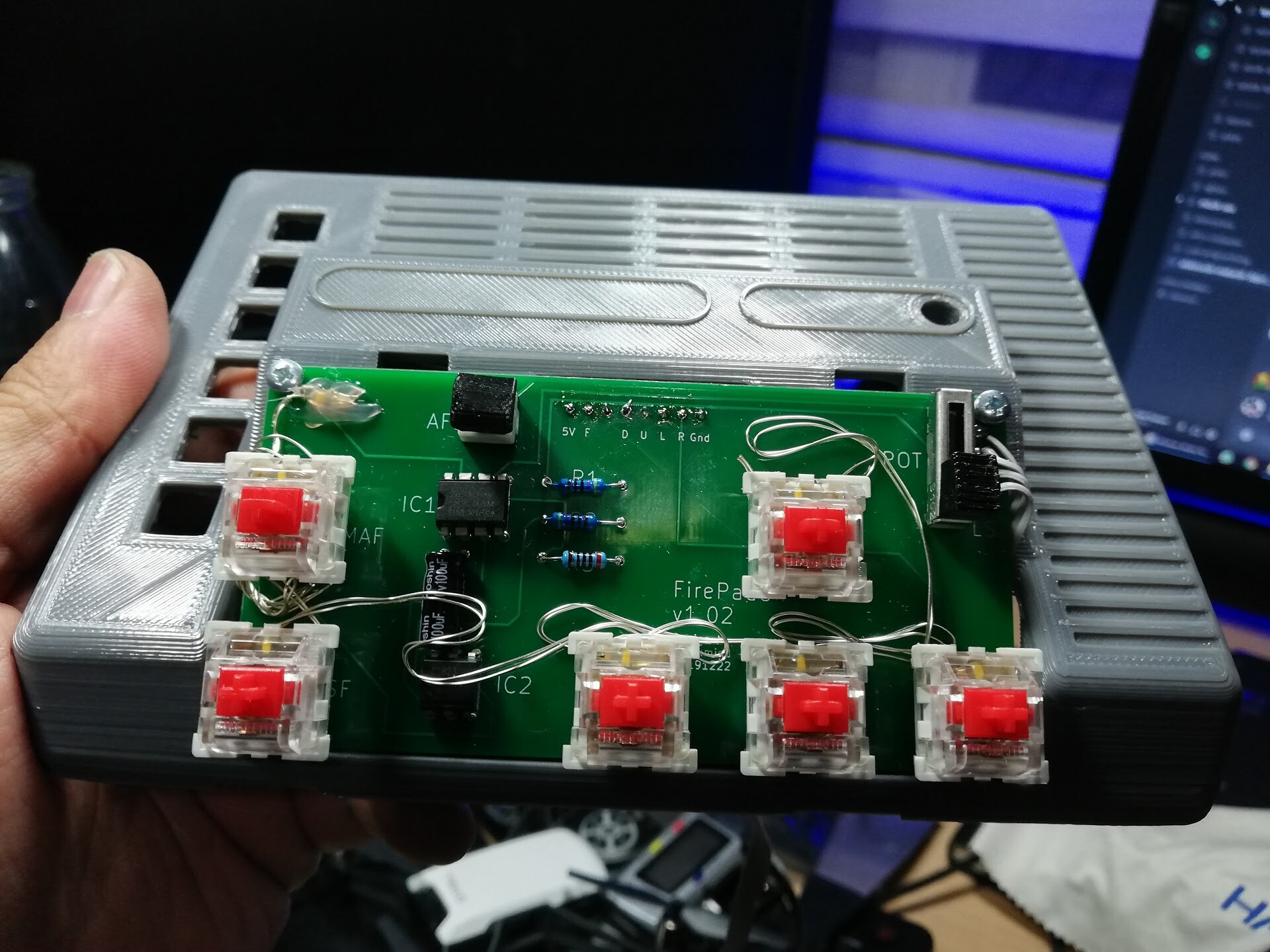
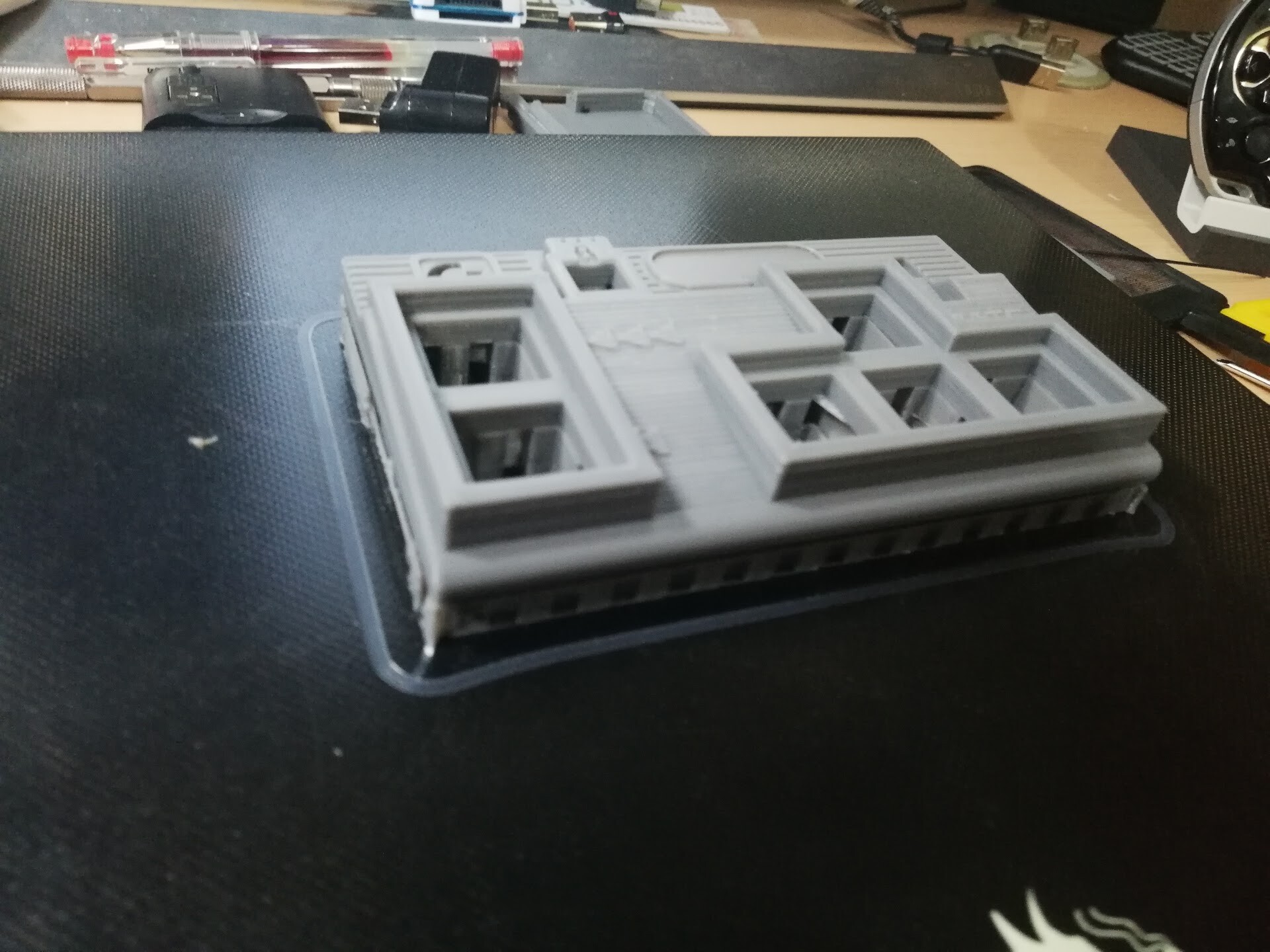
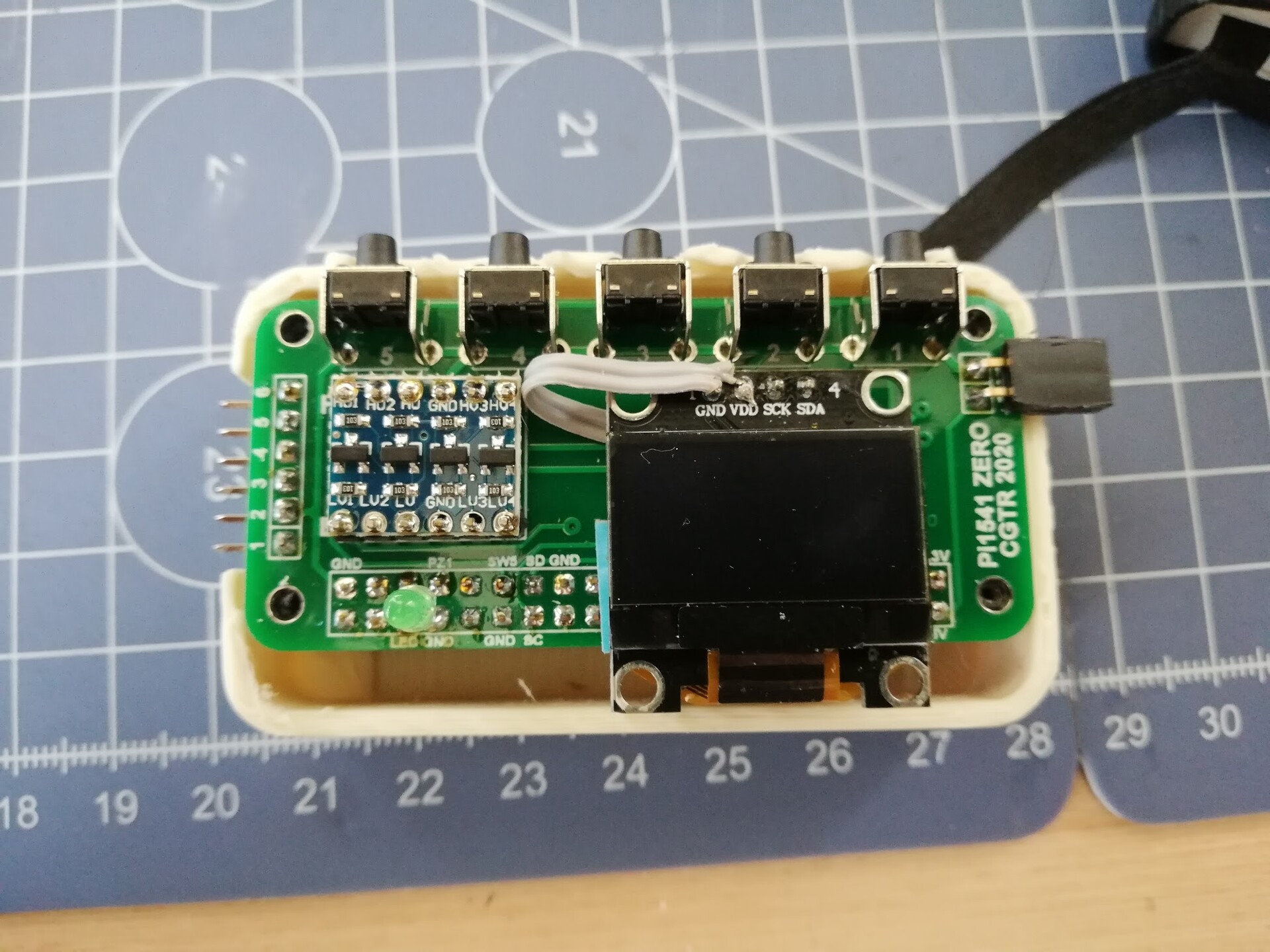
This is the actual look of the bottom part of the case.

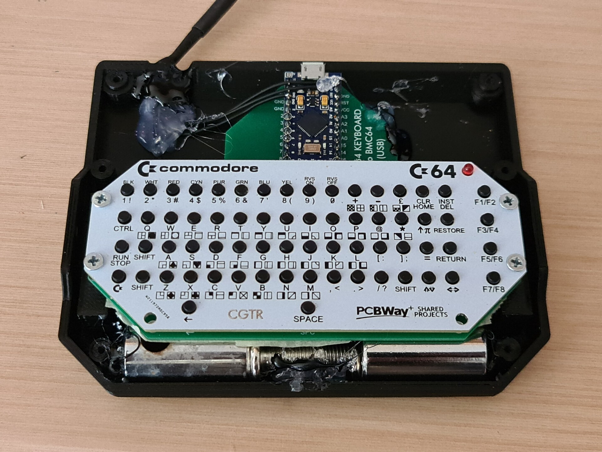
And the weights and keyboard works!


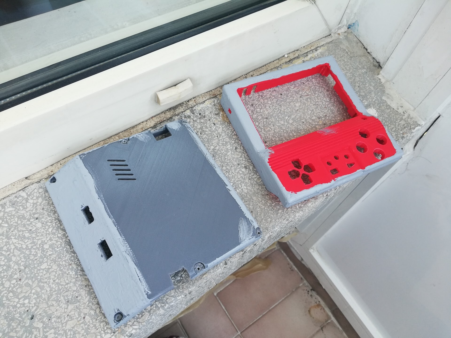
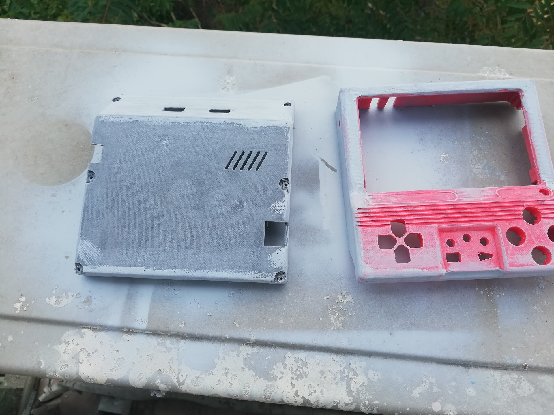
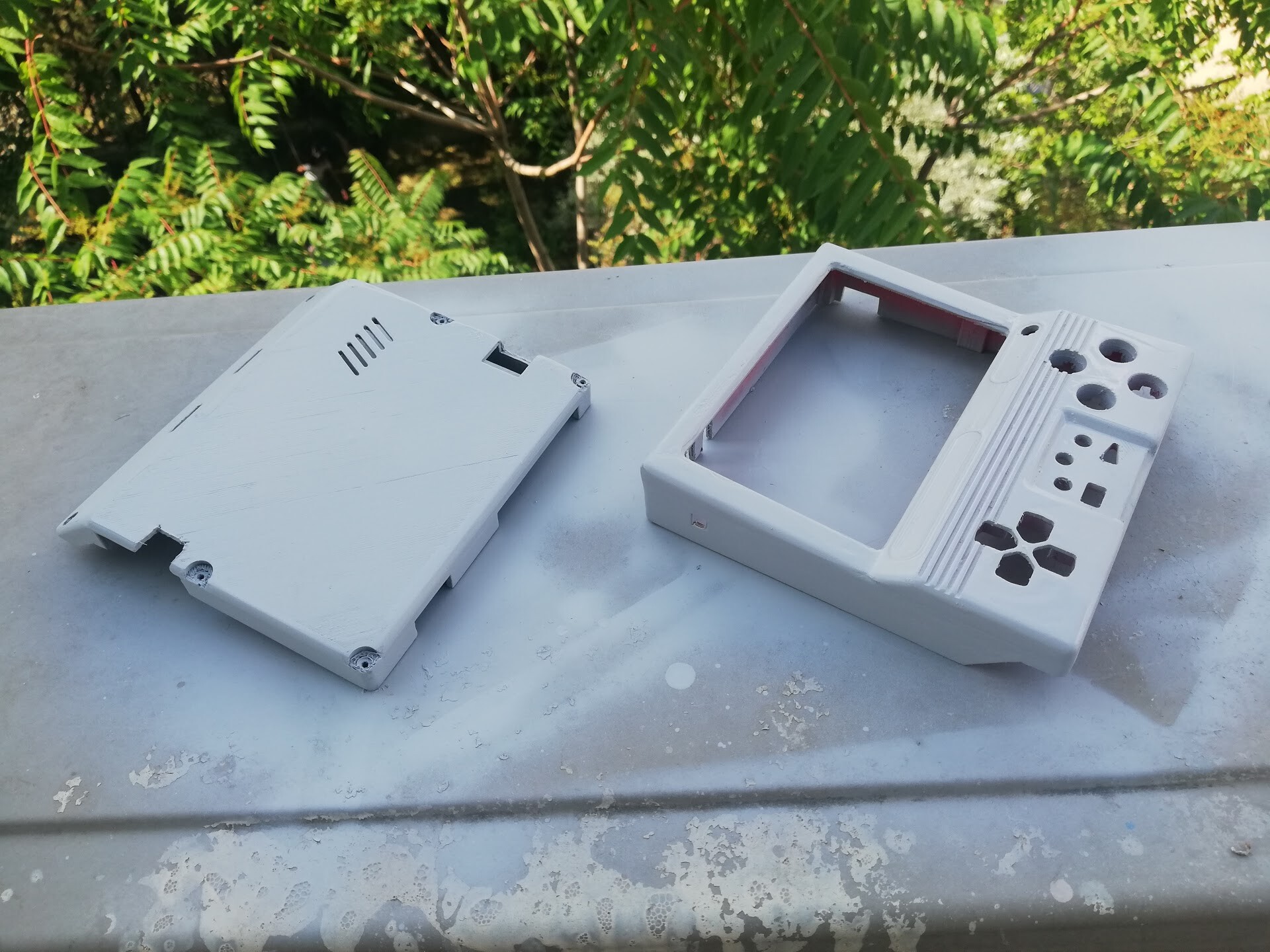
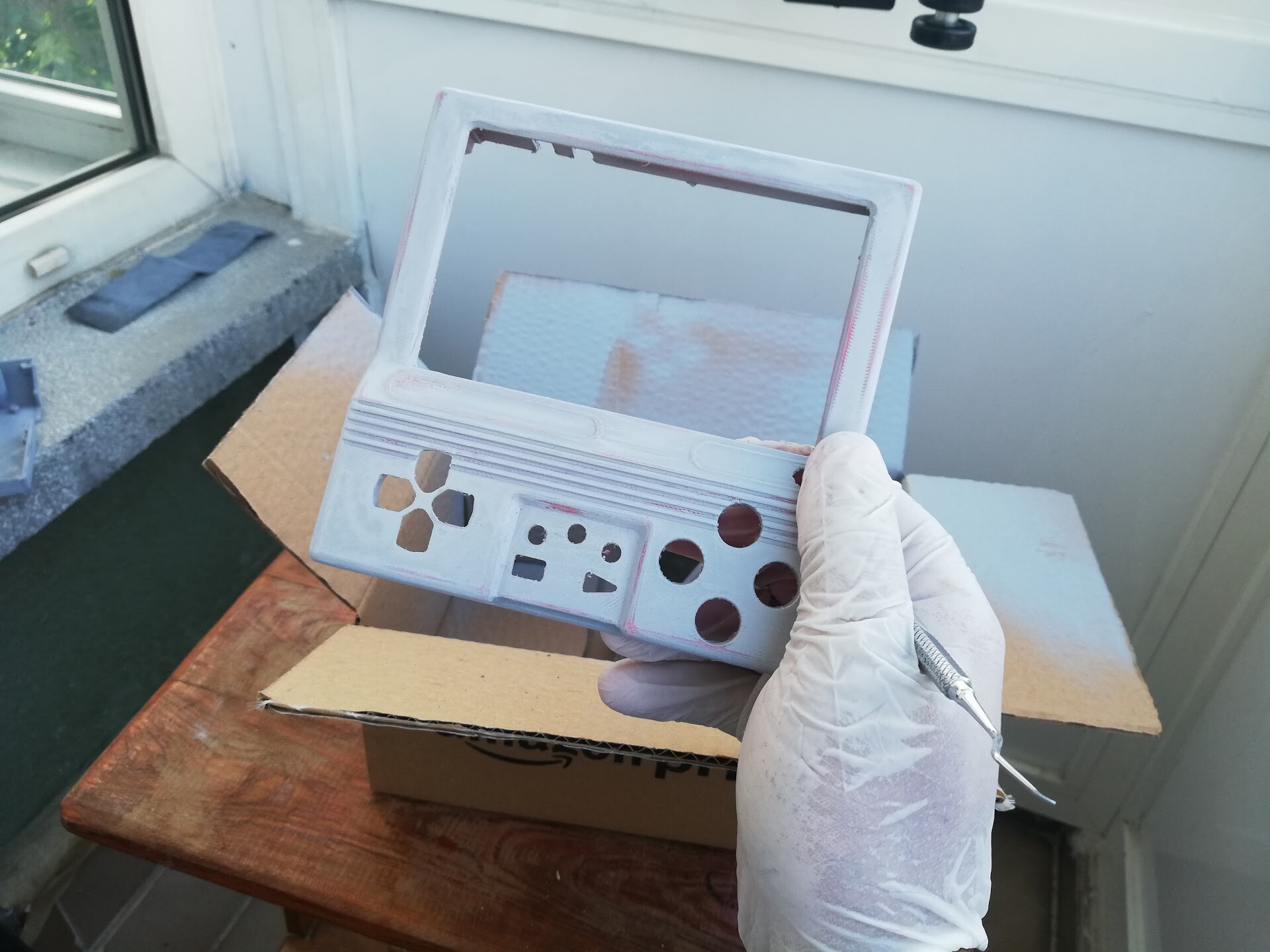
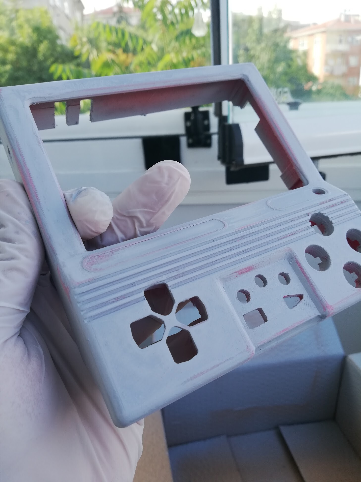
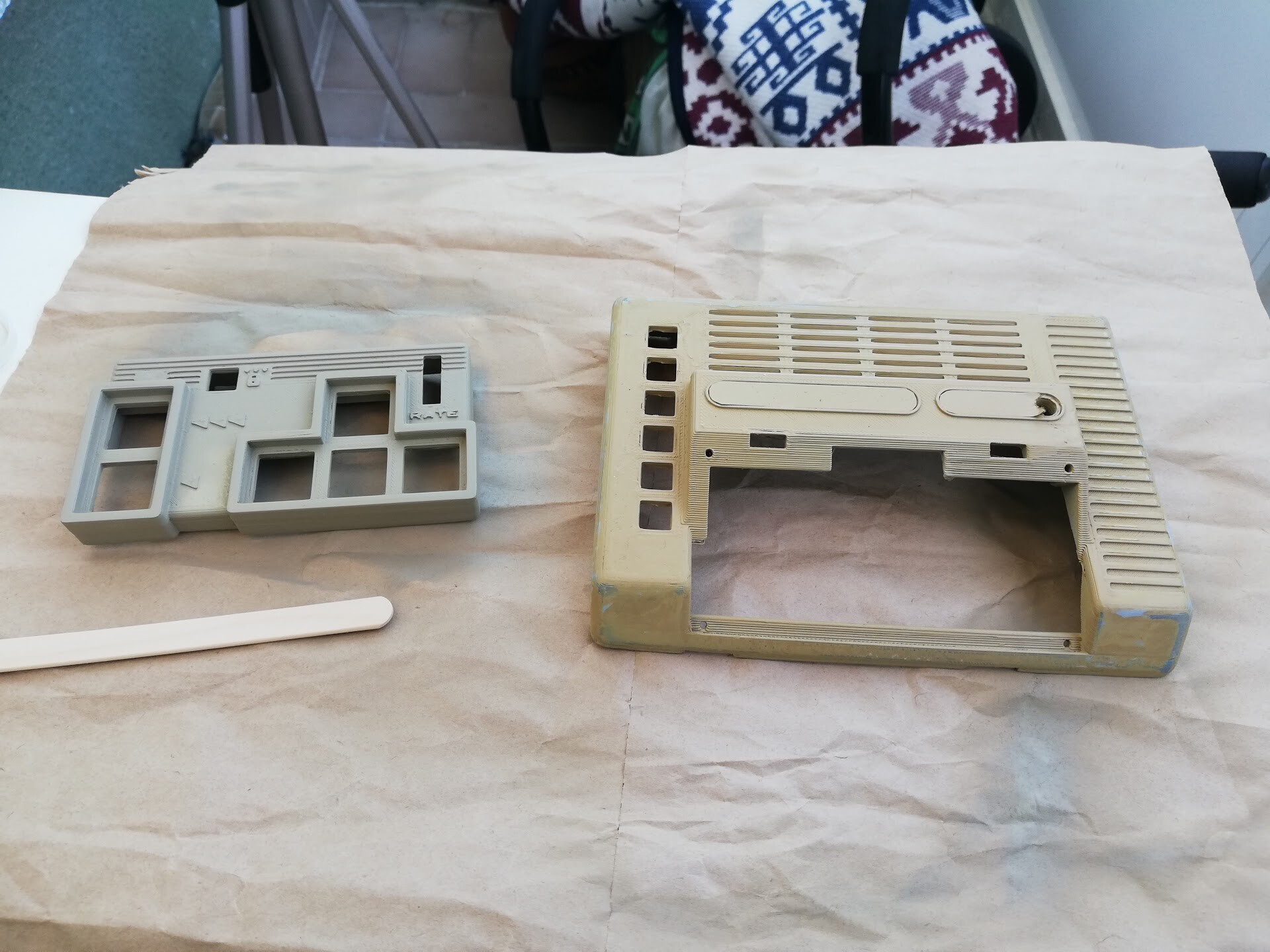
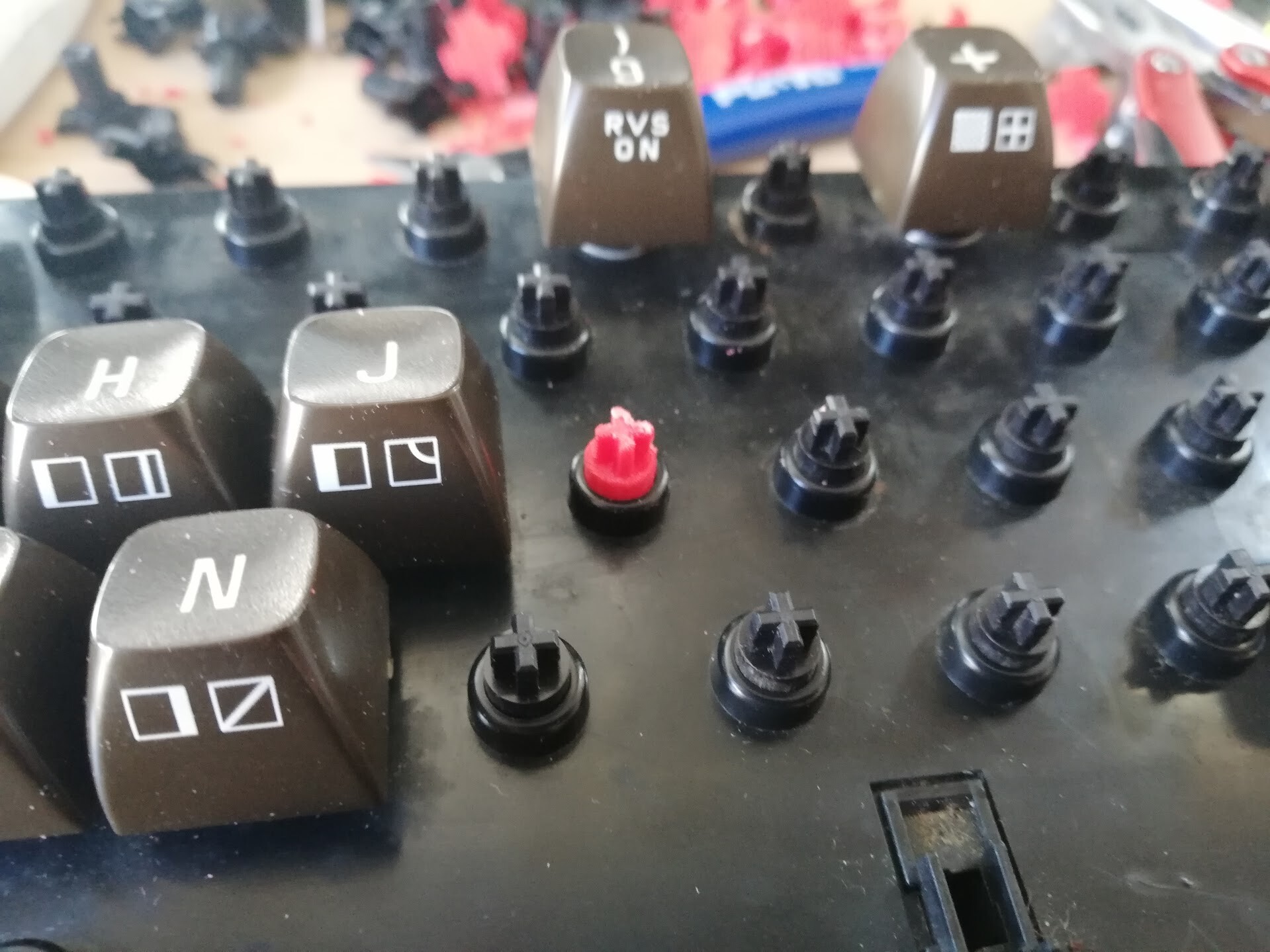
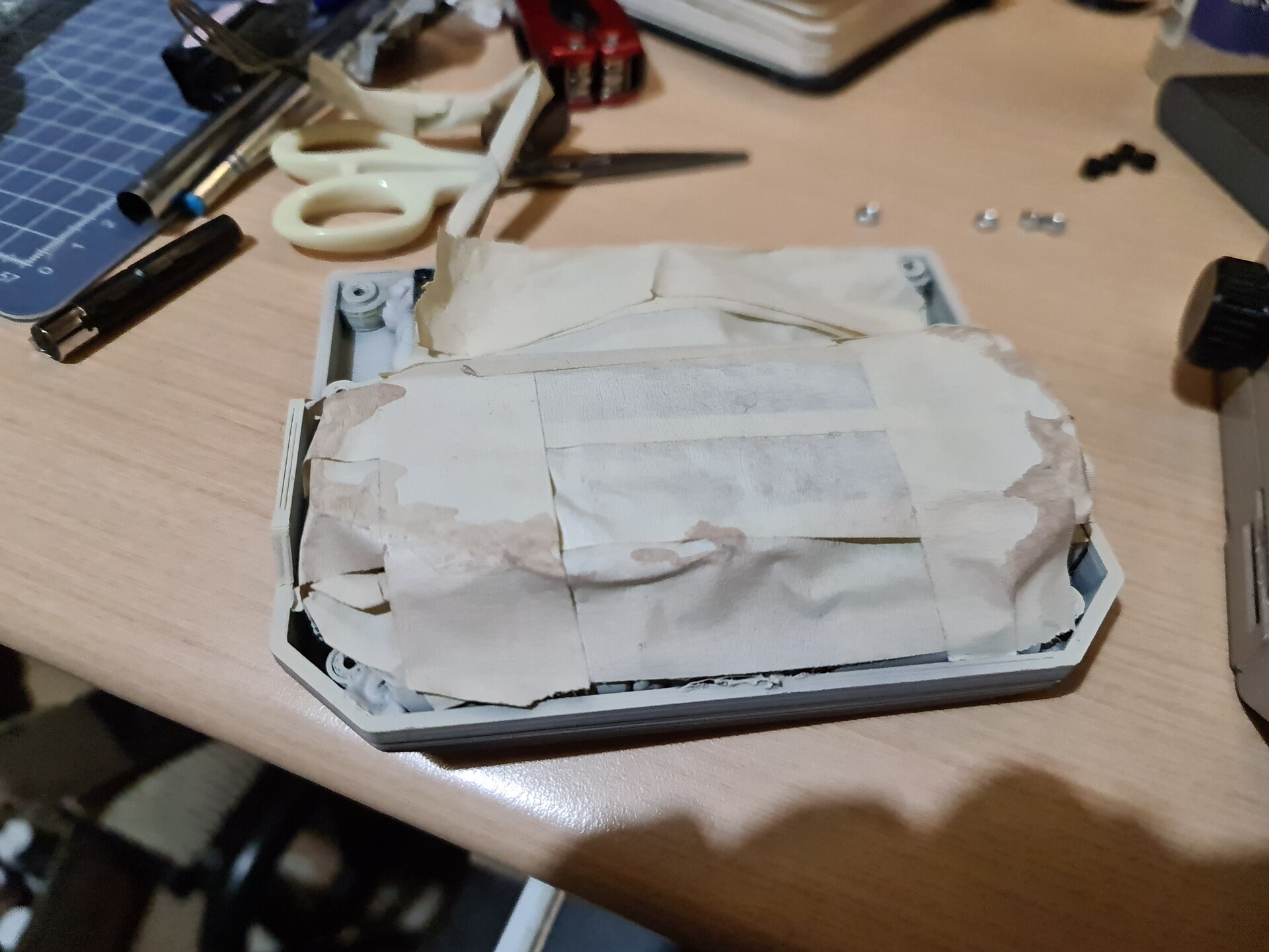
Before painting the parts, I masked the electronic components and the attachment hooks.

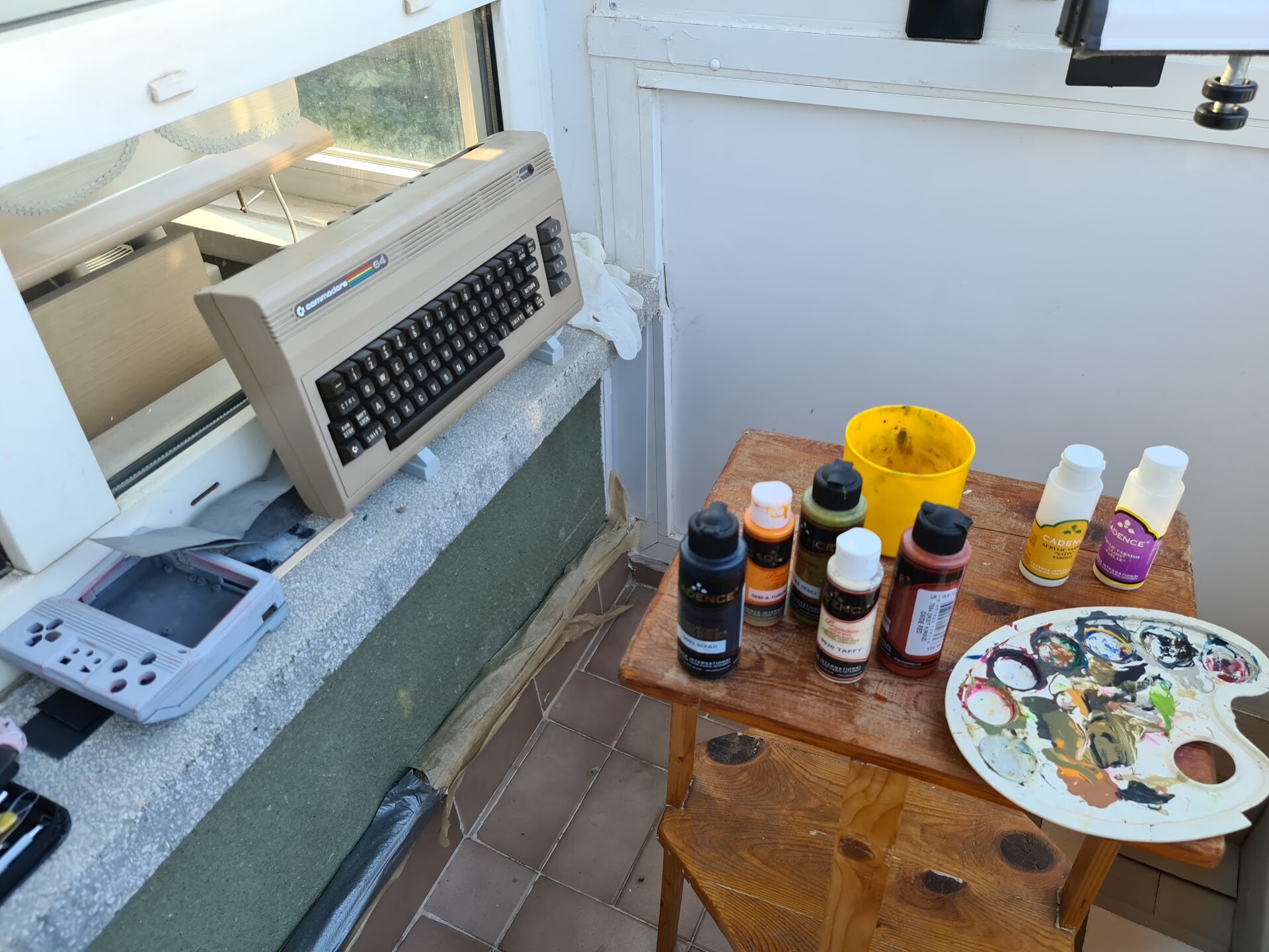
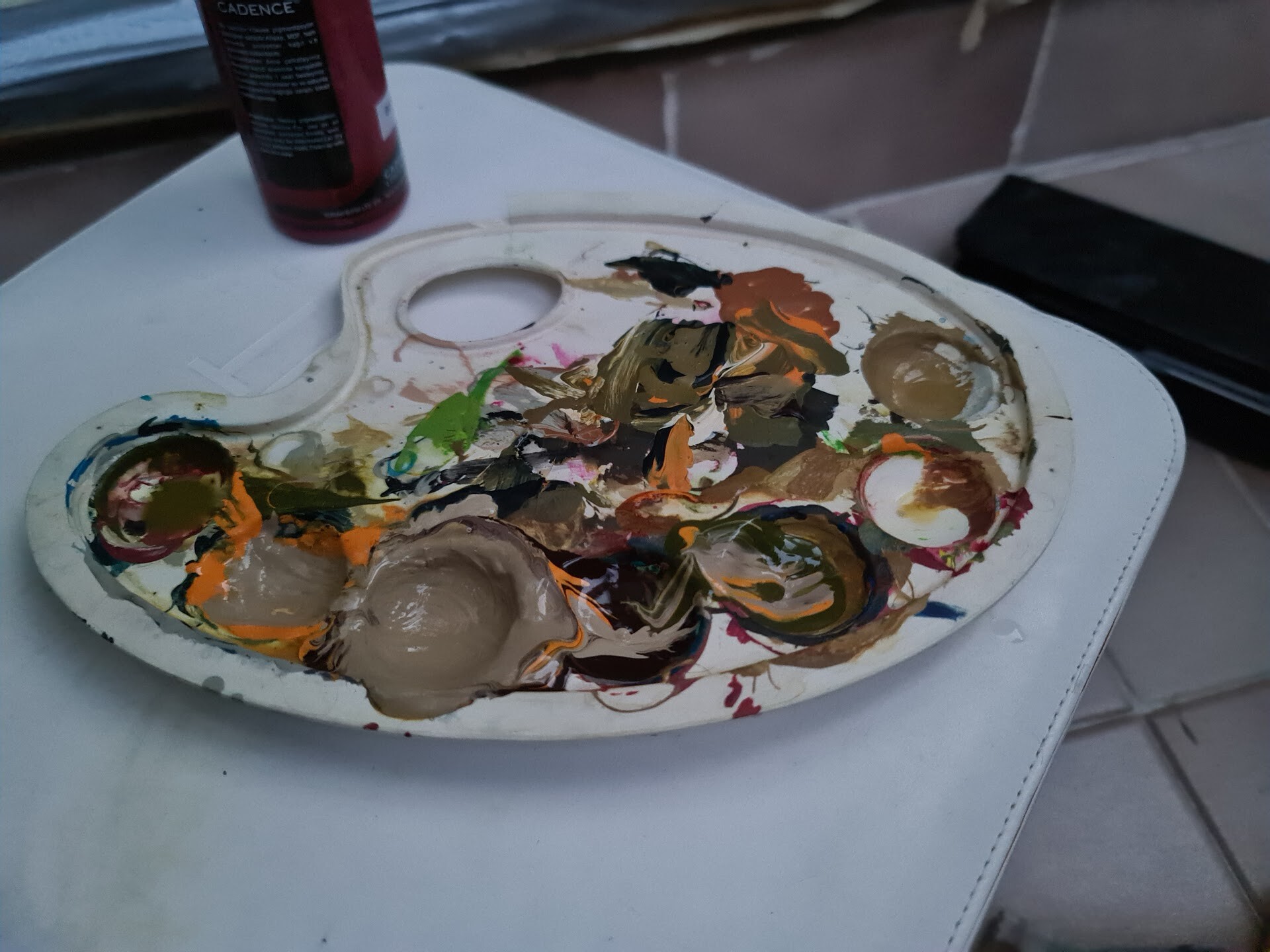
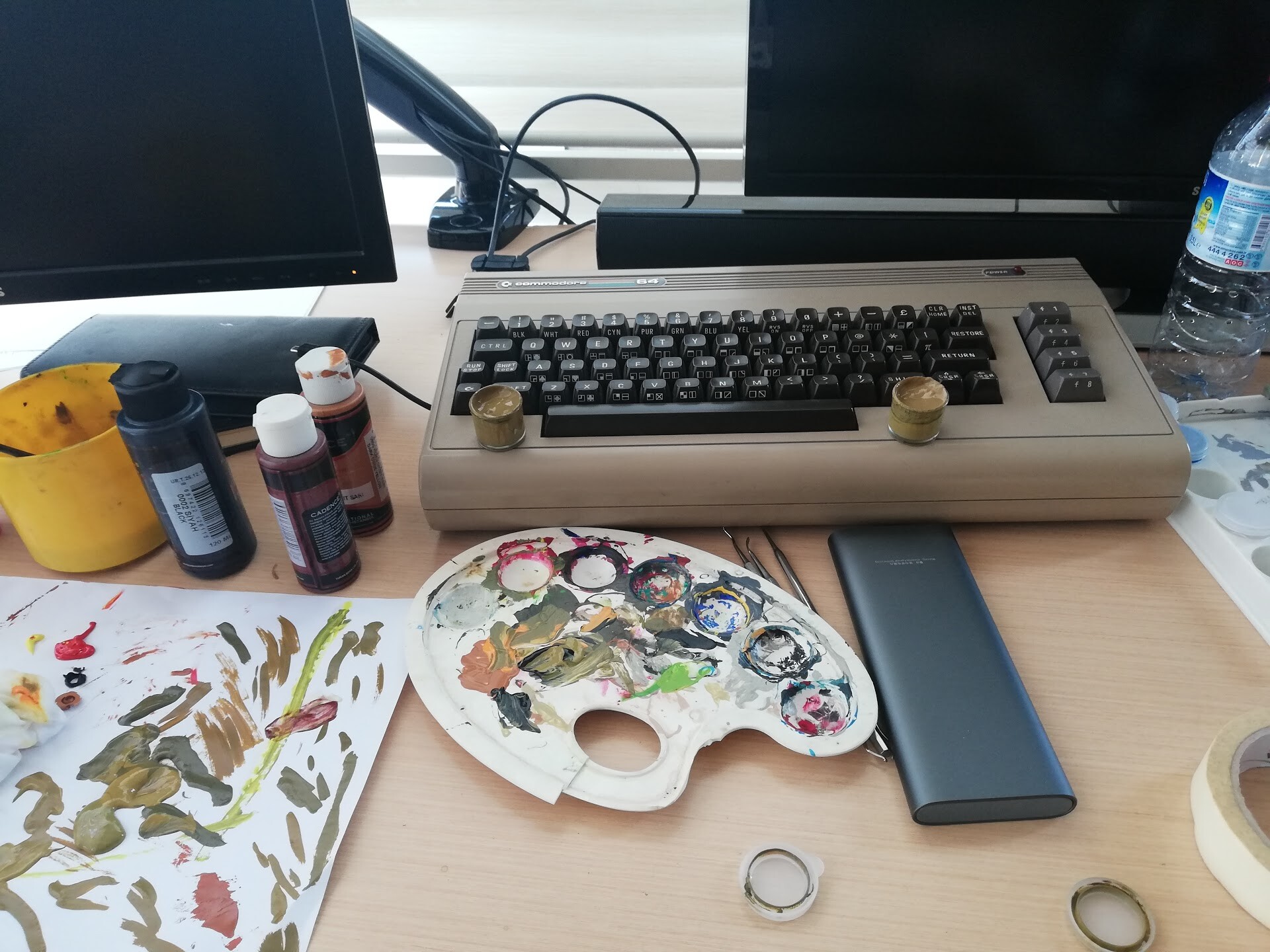
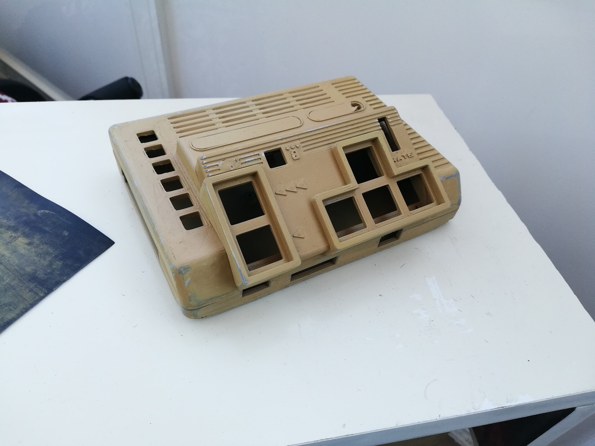
I used acyrillic paint with a special mixture to get the famous "Commodore Beige". Here is the recipe: %60 Mocca %40 Desert Brown :)

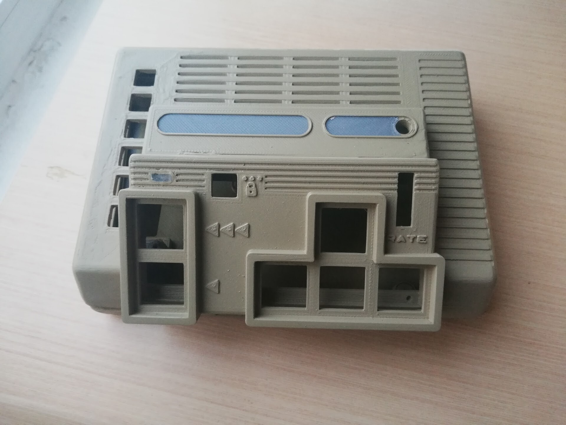
%100 color match with the old painting.

Let's do an assembly.

At that point, the thing that bothered my was the white color of the faceplate. they can be ordered in few colors but any of them cannot match with the beige color. So I decided to change the color of it. Overpainting it with a thinner was not an option. because the surface was too glossy to hold the paint. 

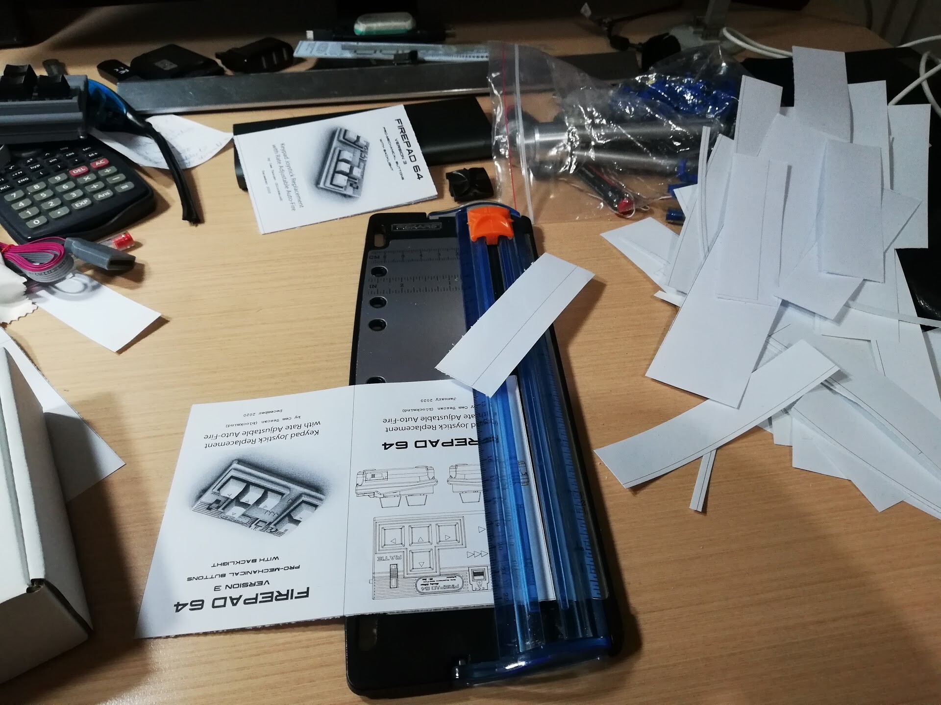
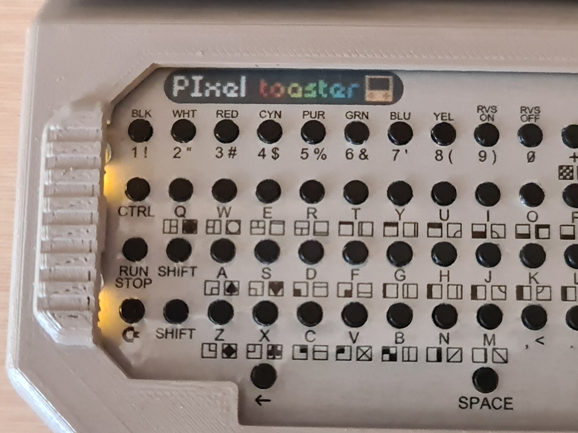
I found a strange workaround about this. I decided to print the same design with beige background with my color printer. But I printed the design on a sticker paper.

Next I needed to use my laminator device to cover the paper with PVC. Because standad paper would worn out in time while using the keyboard.

Laminators work with heat treatment to make the PVC sheet welded with the paper. Perfect way of protection. To make it one sided to my printed sticker, I added an extra layer of standard paper to the backside of the sticker.

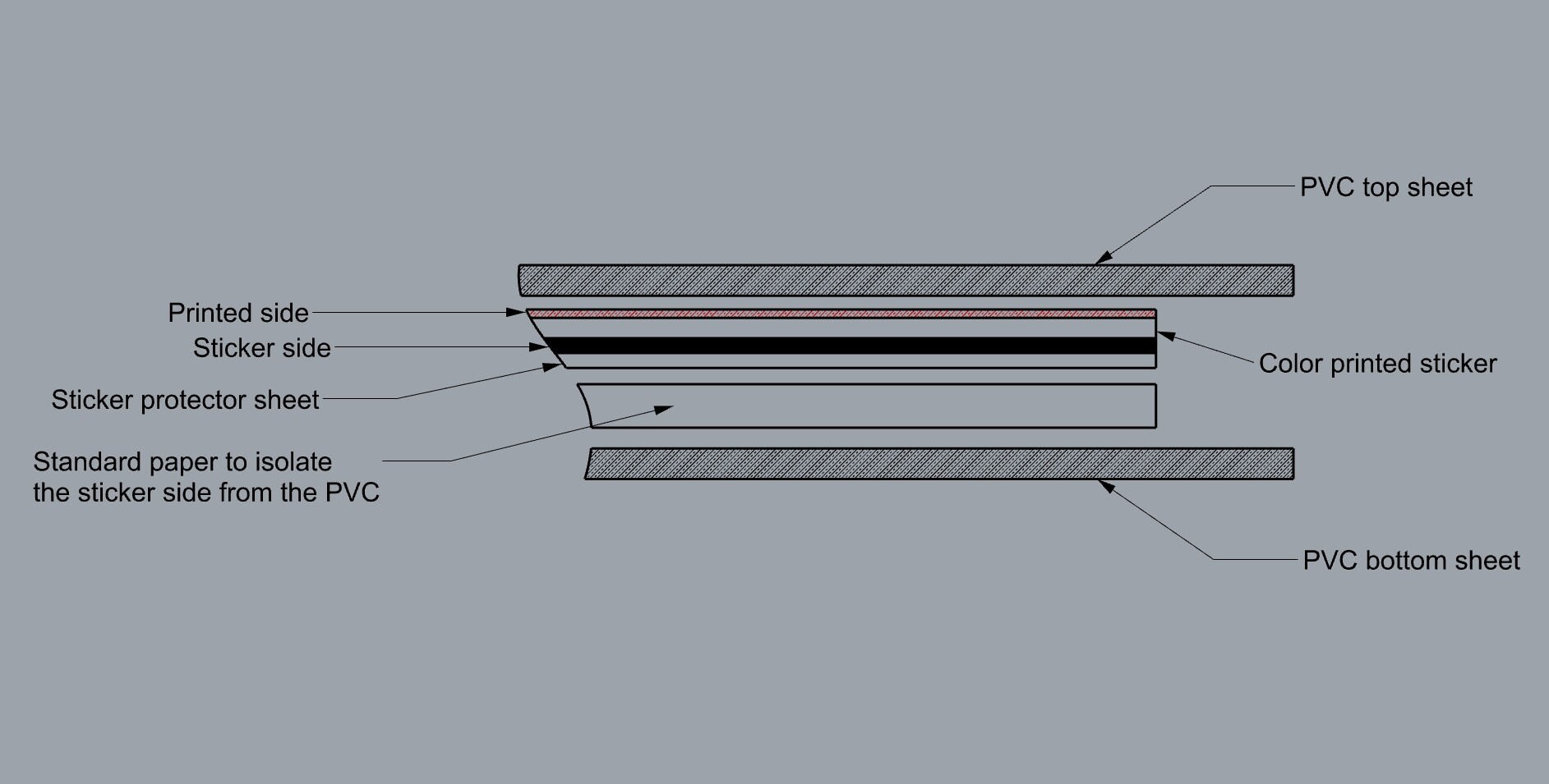
This way I had my sticker PVC laminated on the printed side where I can also easily peel off the cover for the sticky side.

My next problem with this printed keyboard layout was the holes. These holes are drilled by machines, so making holes by hand was not an easy task. I also printed the outline of the holes and to make the holed I modified a pen as a punch pen :)

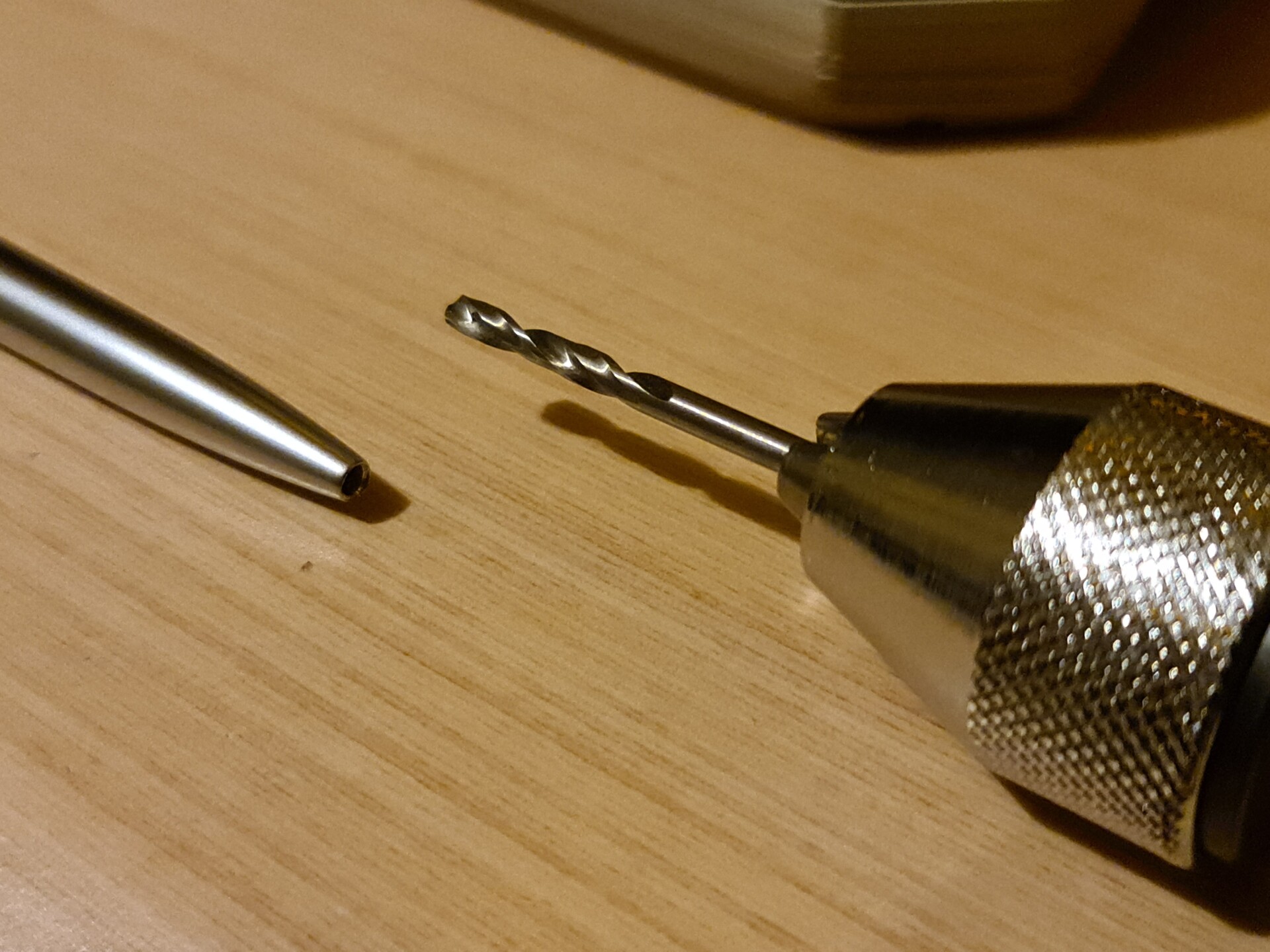
I used various drill bits to enlarge and sharpen the tip of the pen.

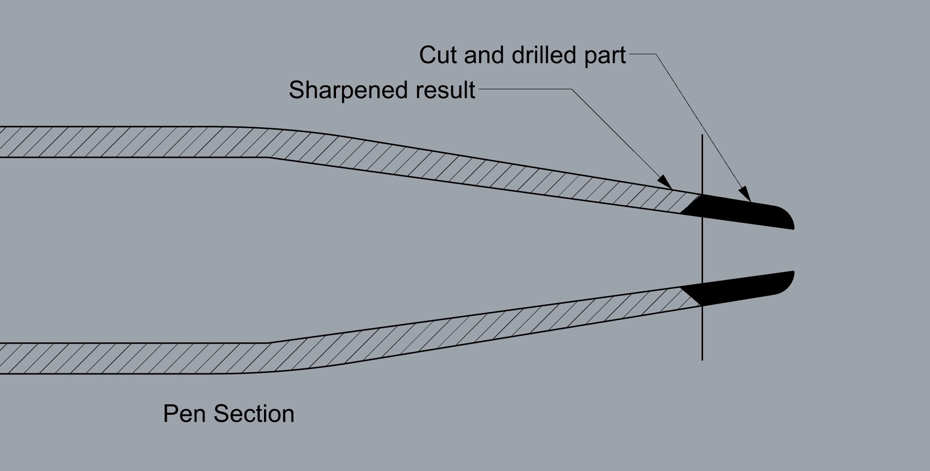
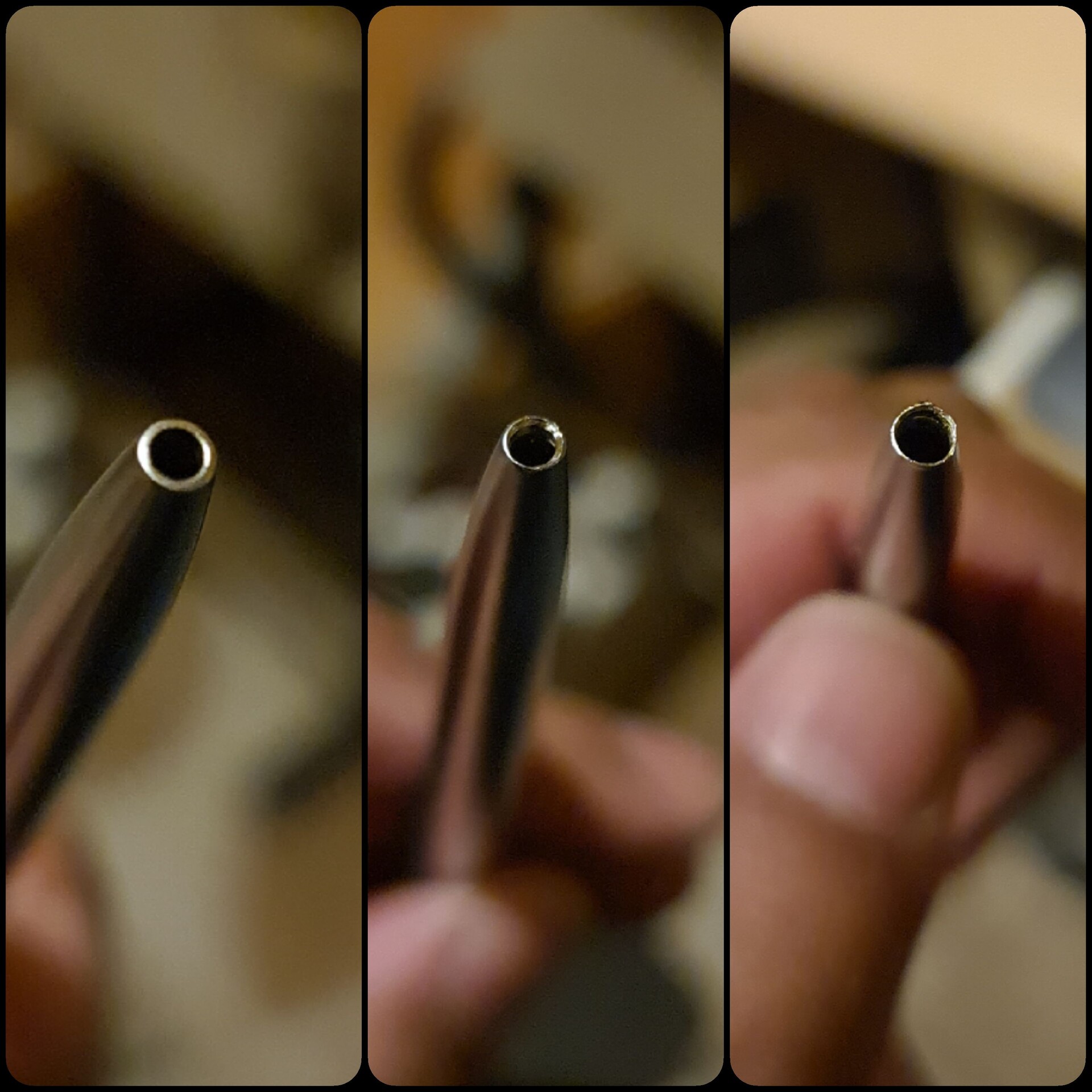
So I used this punch pen to punch the holes.

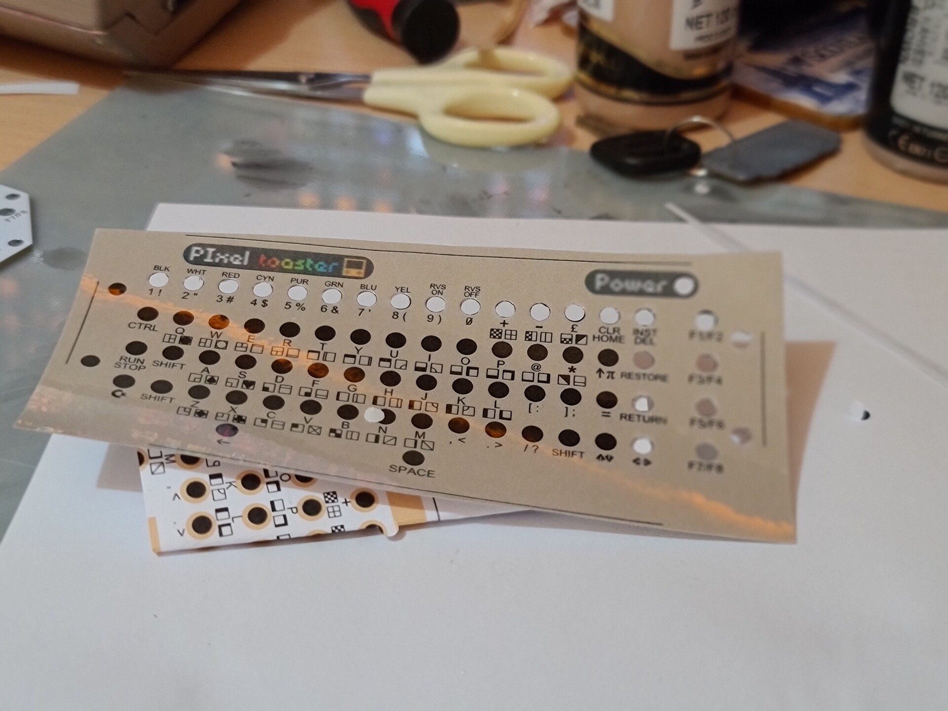
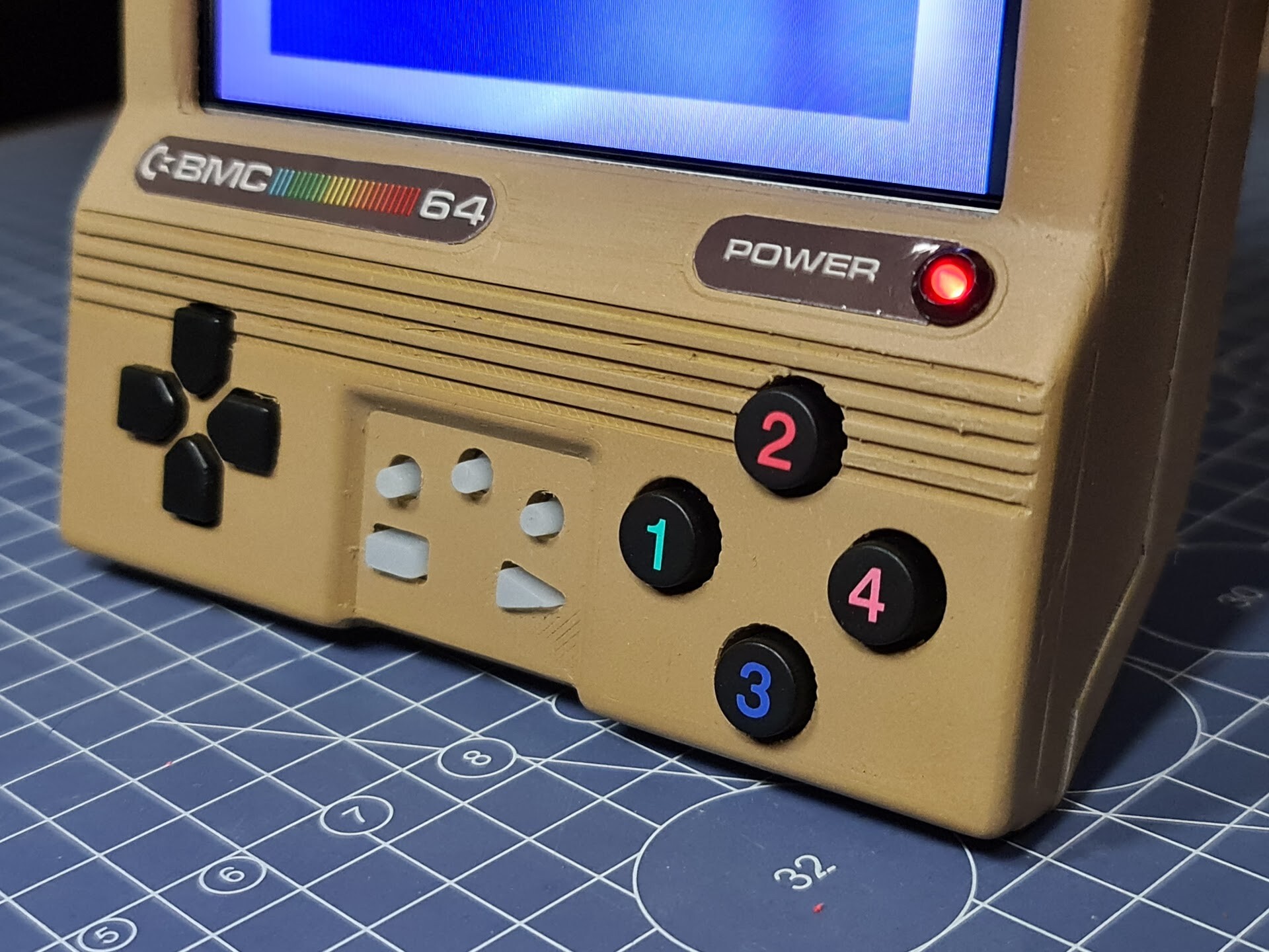
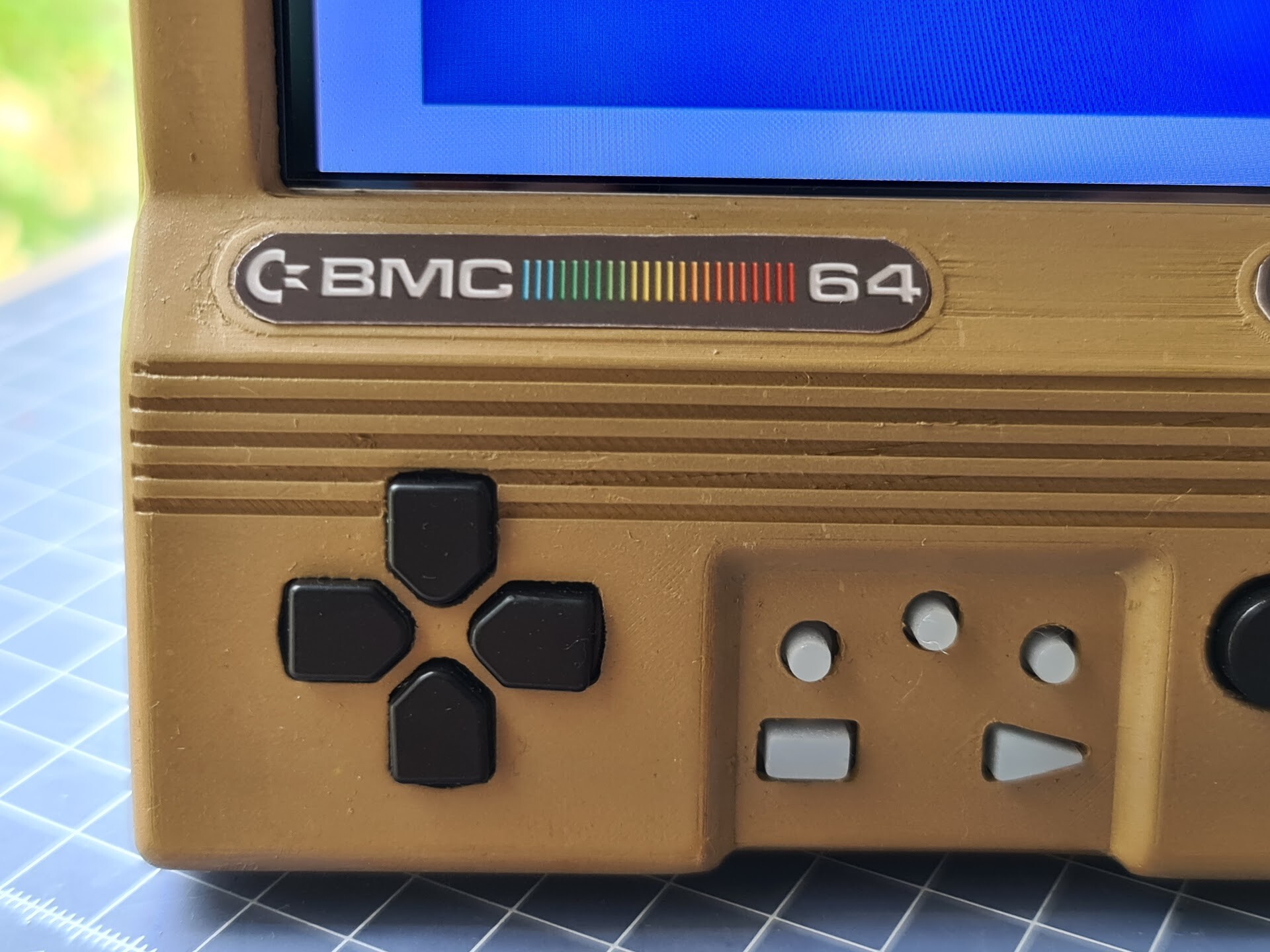
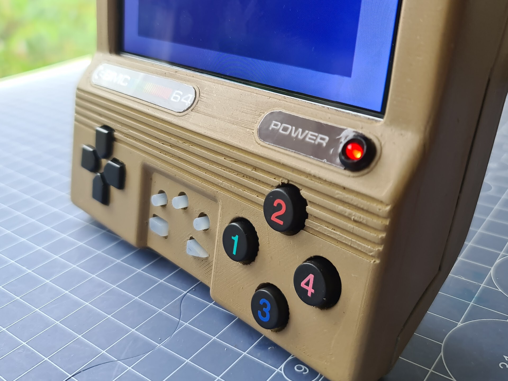
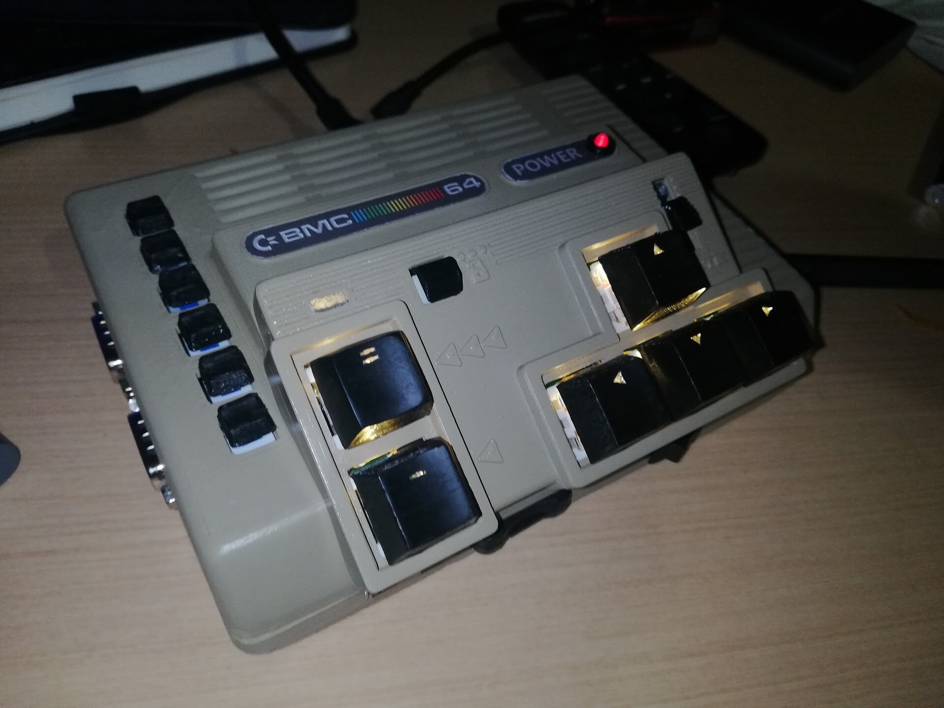
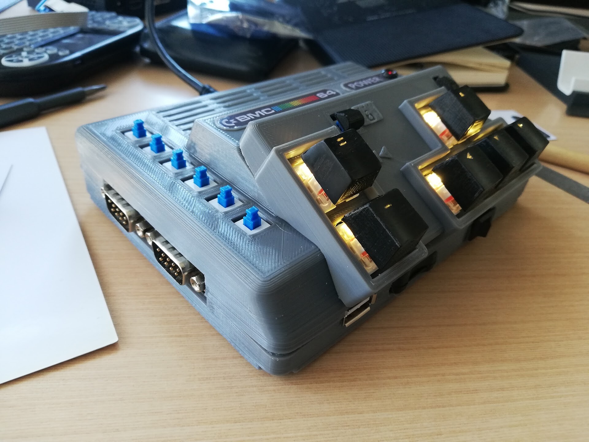
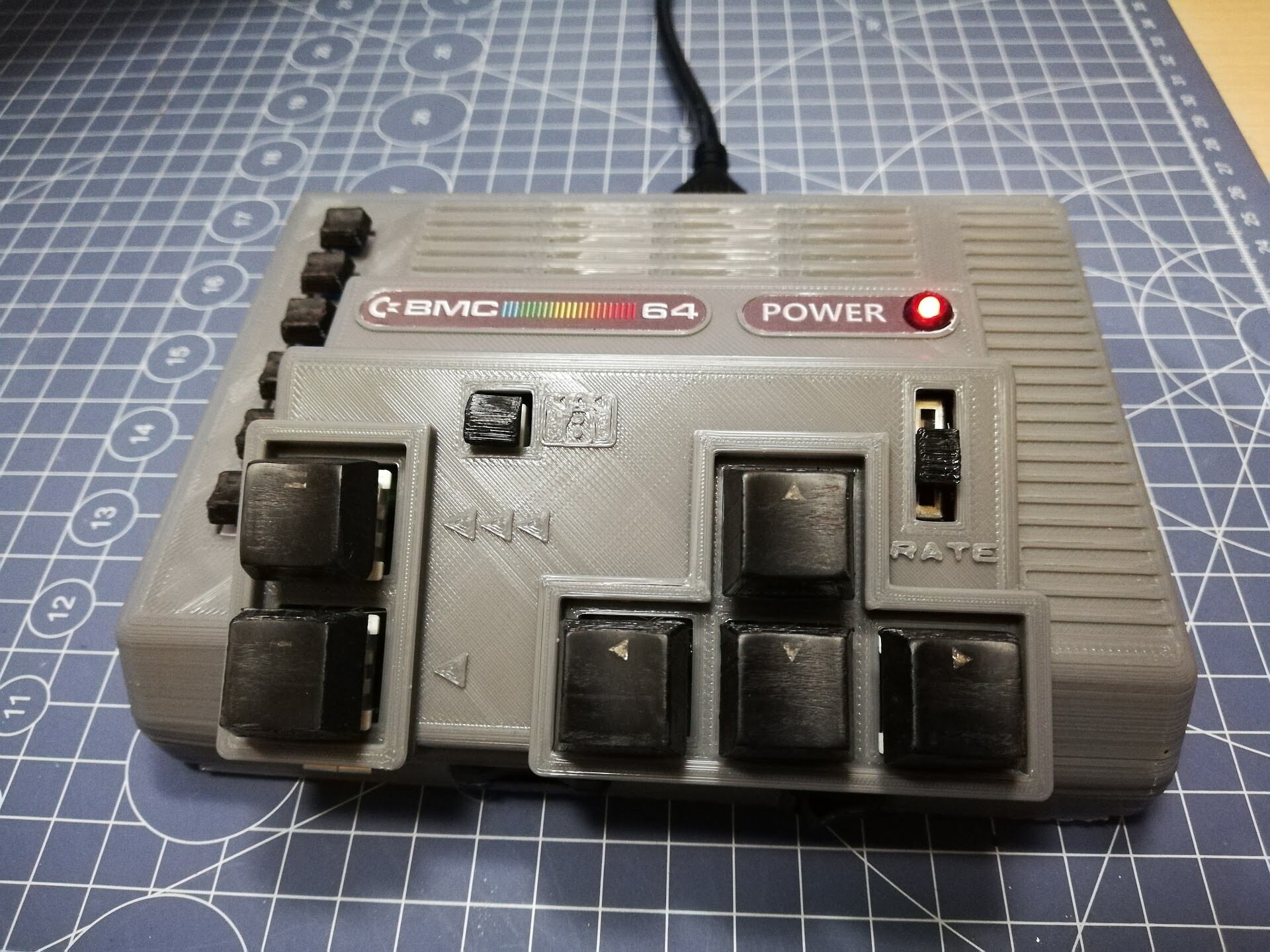
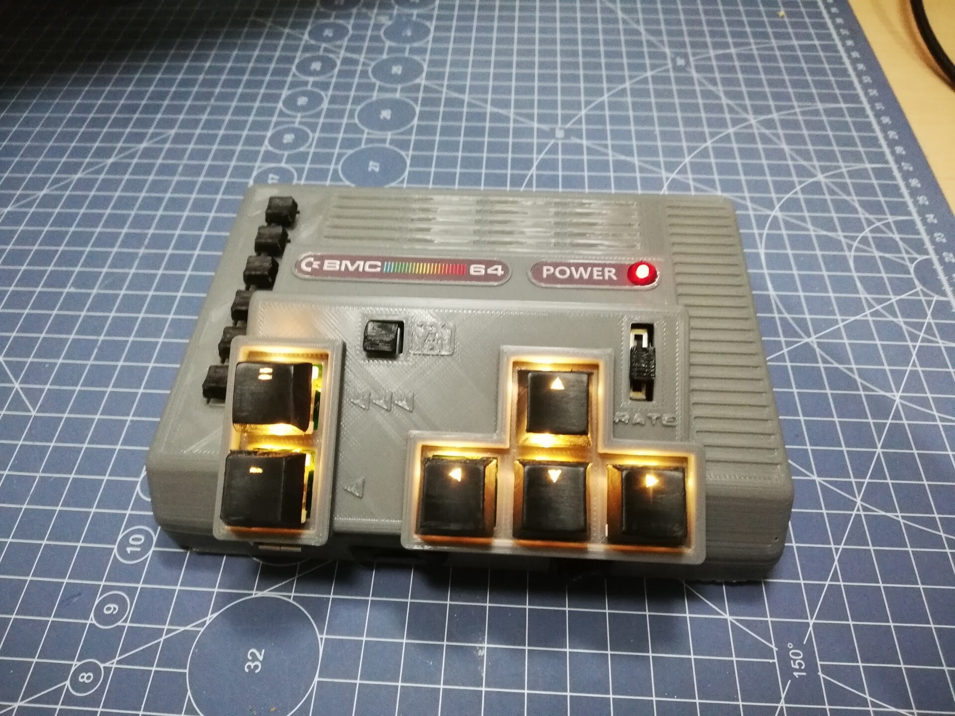
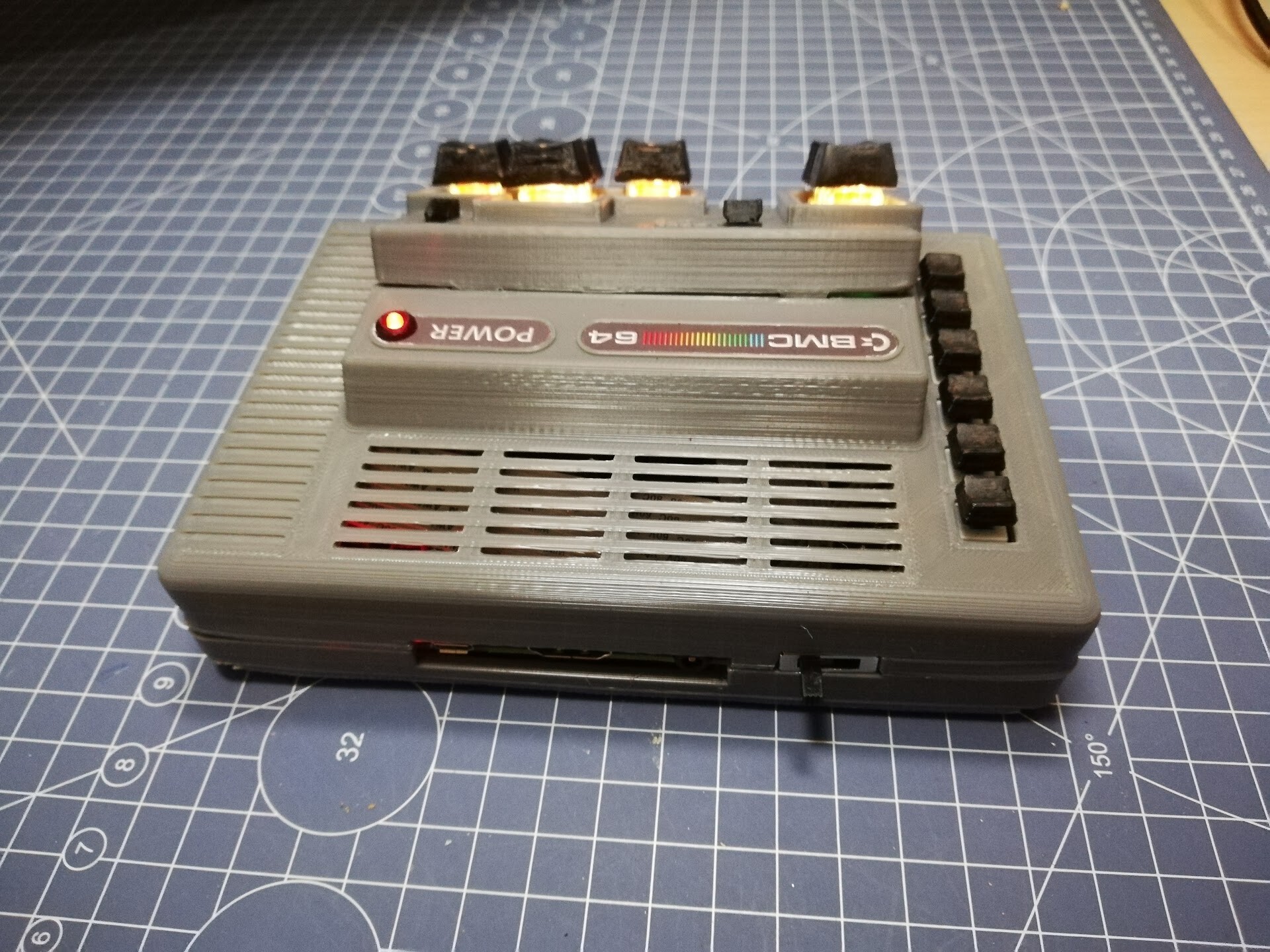
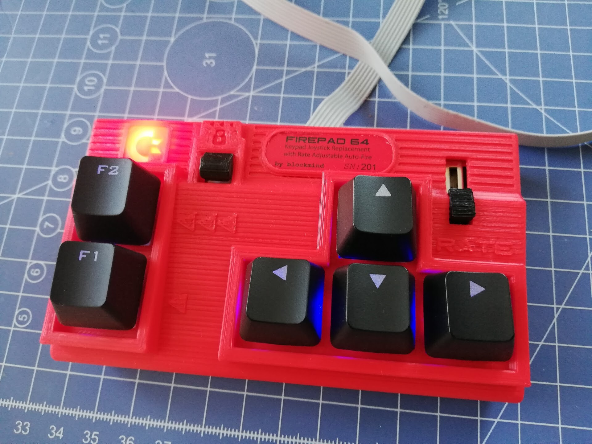
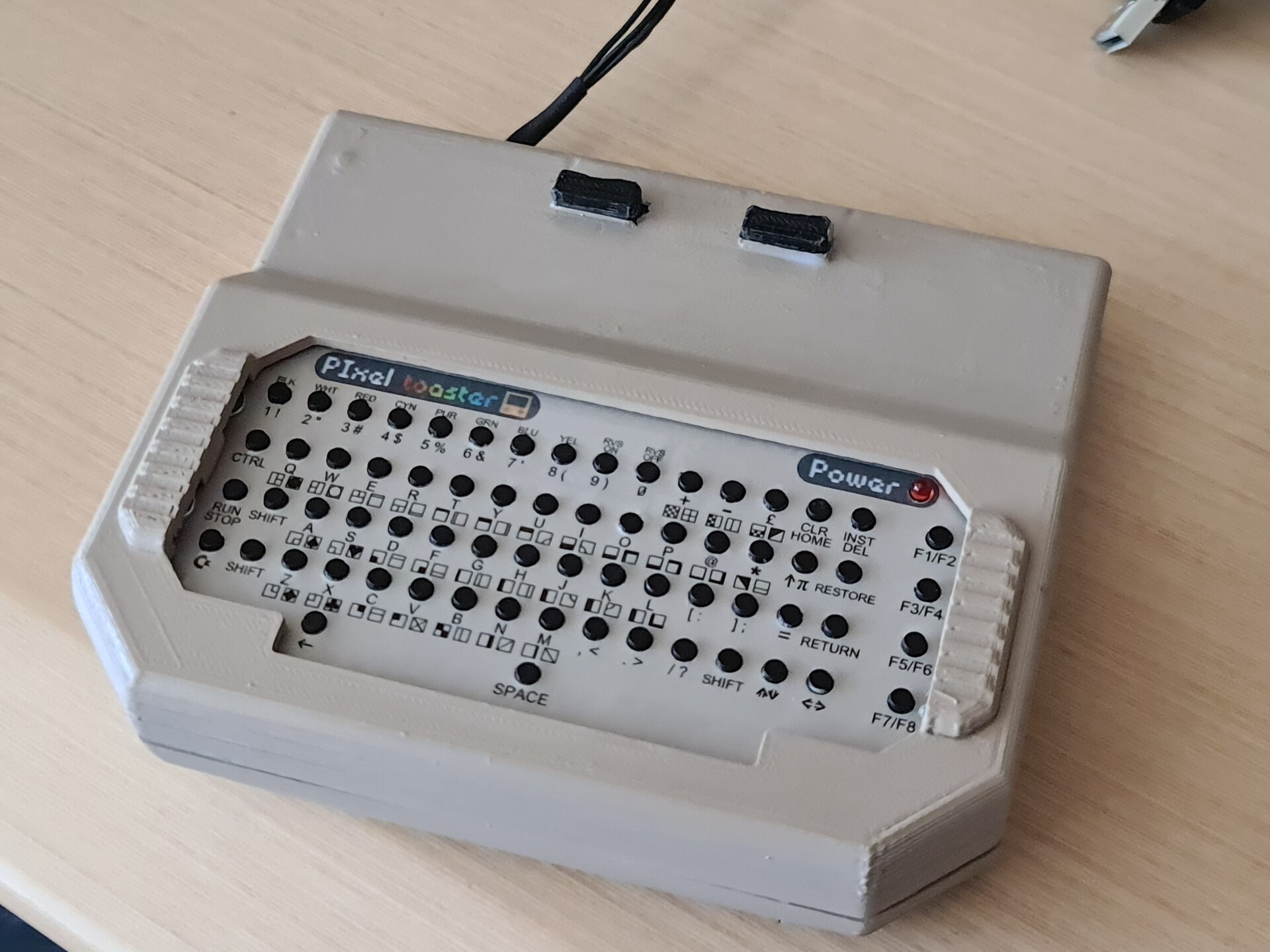
And finally I applied the sticker on top of the faceplate. Very acceptable match!

It looks way better than the white one because of the color match.

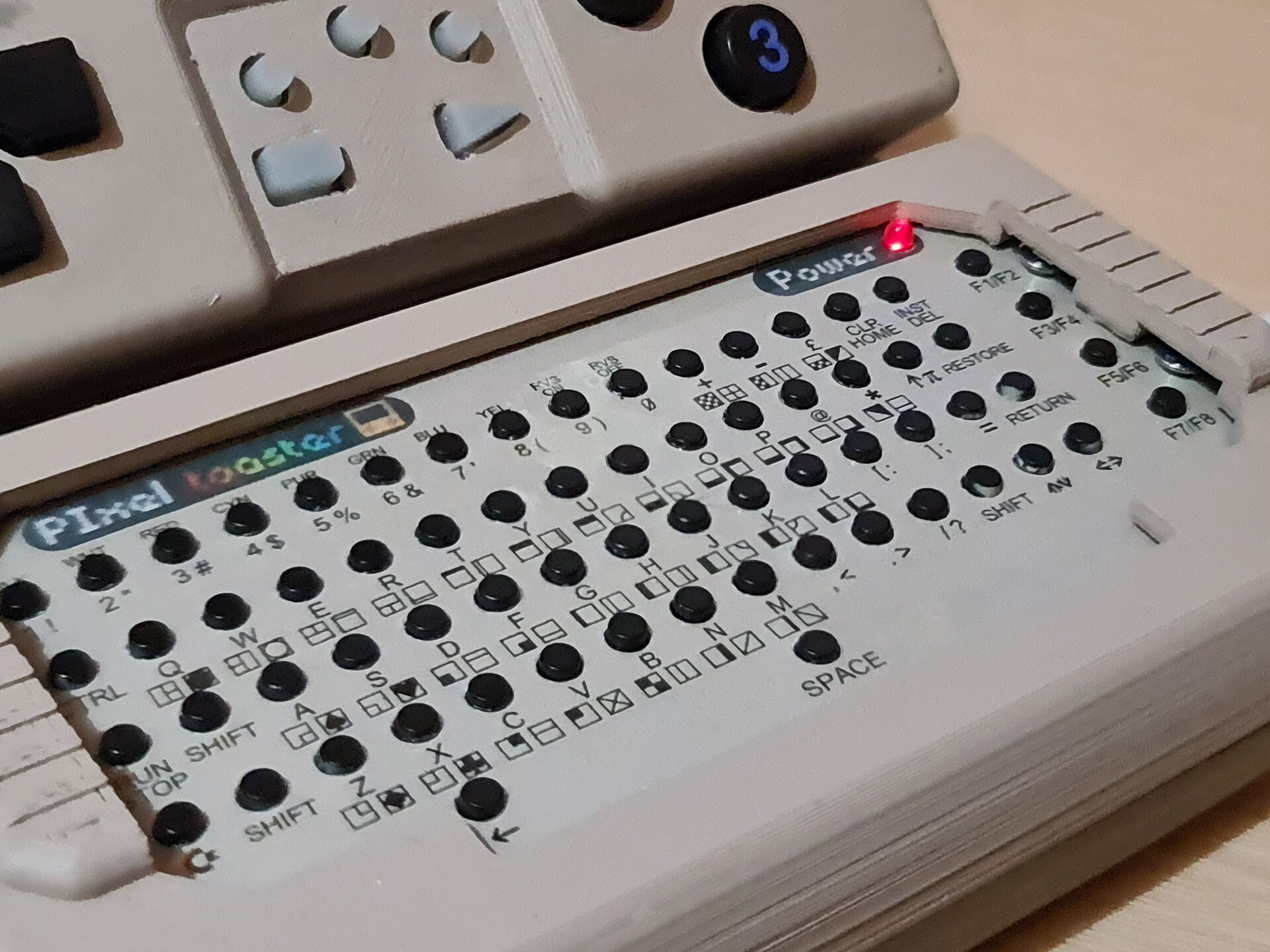
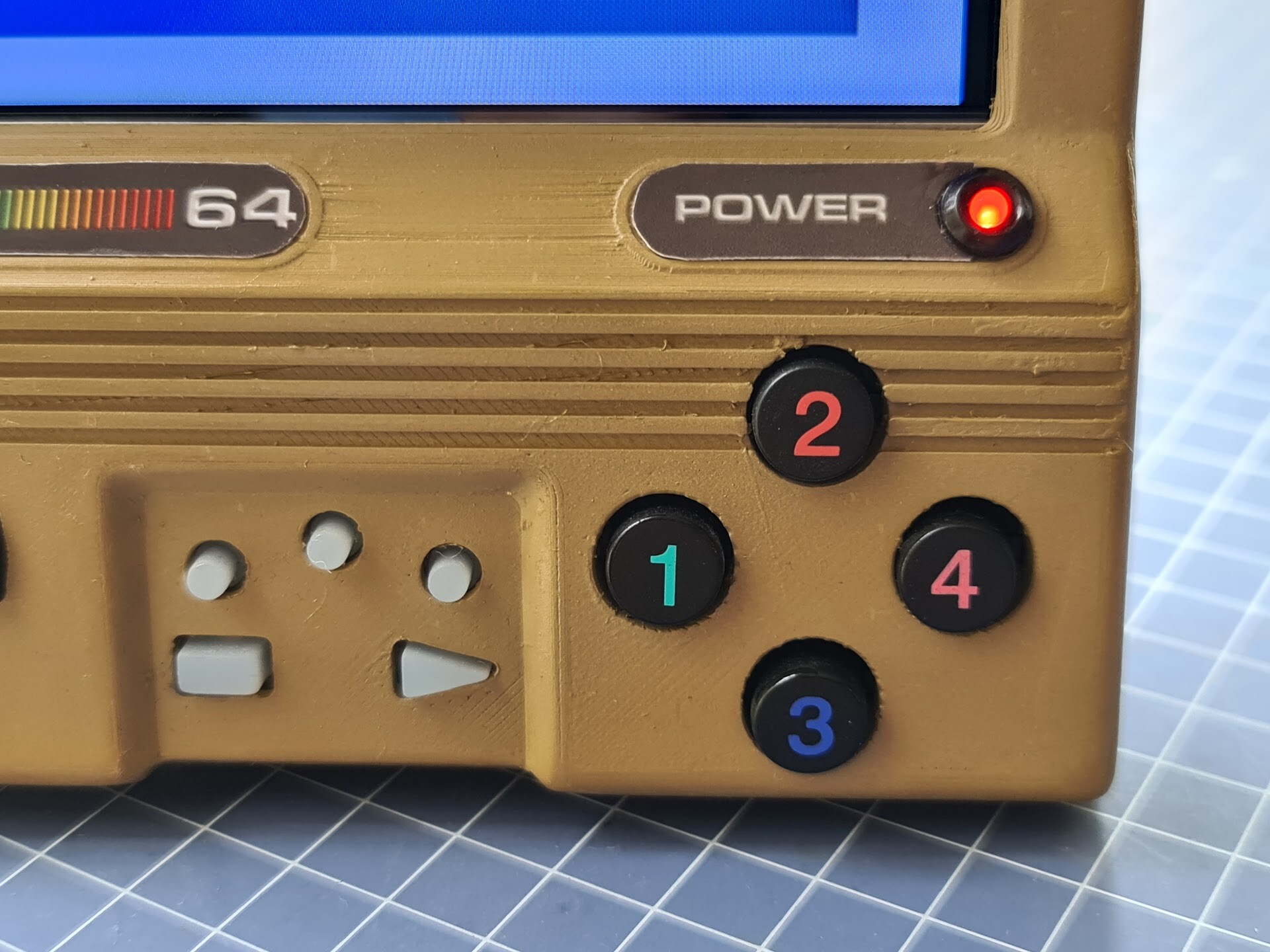
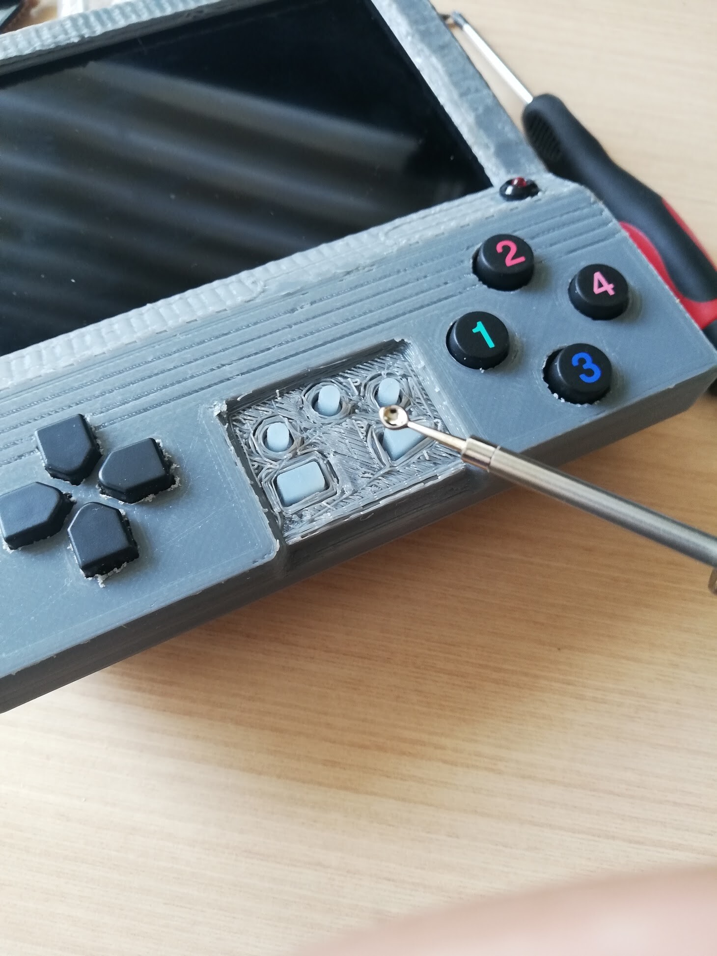
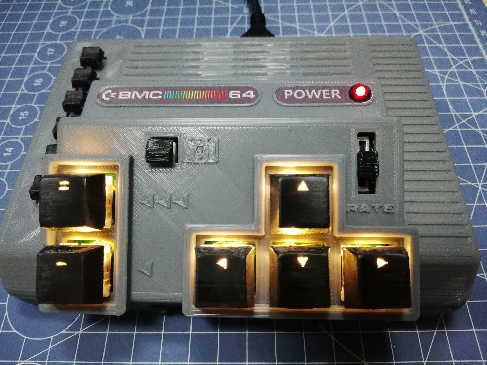
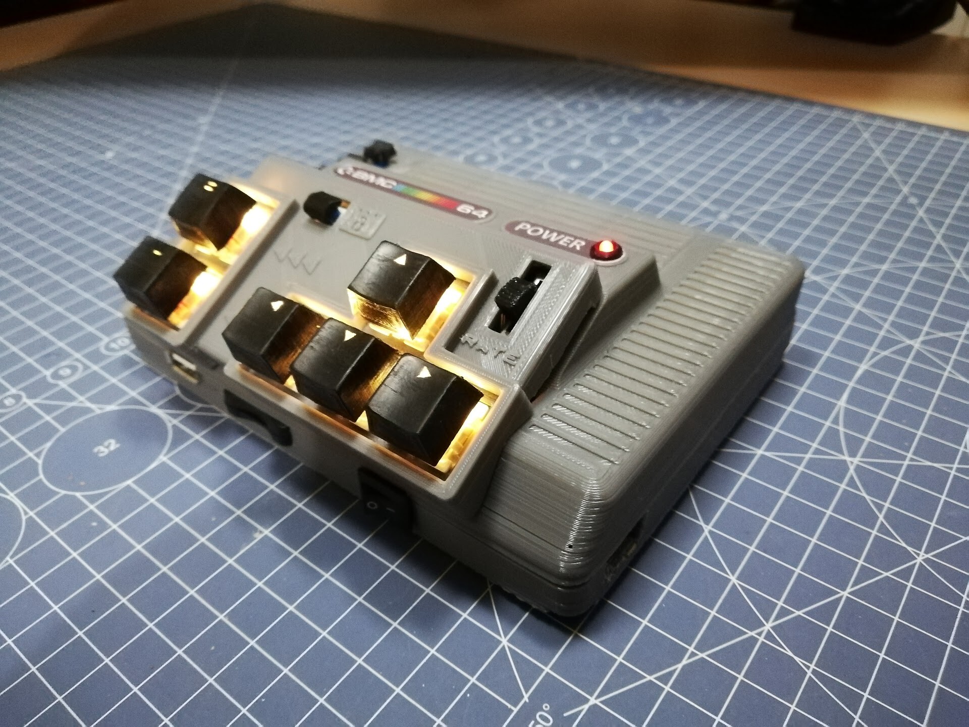
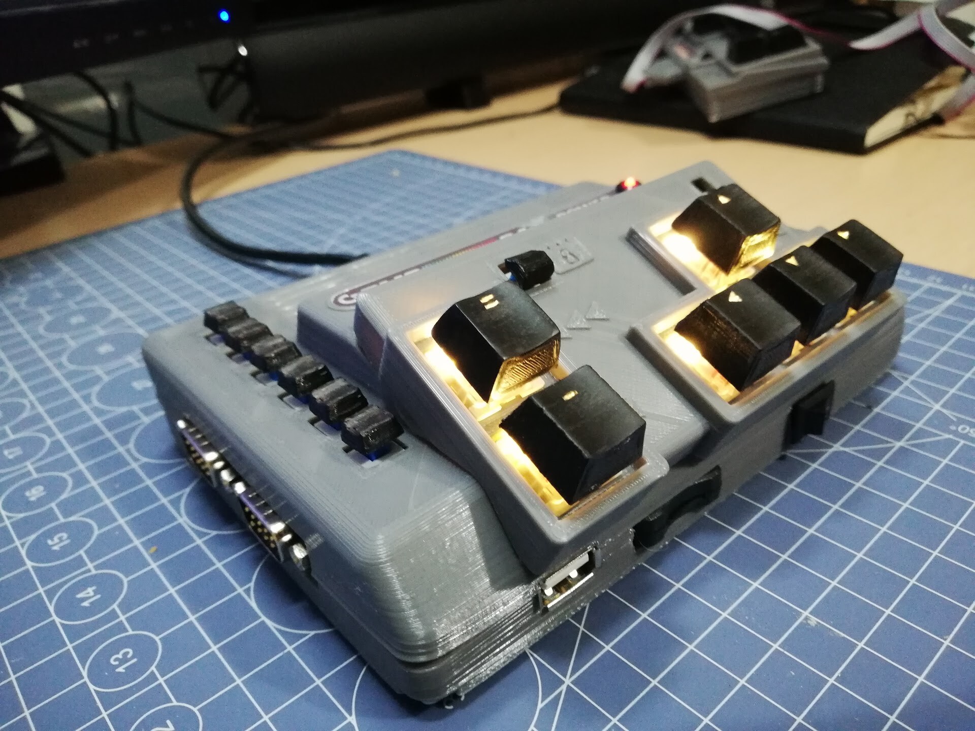
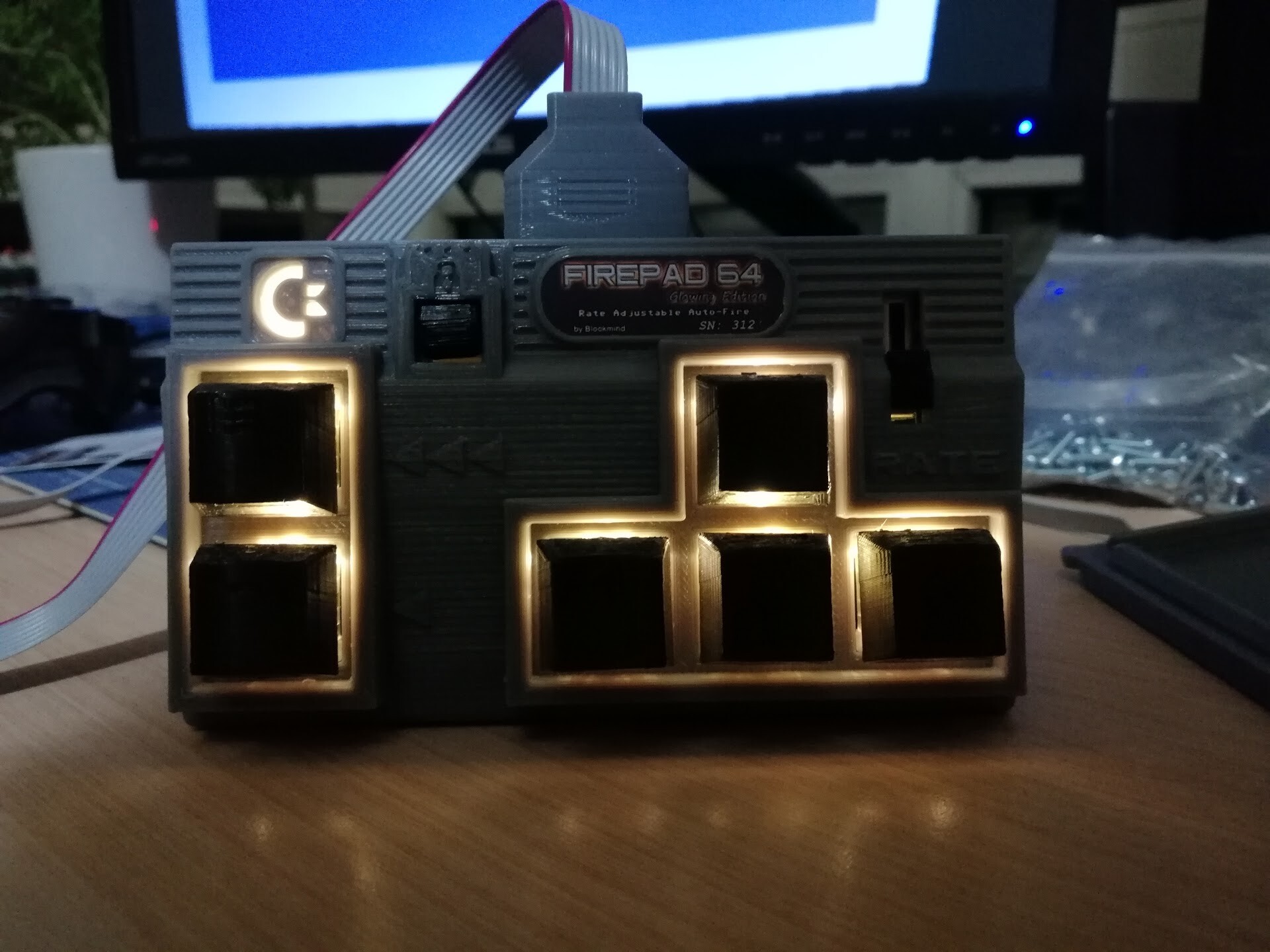
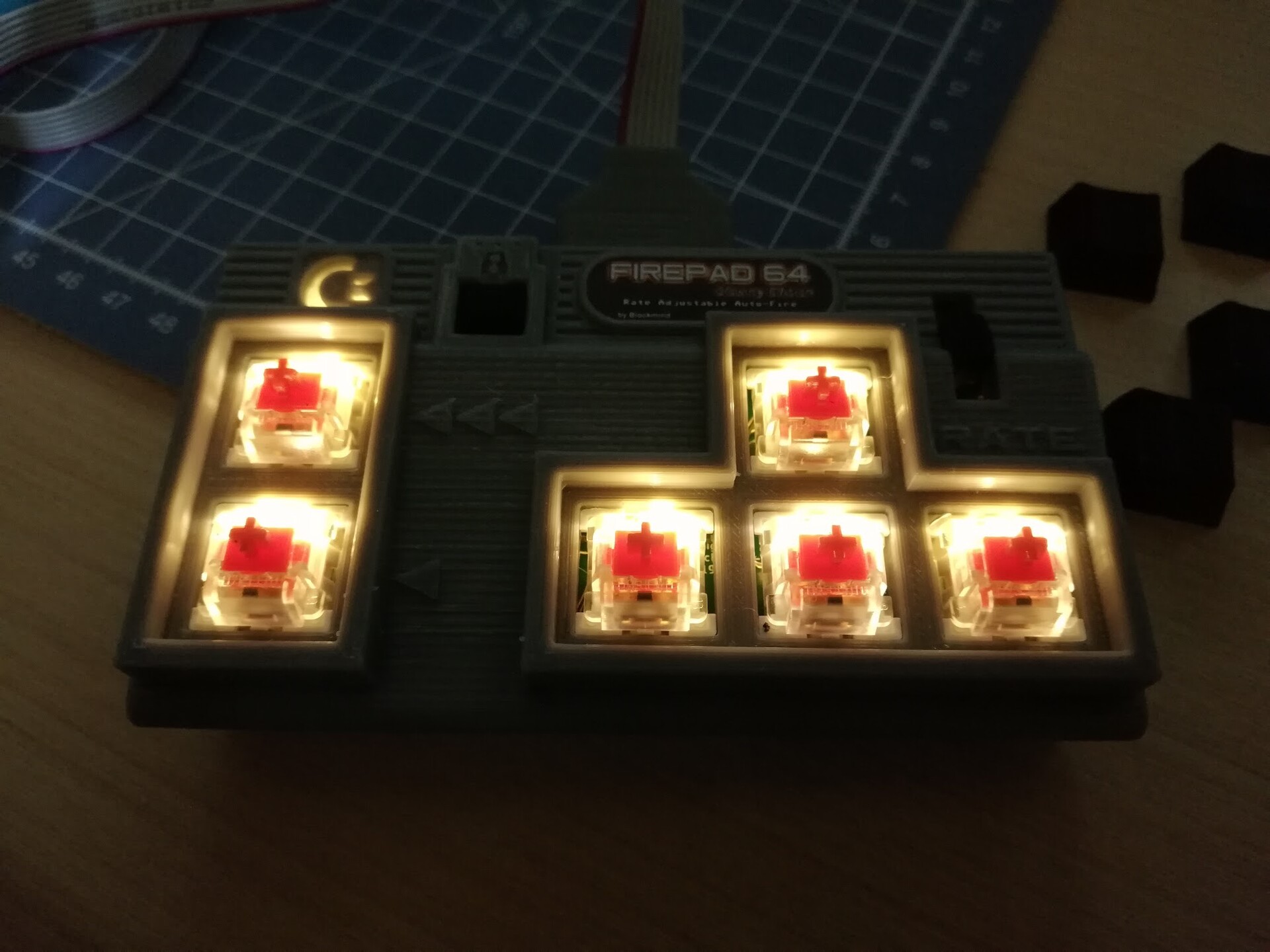
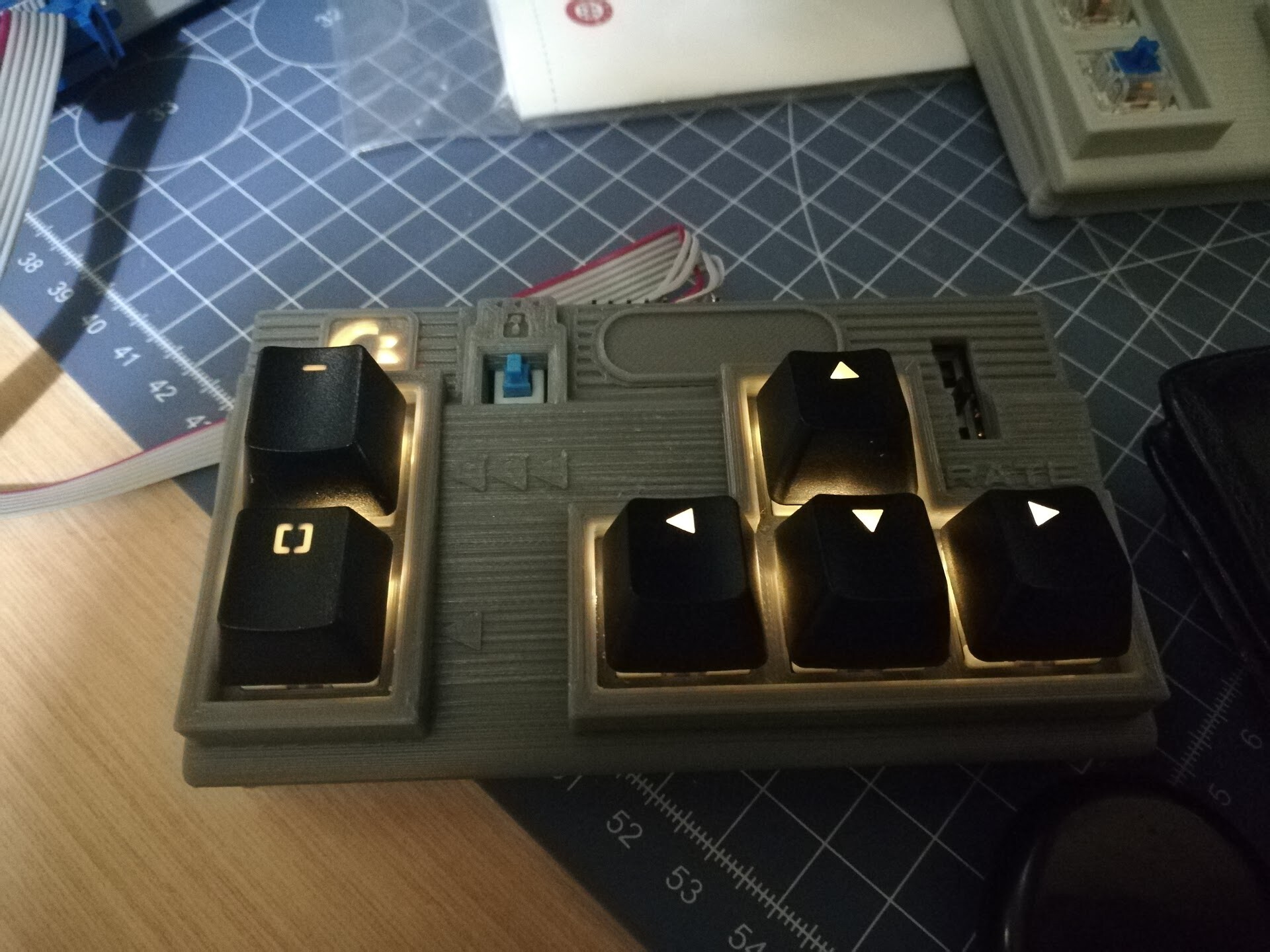
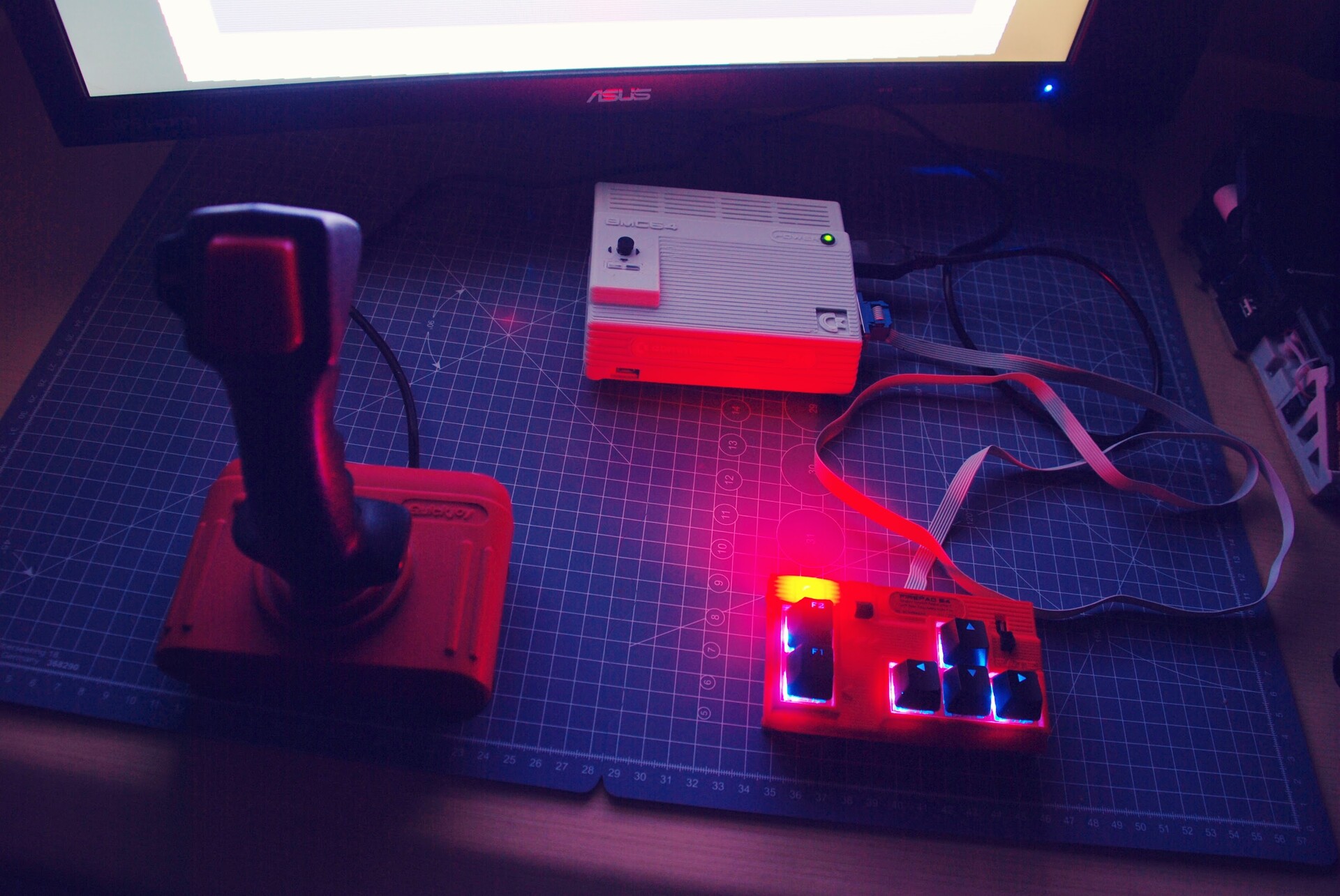
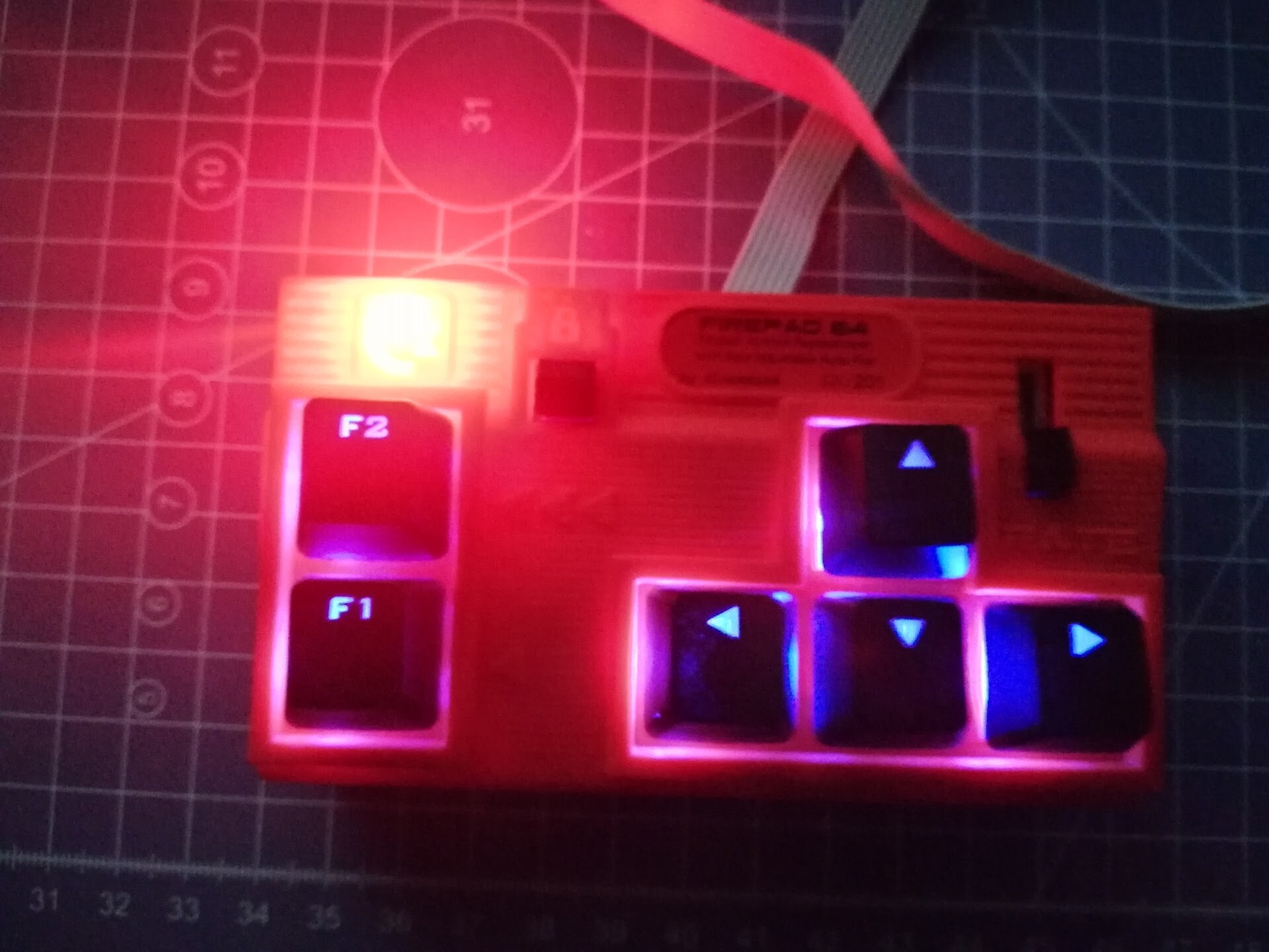
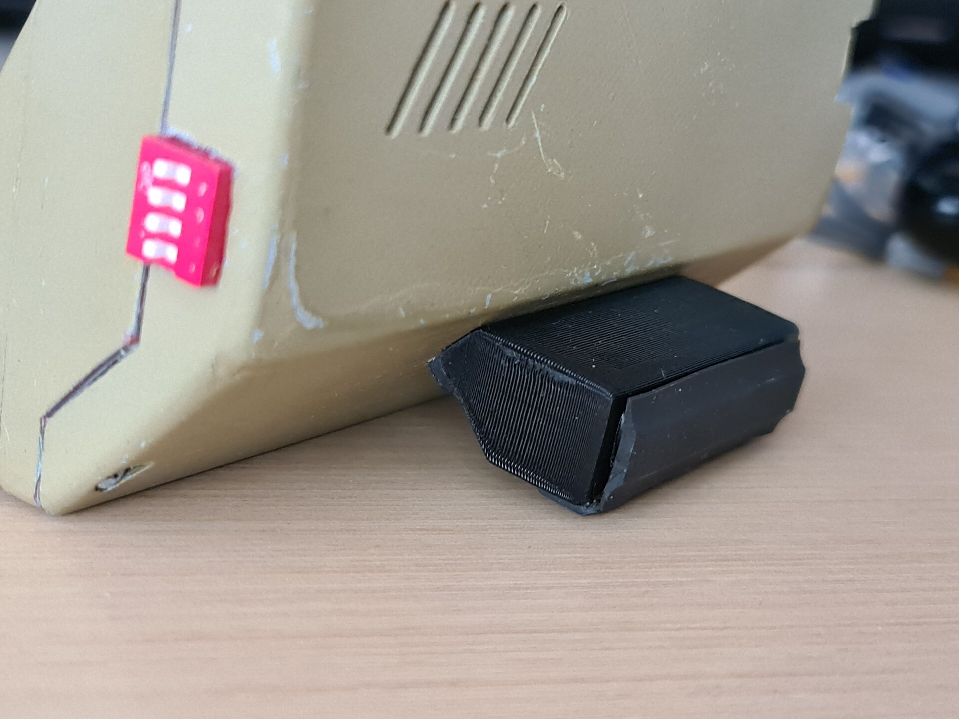
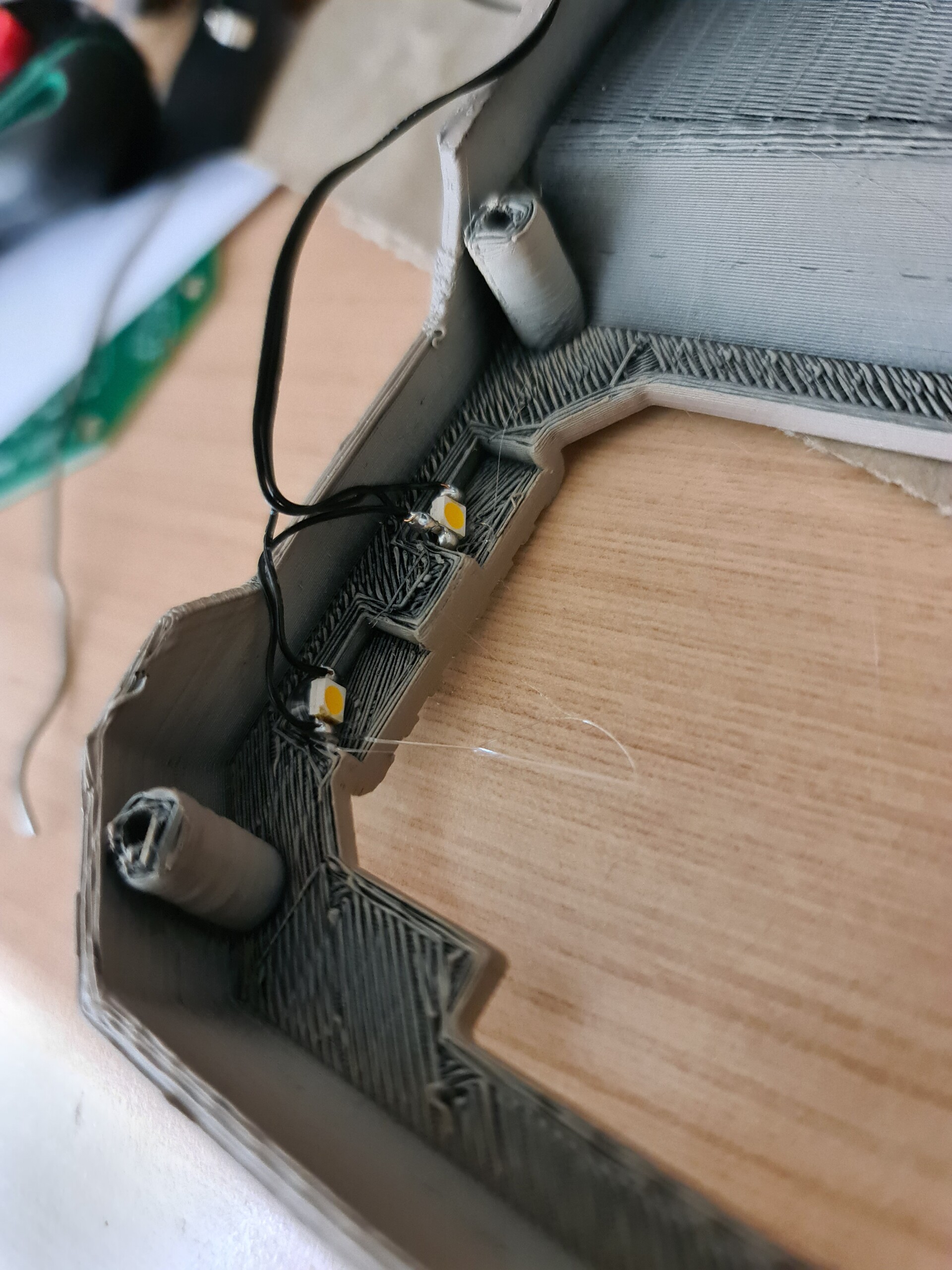
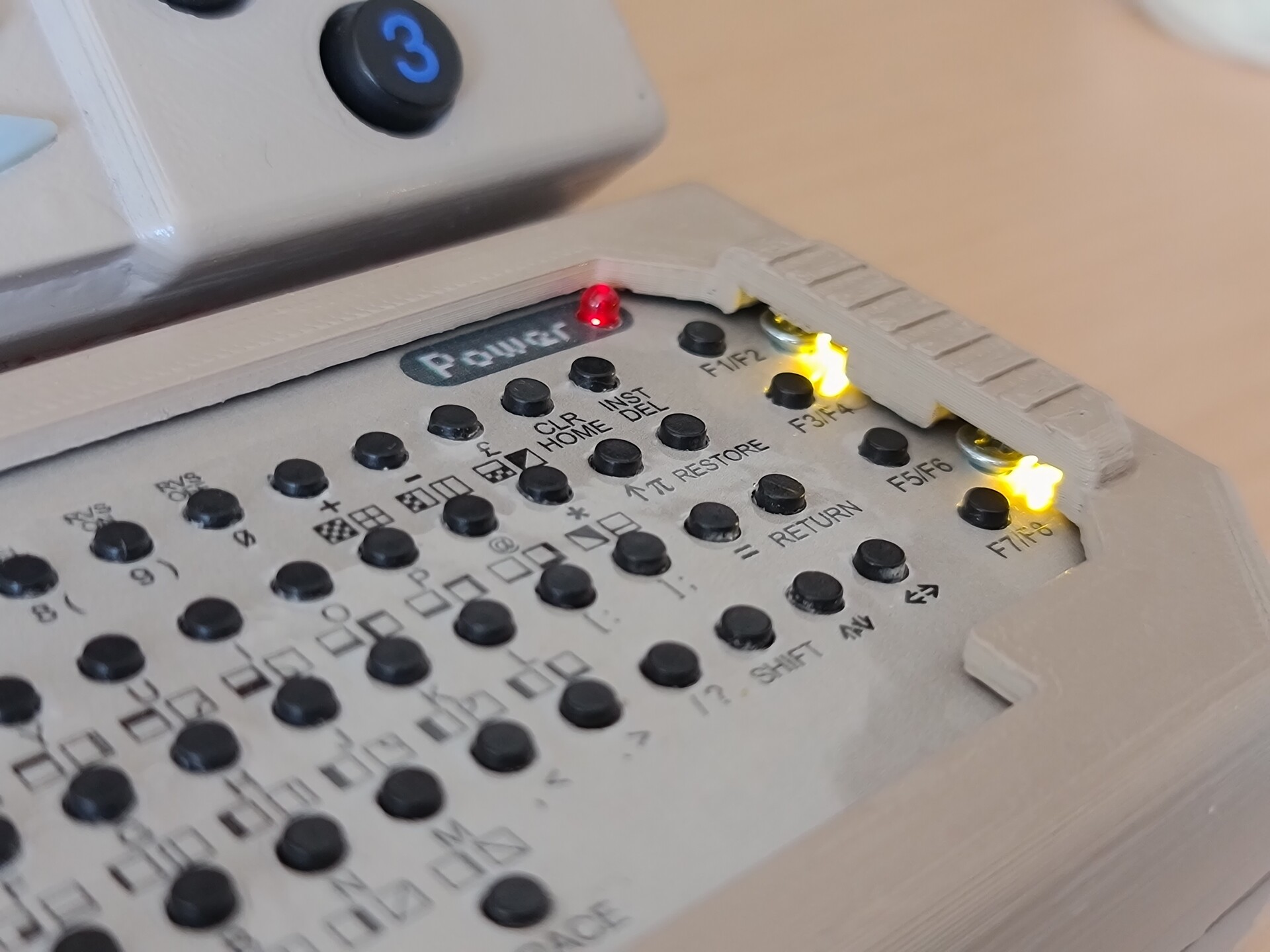
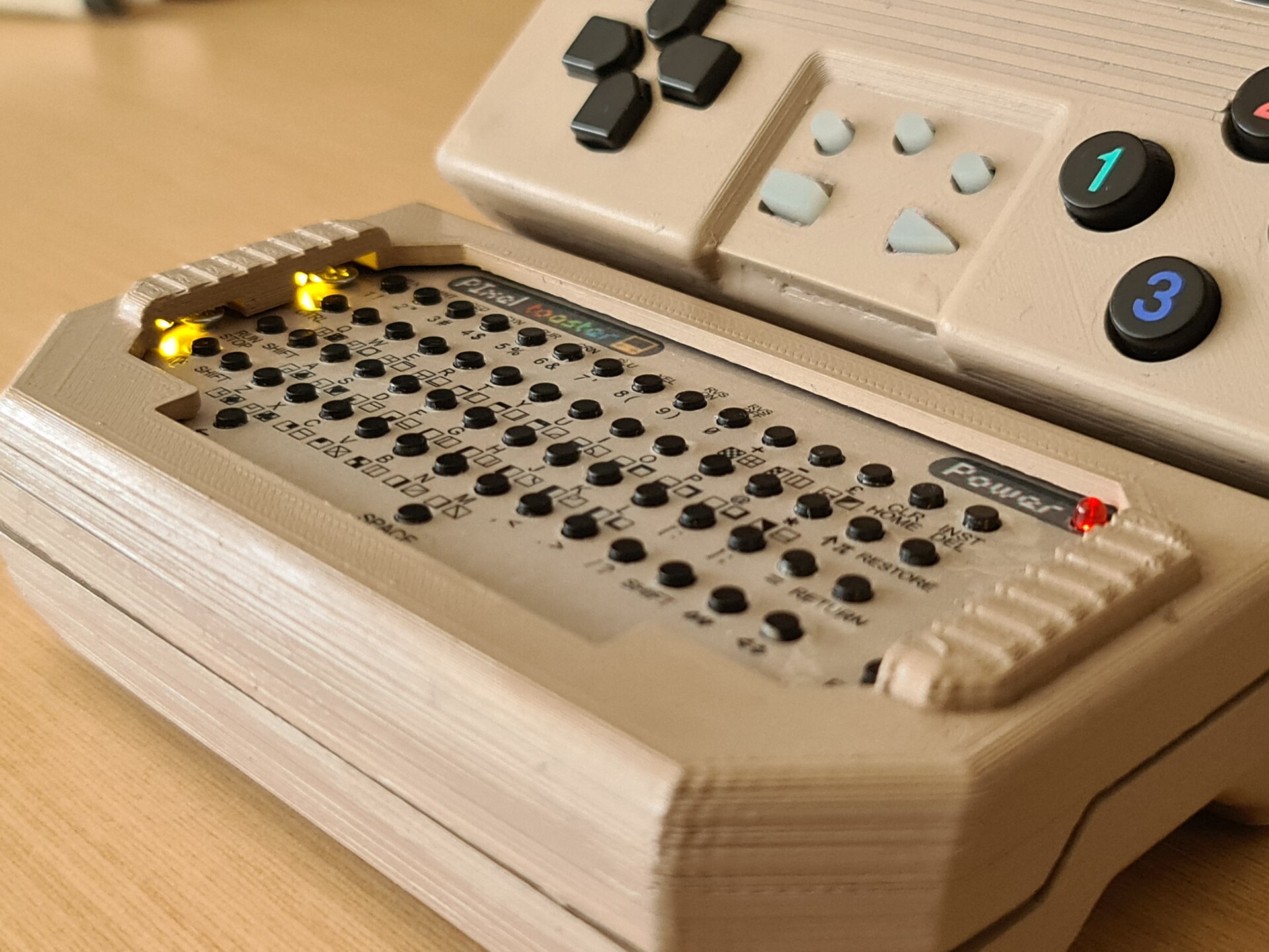
I didn't stop there. My next step was to add some SMD LED lights to the clearance I designed for the screw heads. It lookedlike a perfect placeto add the lights for some decorative key lighting.

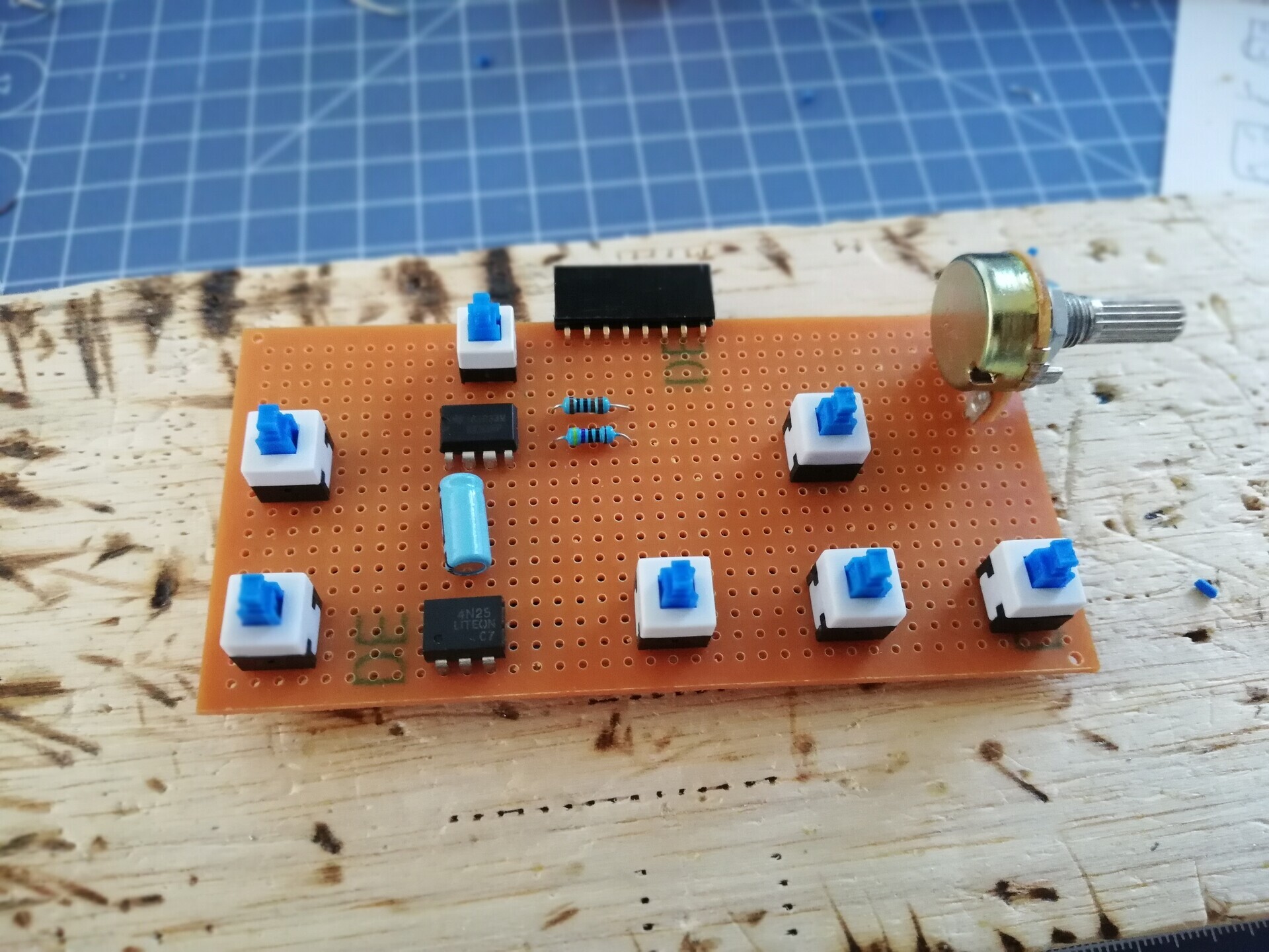
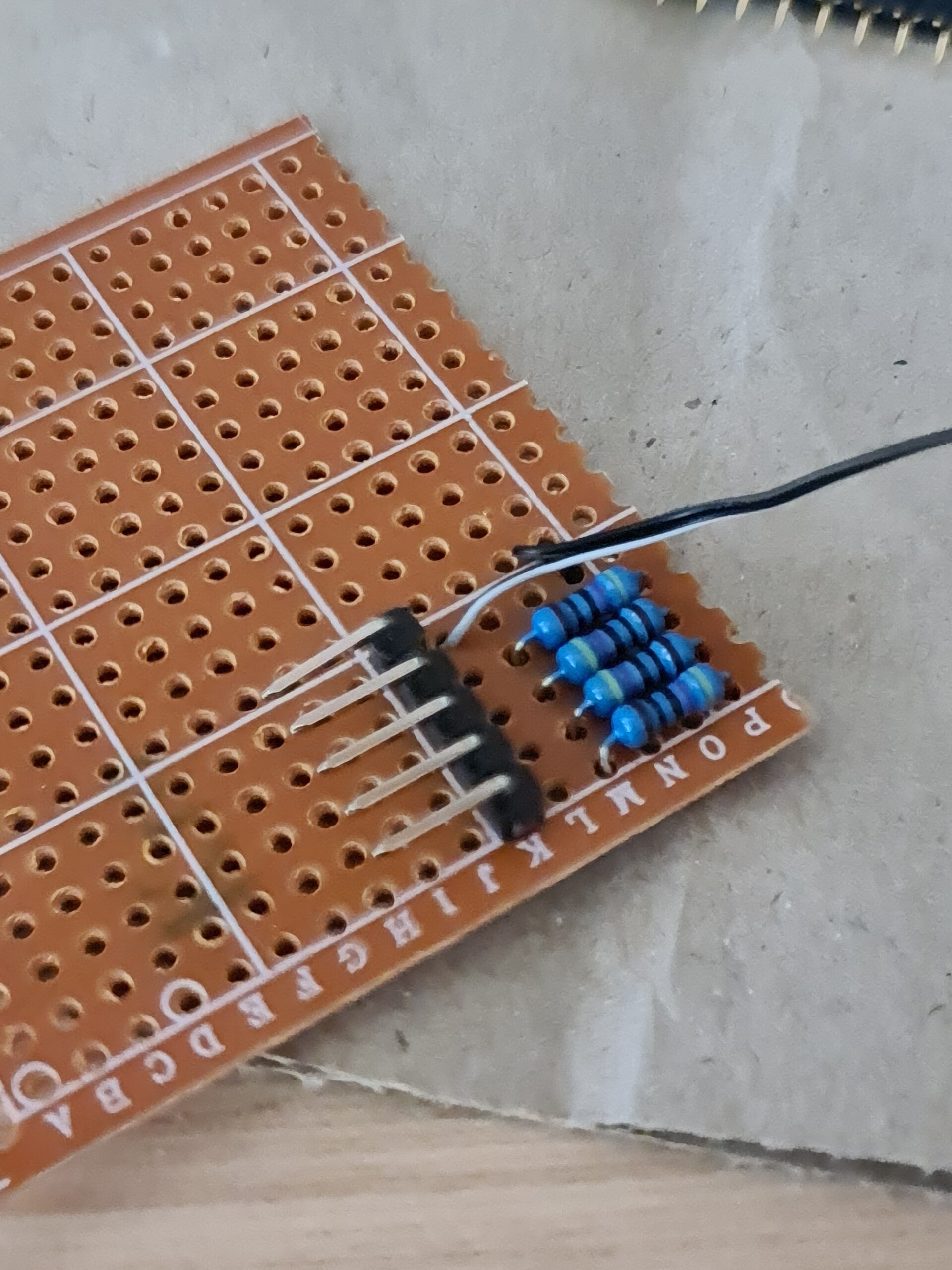
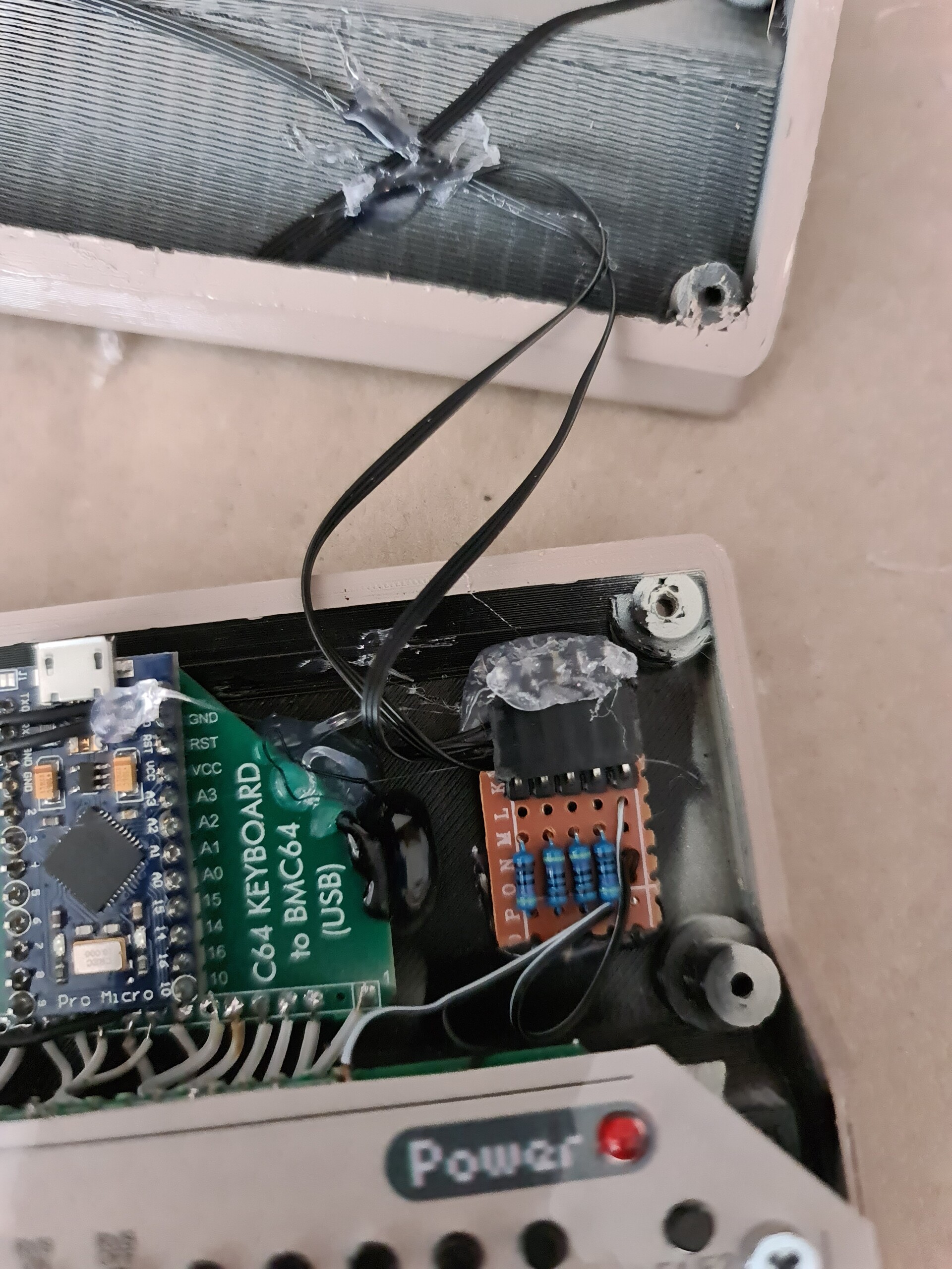
I soldered a simple board for the resistors of the LEDs. I added a 90 degree pins to put a connector, because board is on the bottom part, and the LEDs are on the top part. So I needed to detach LEDs from the bottom part of the case for maintenance purposes.
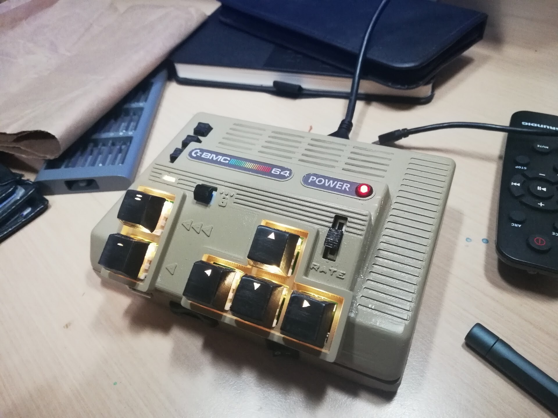
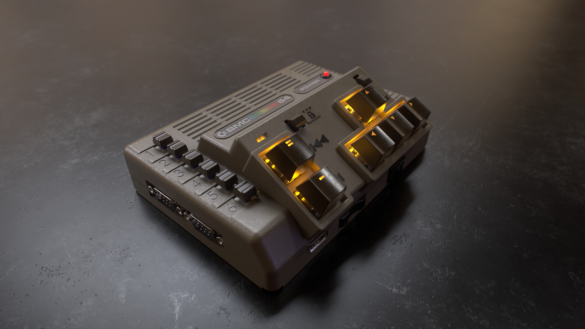
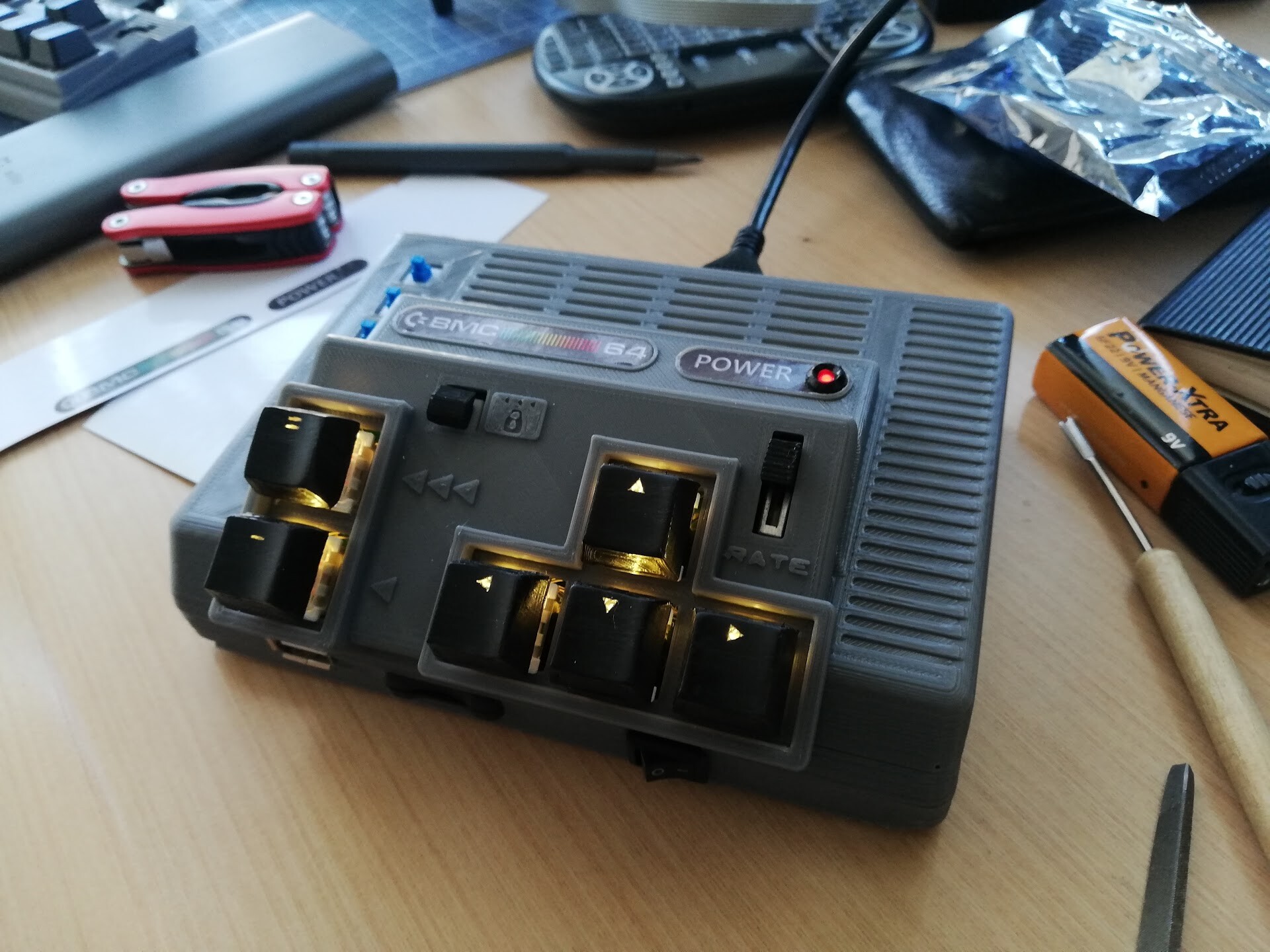
And the lights on!

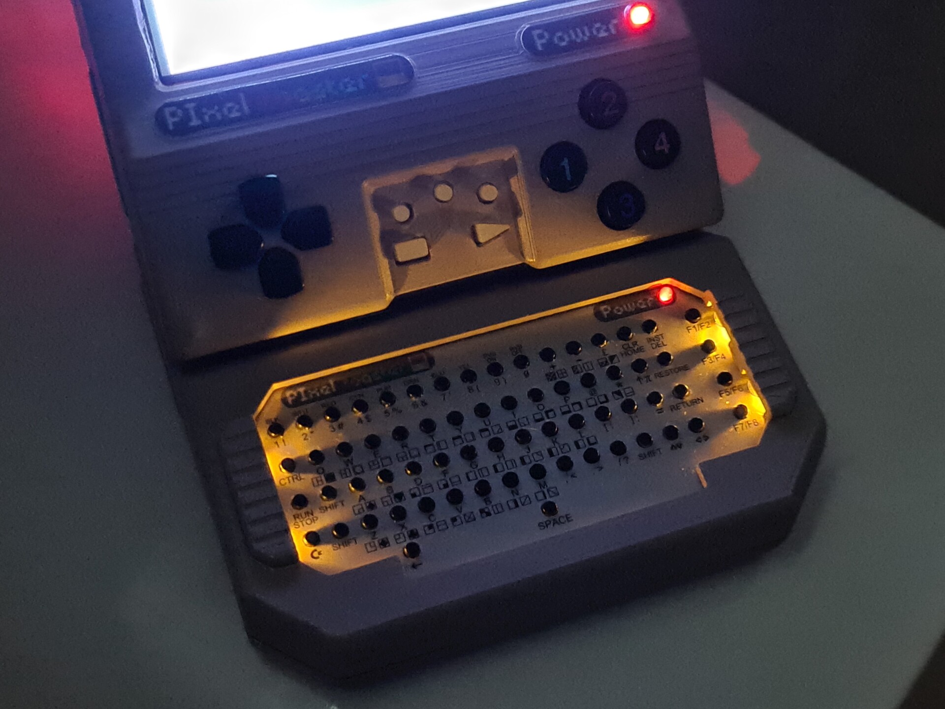
These are not so powerful lights bu they added a nice touch I suppose.

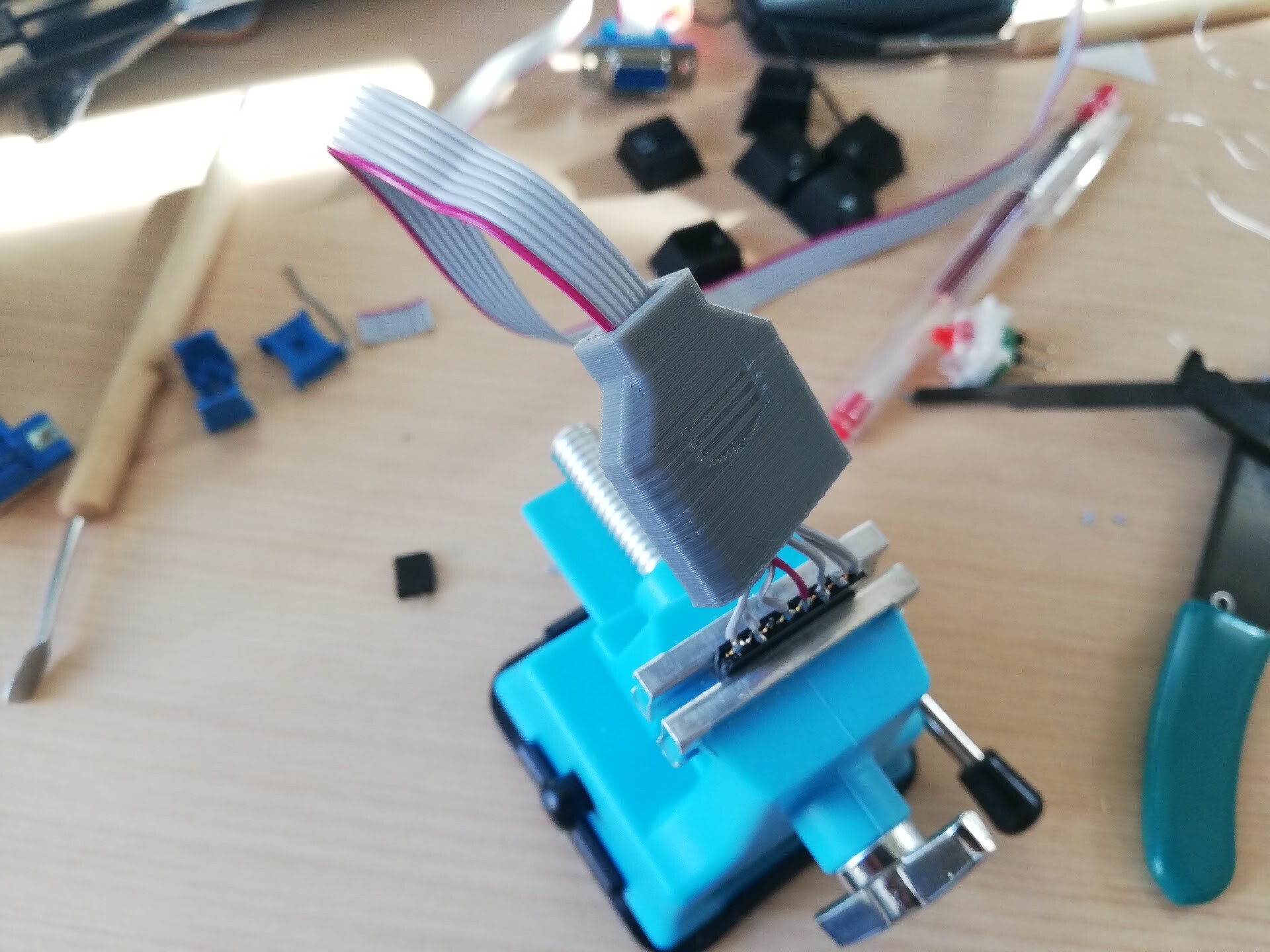
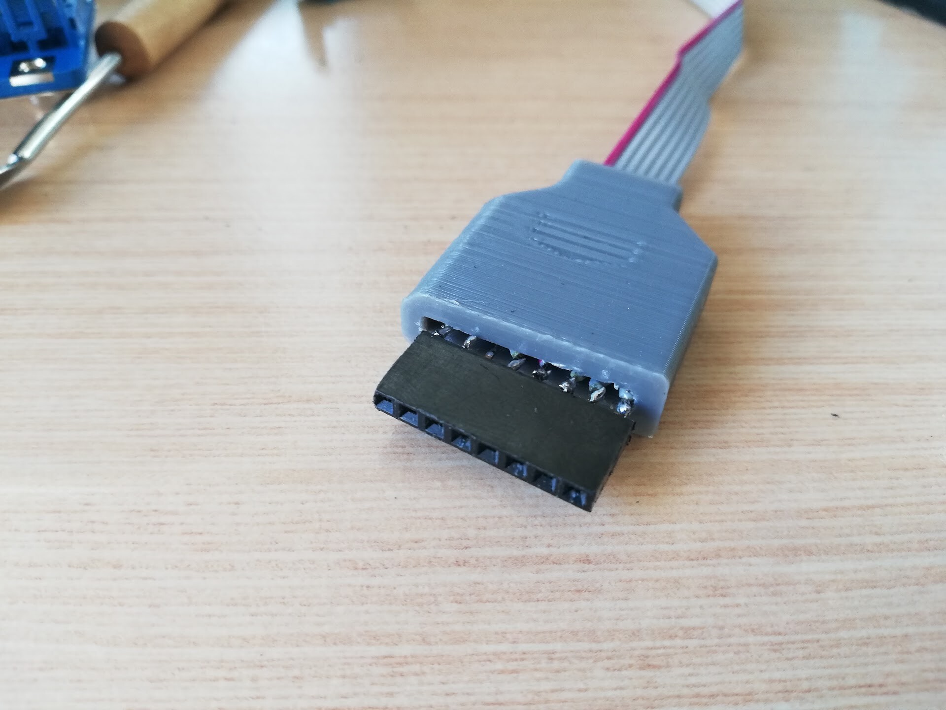
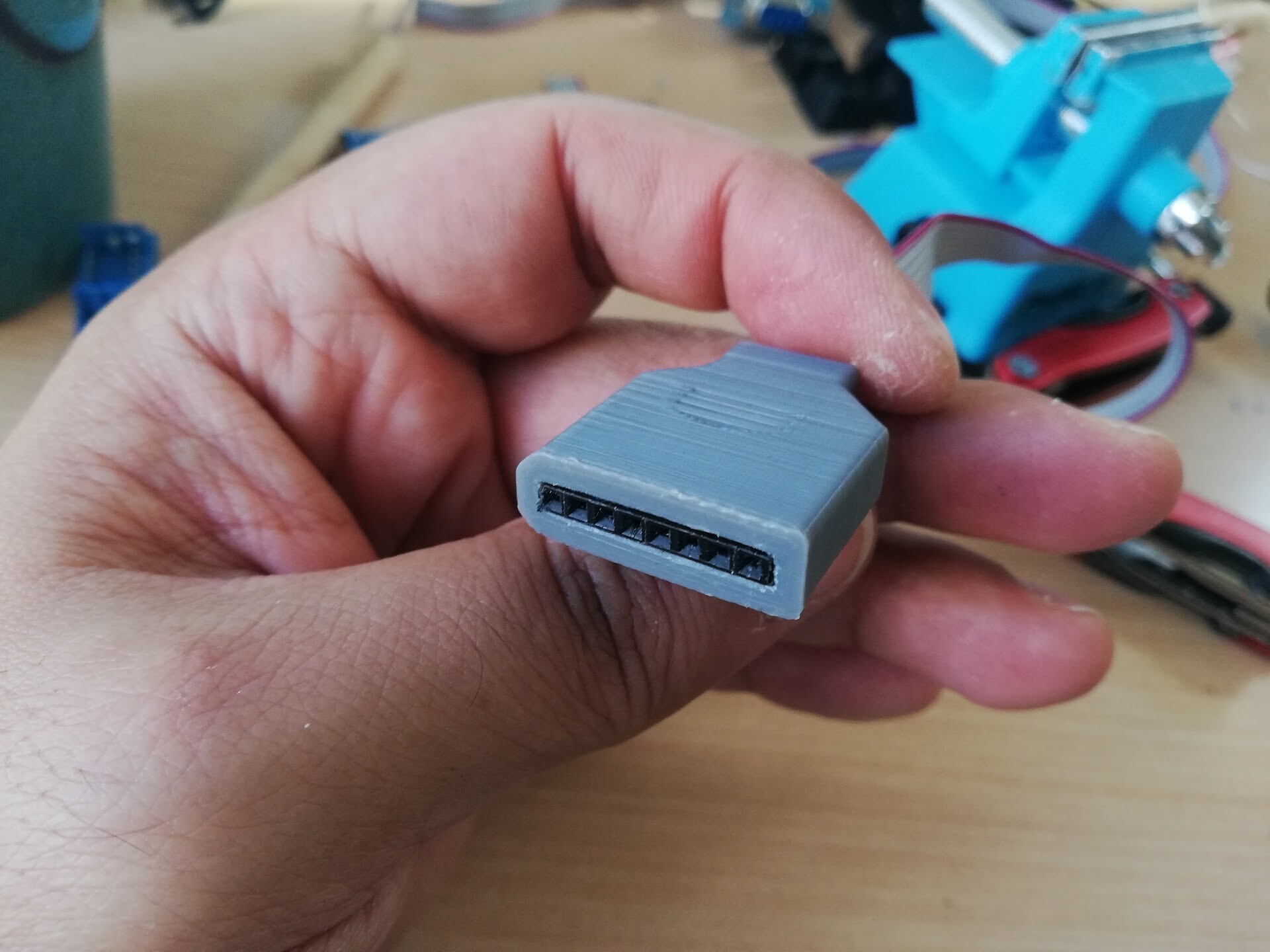
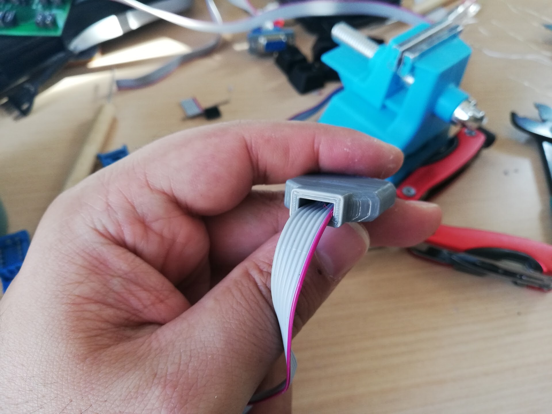
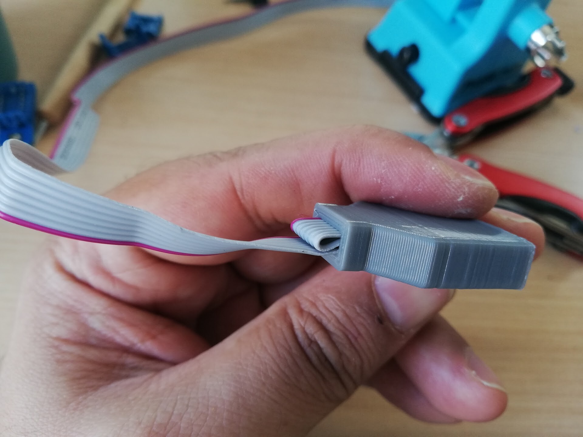
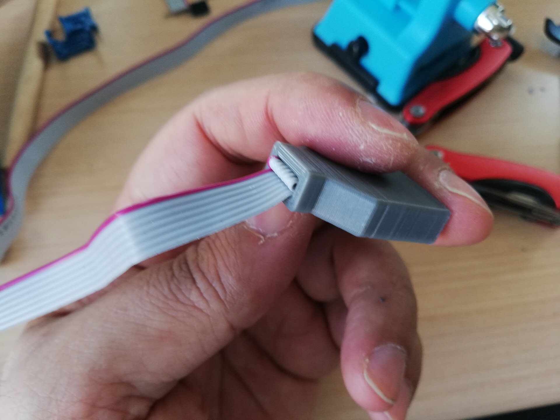
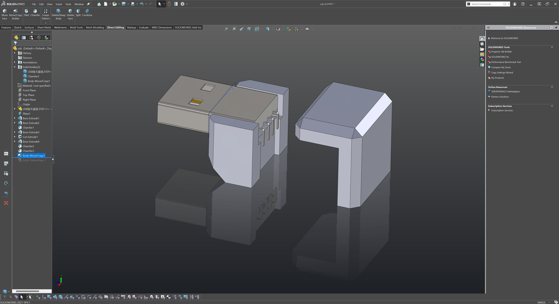
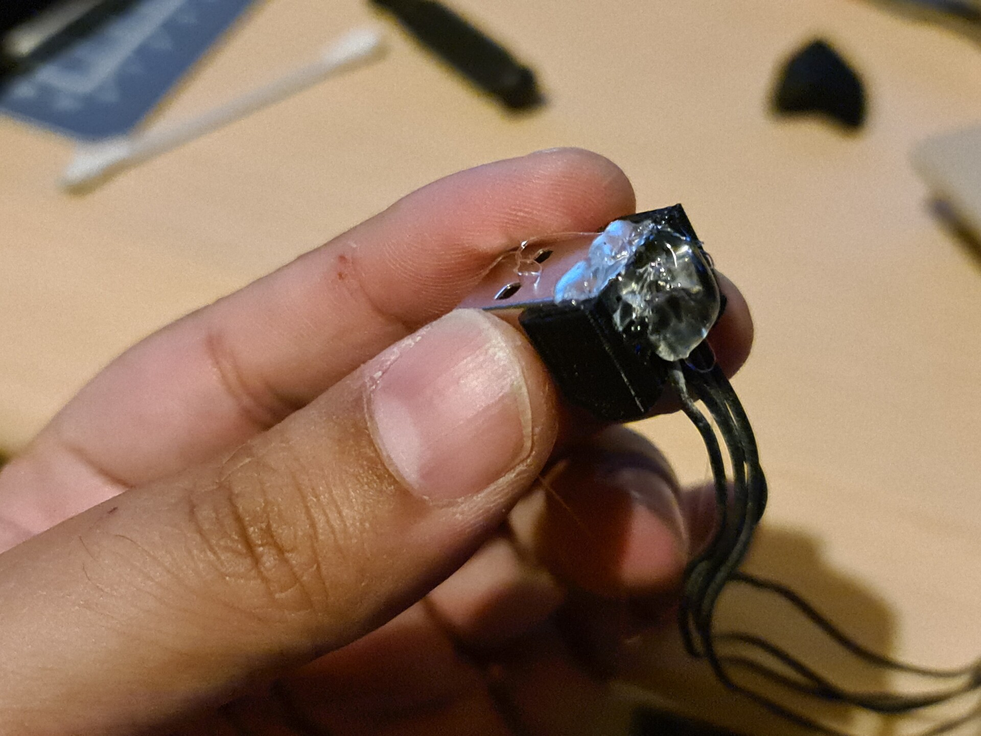
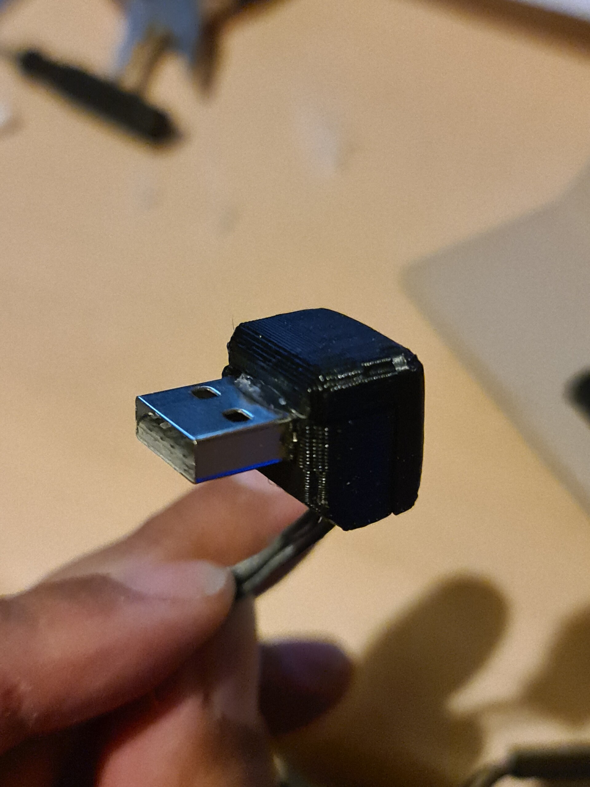
For the USB connector, I made up a case like this. I know it's not looking so good but at least it secured the soldier and cables on the tip.

Because of the bad masking decision I made, the bottom keyboard module was looking like this:

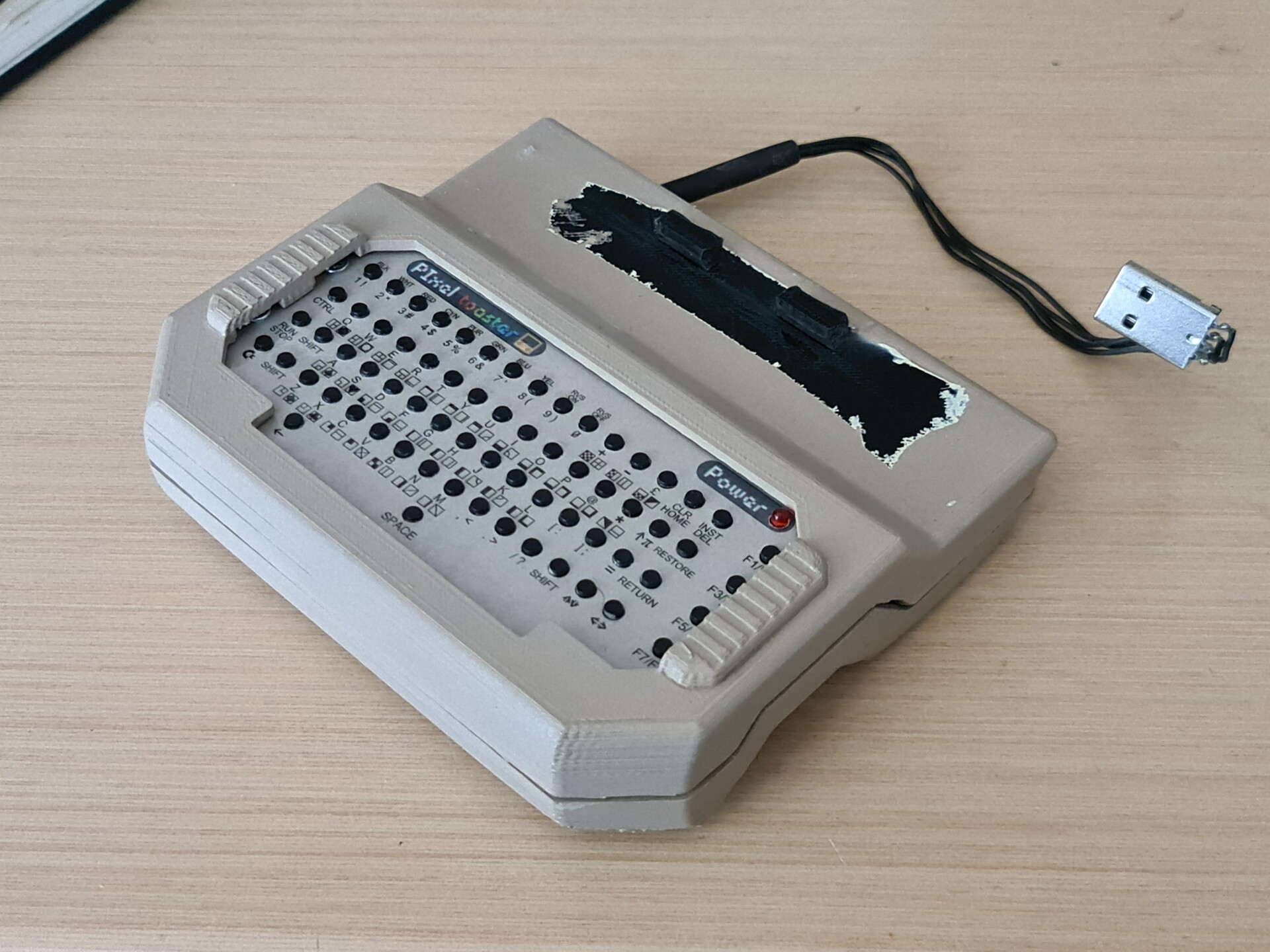
I kept that black are masked because it is the attachment hooks. Painting them will cause losing tolerances on the shrink fit. But it looks terrible this way and even it's not exposed after attaching to the screen, I wouldn't let it be like that. So I re-painted that area. But as you can see, there was an height level variation between the first paint and the secondary paint surfaces.

I sand papered it and painted one last time and it's done!

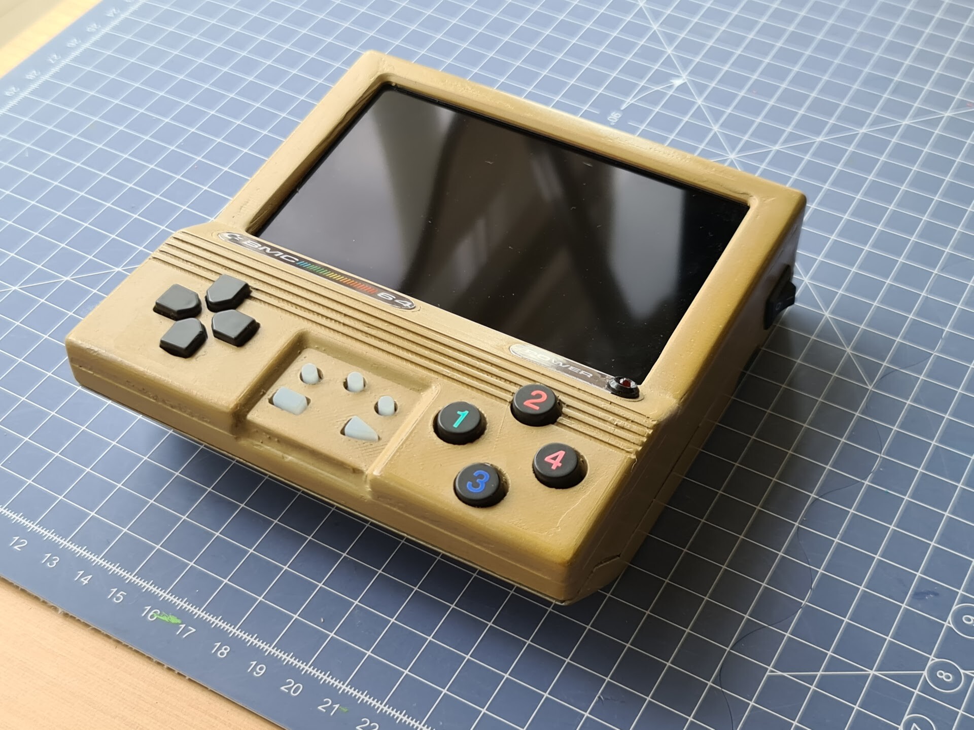
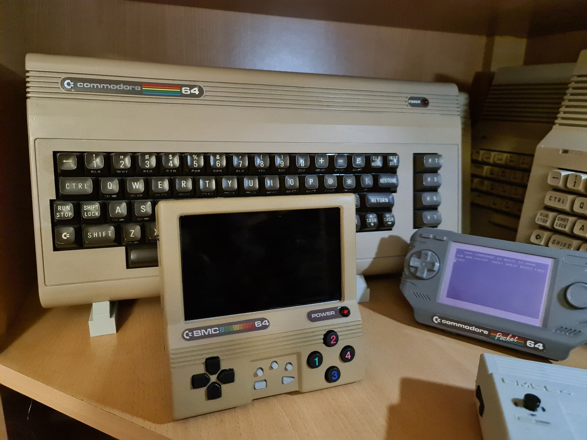
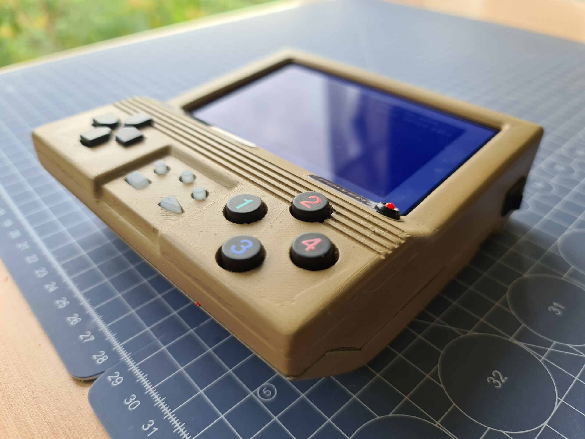
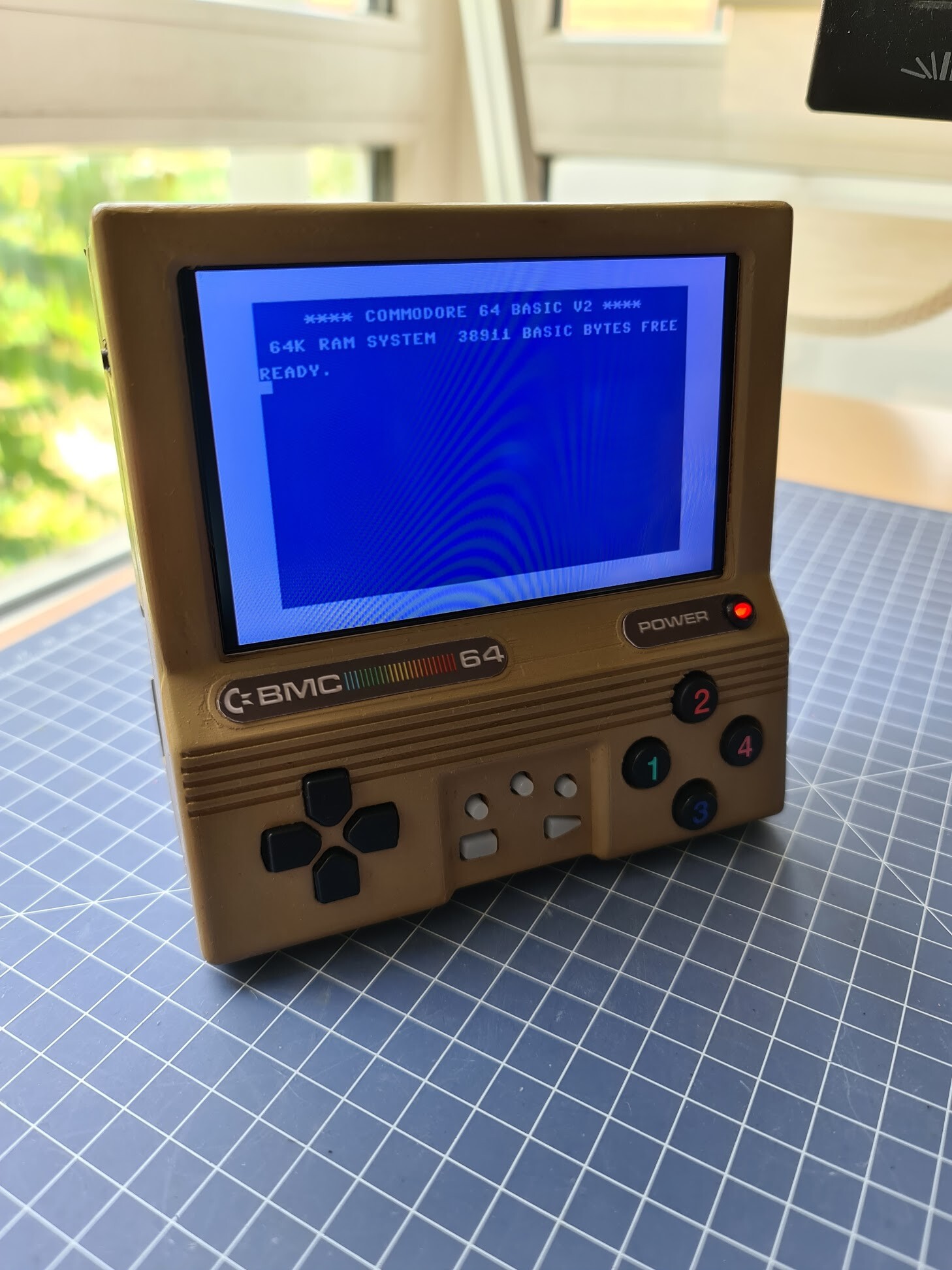
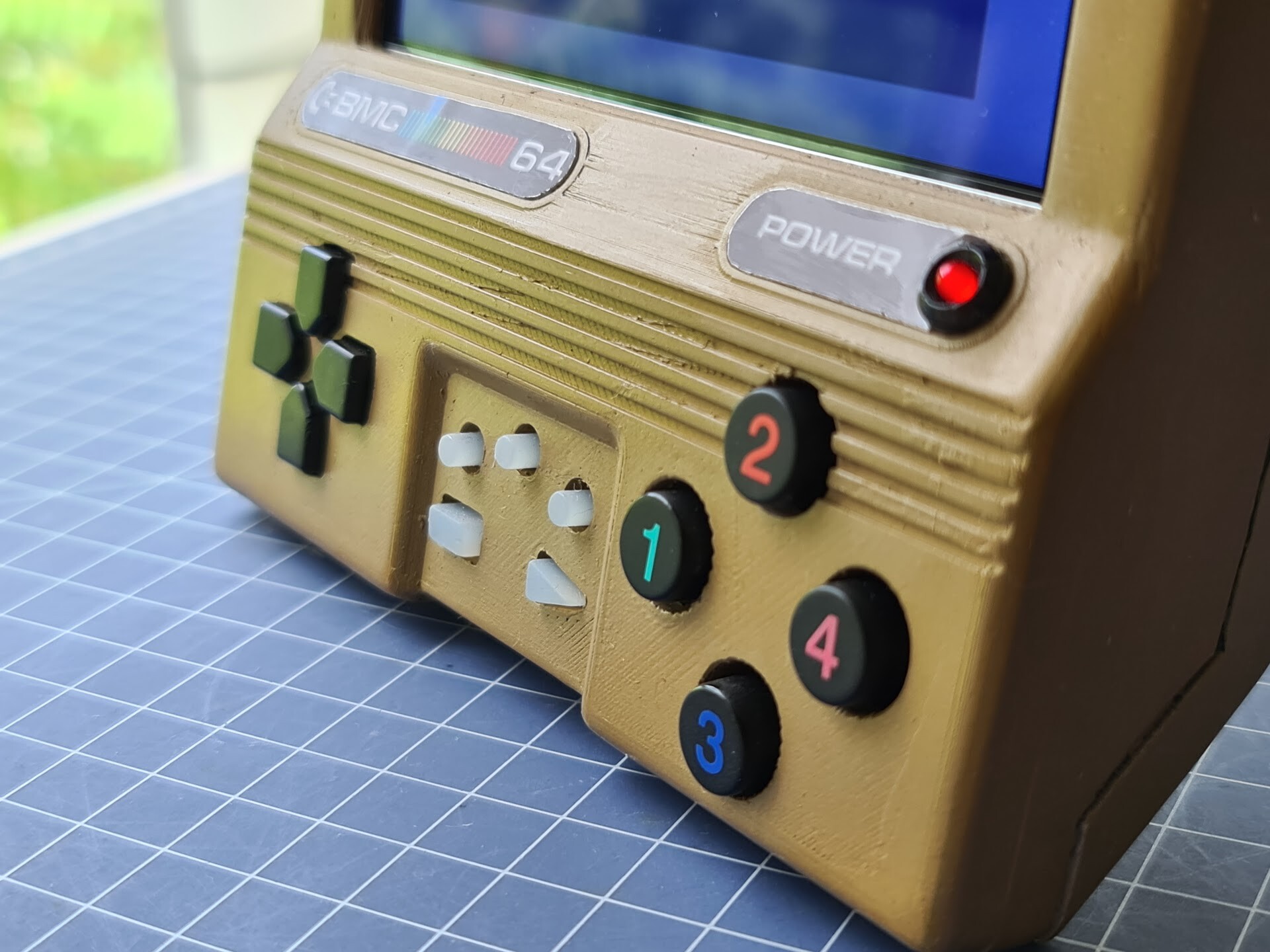
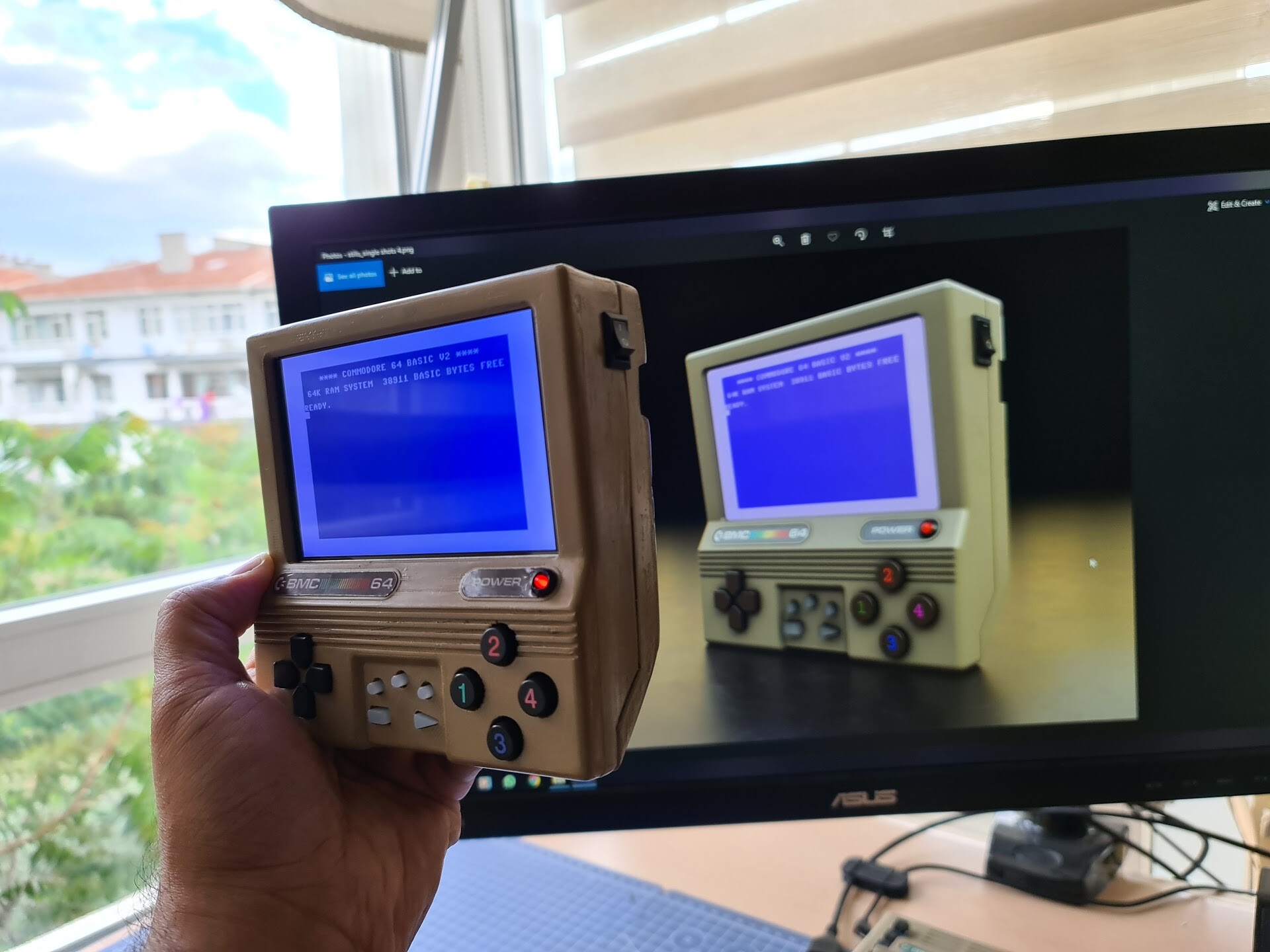
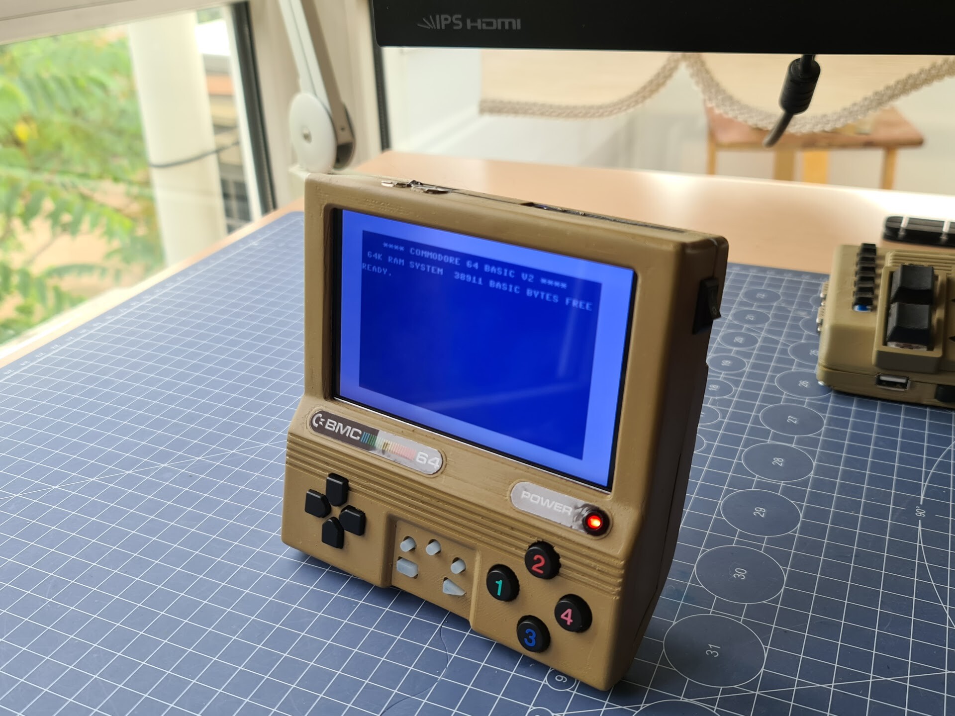
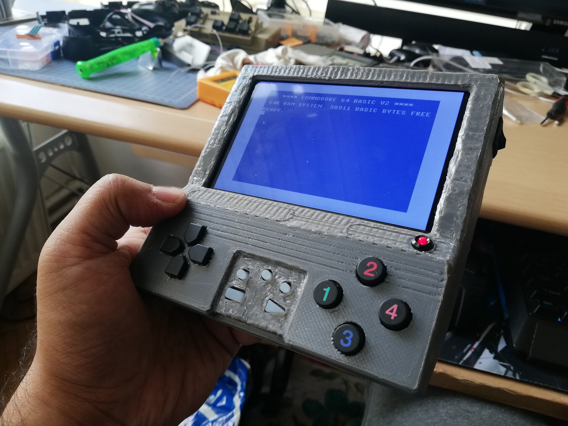
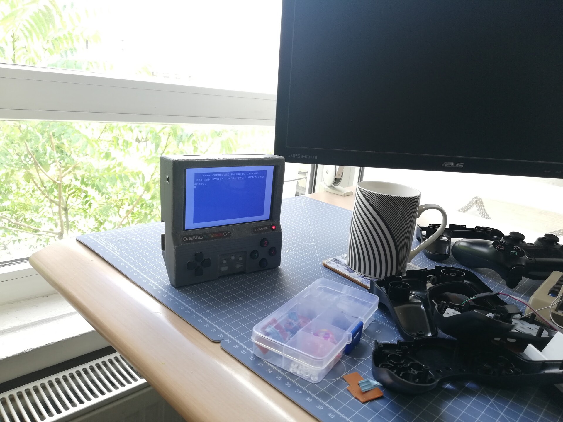
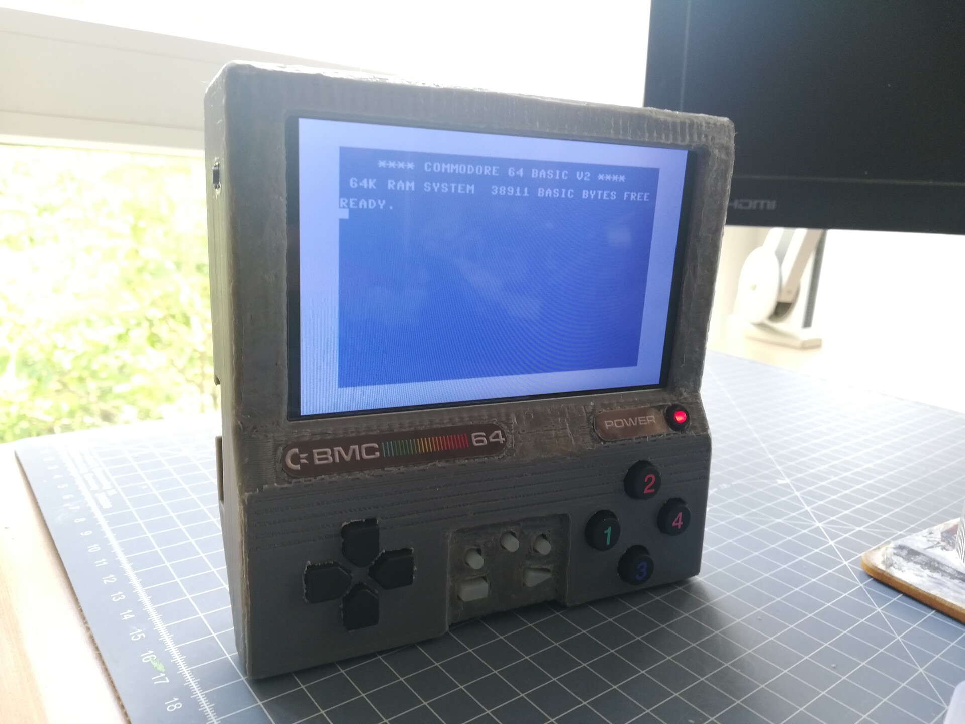
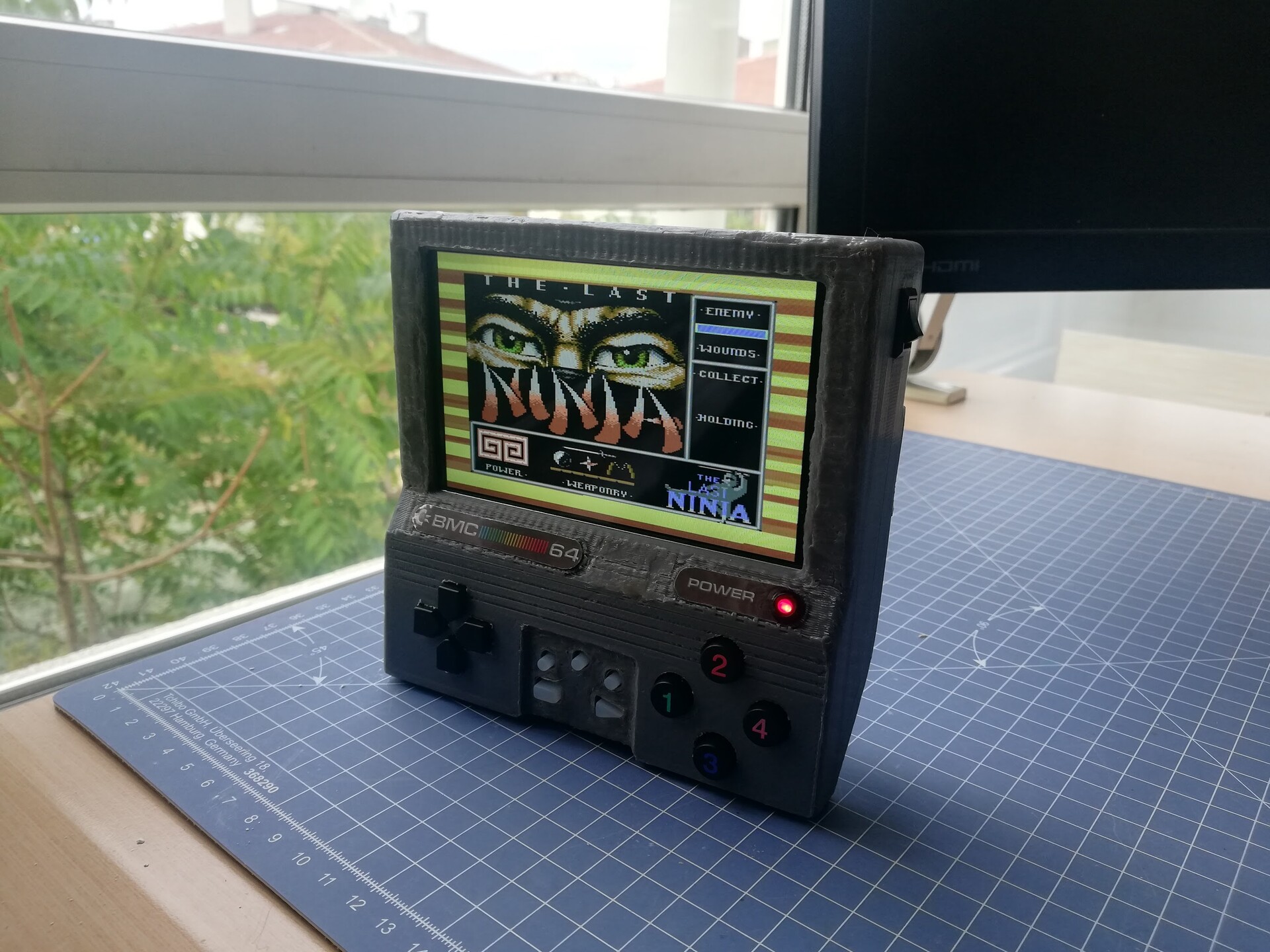
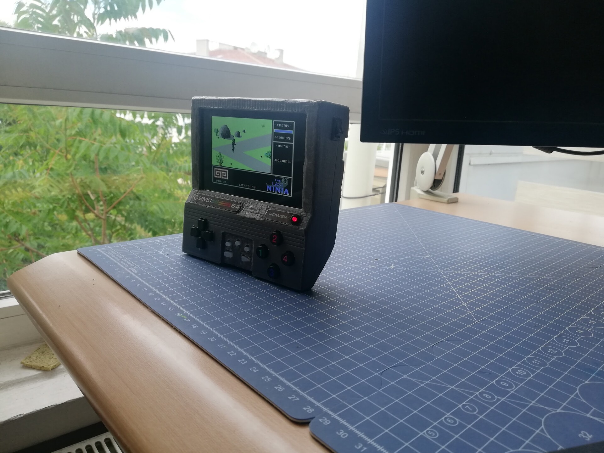
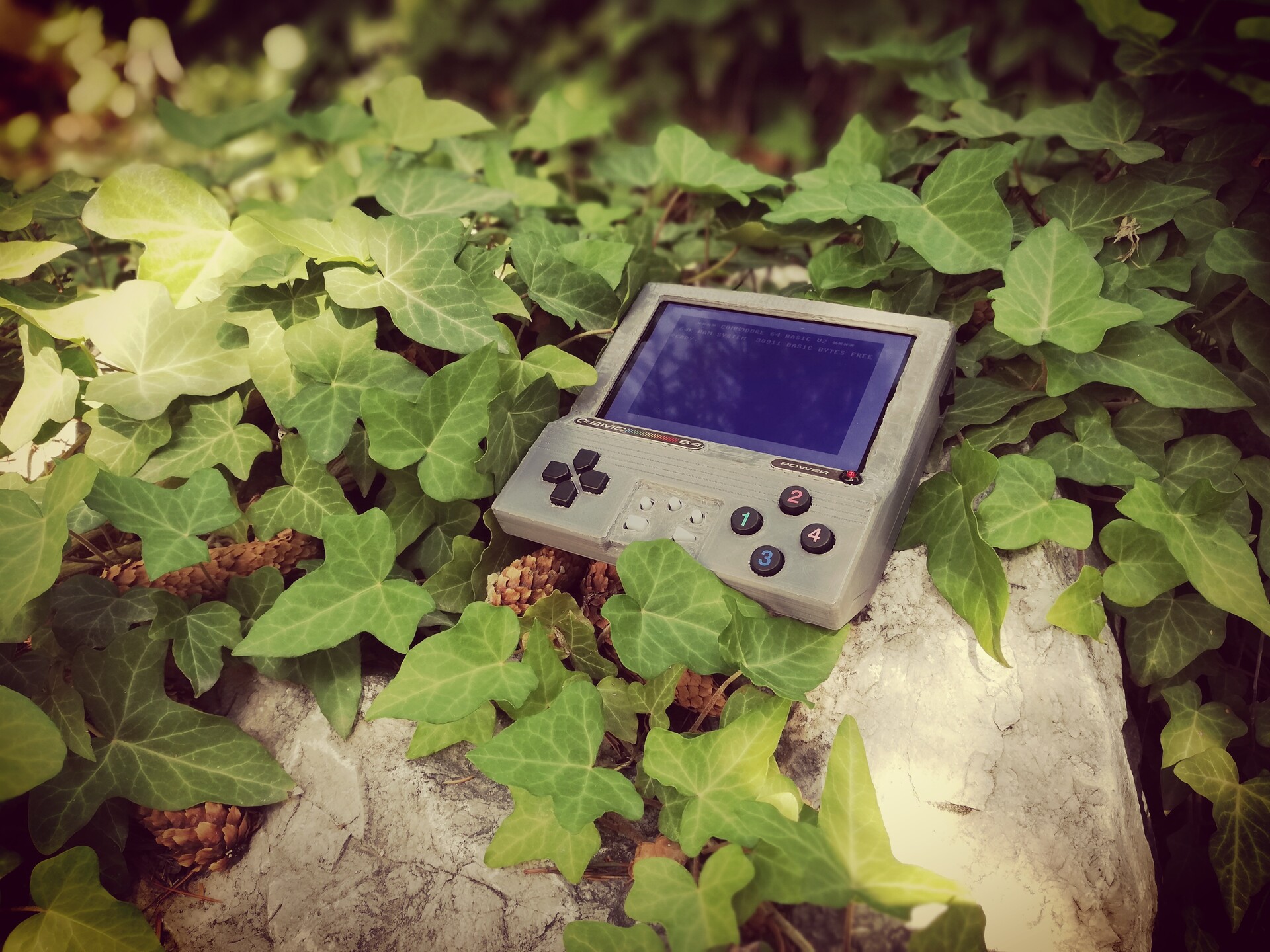
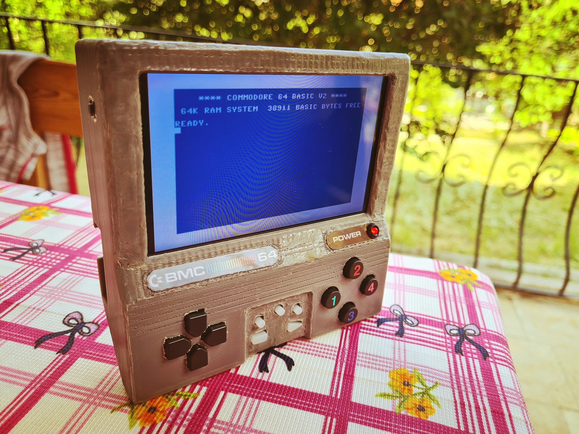
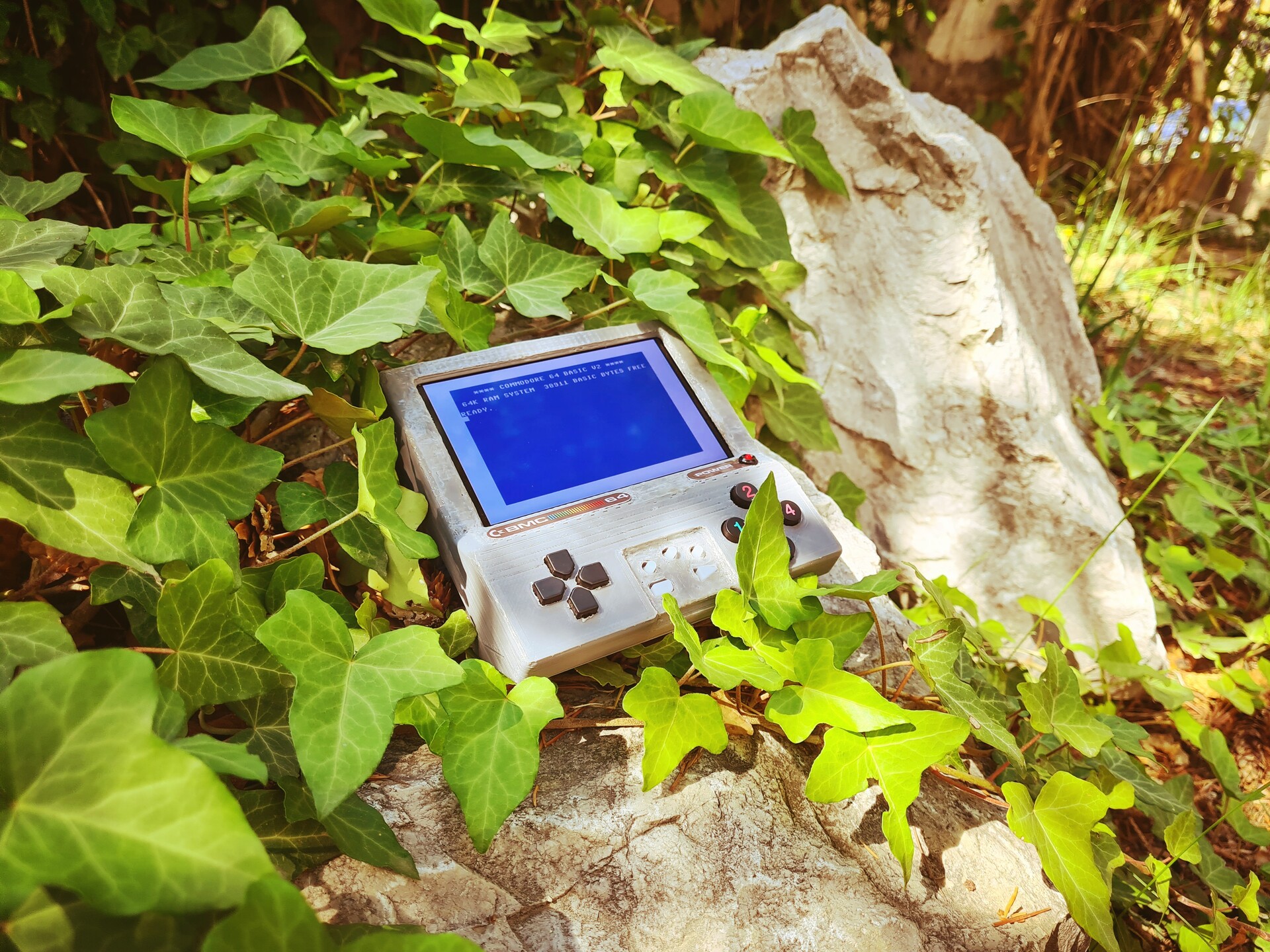
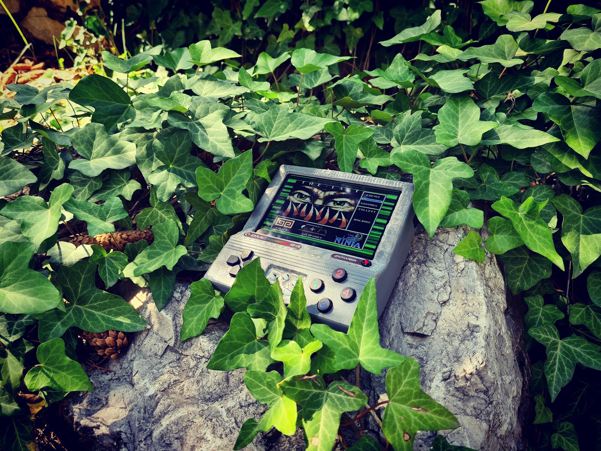
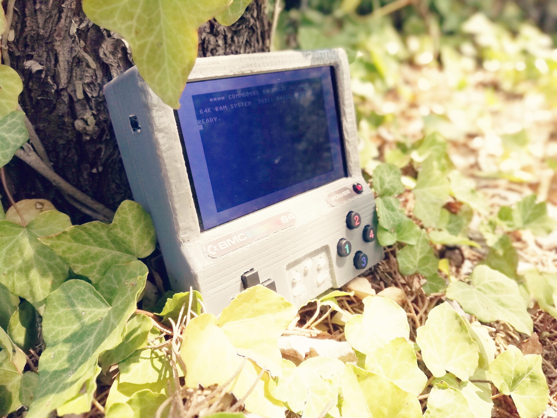
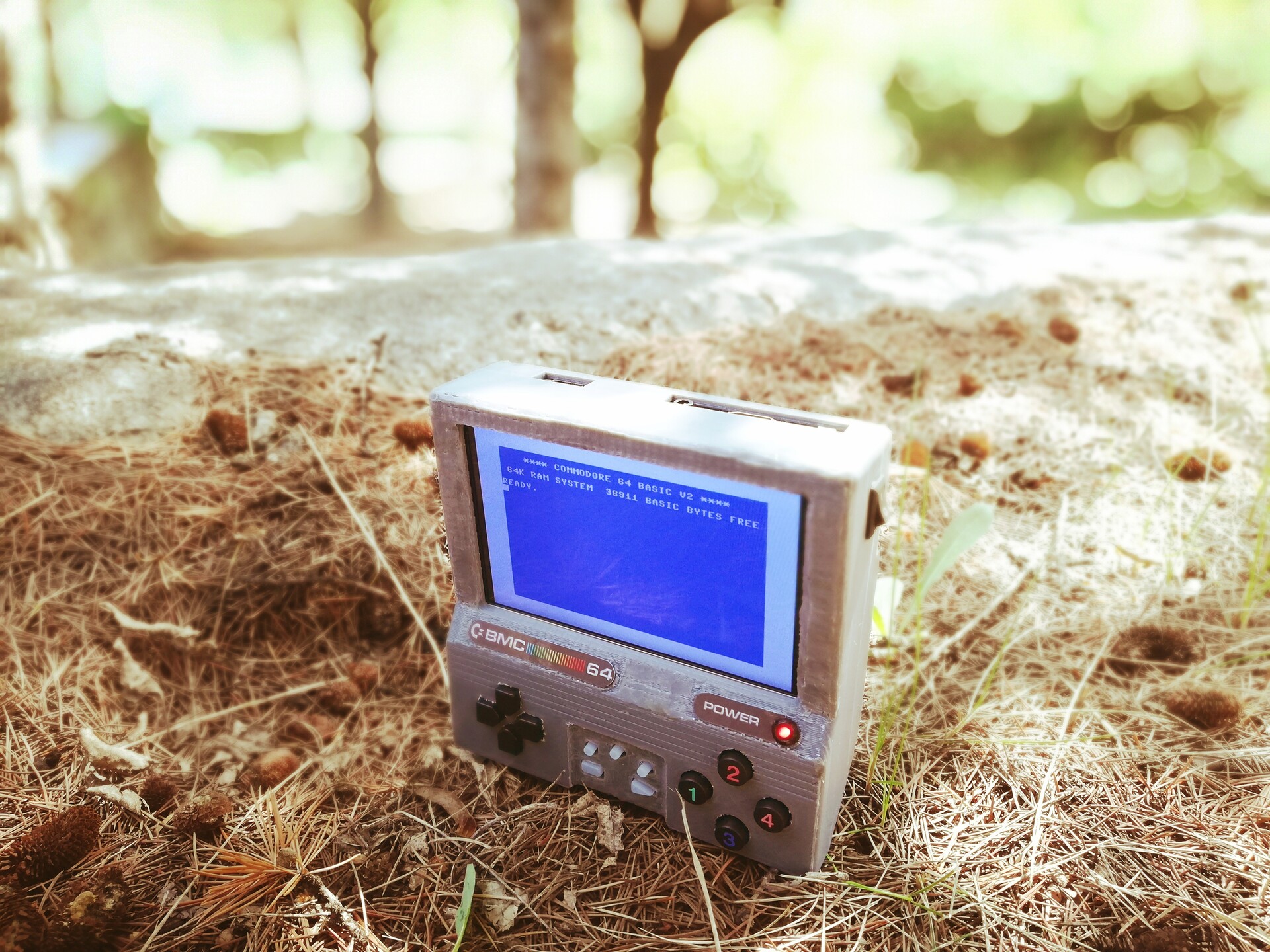
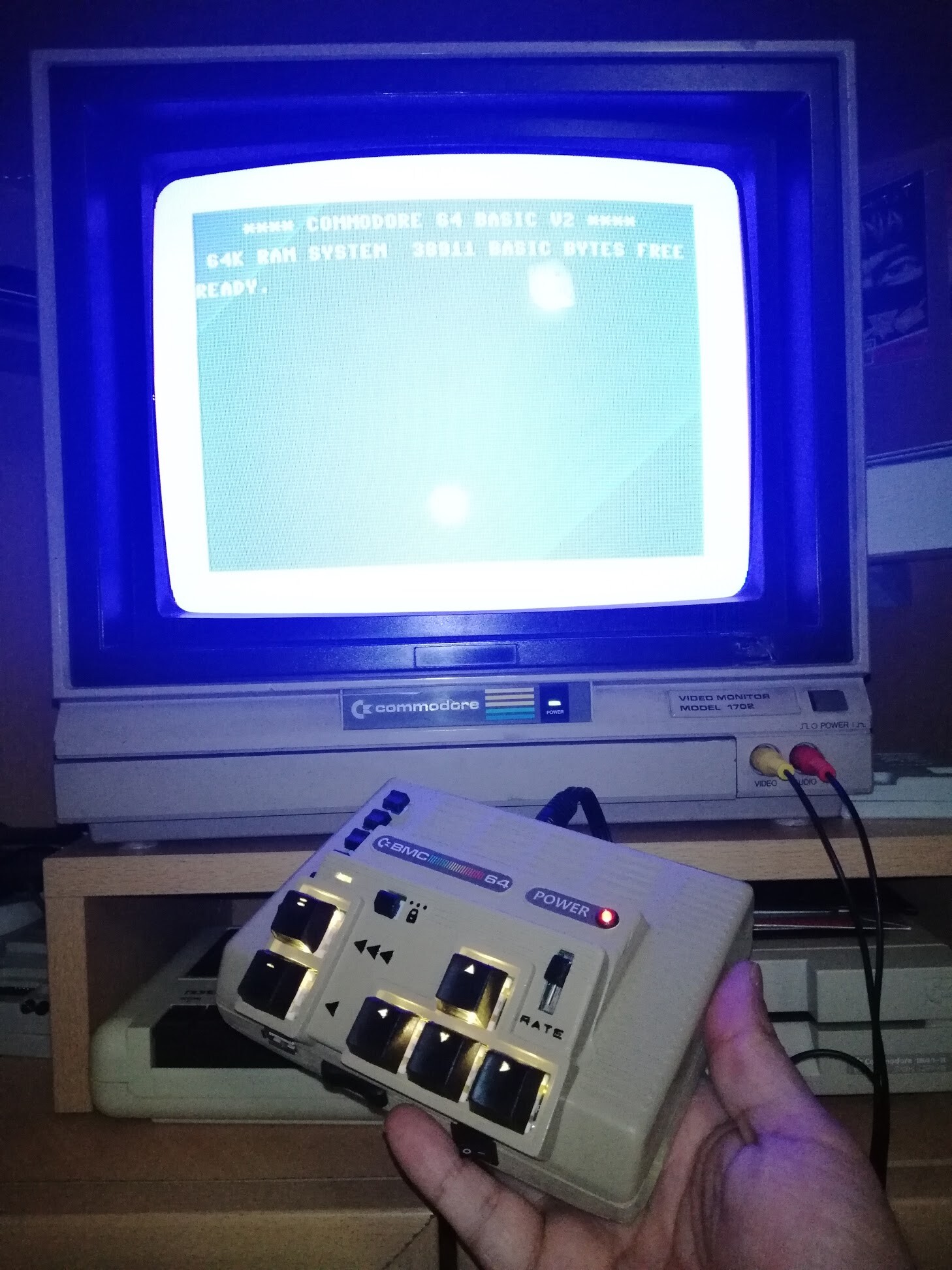
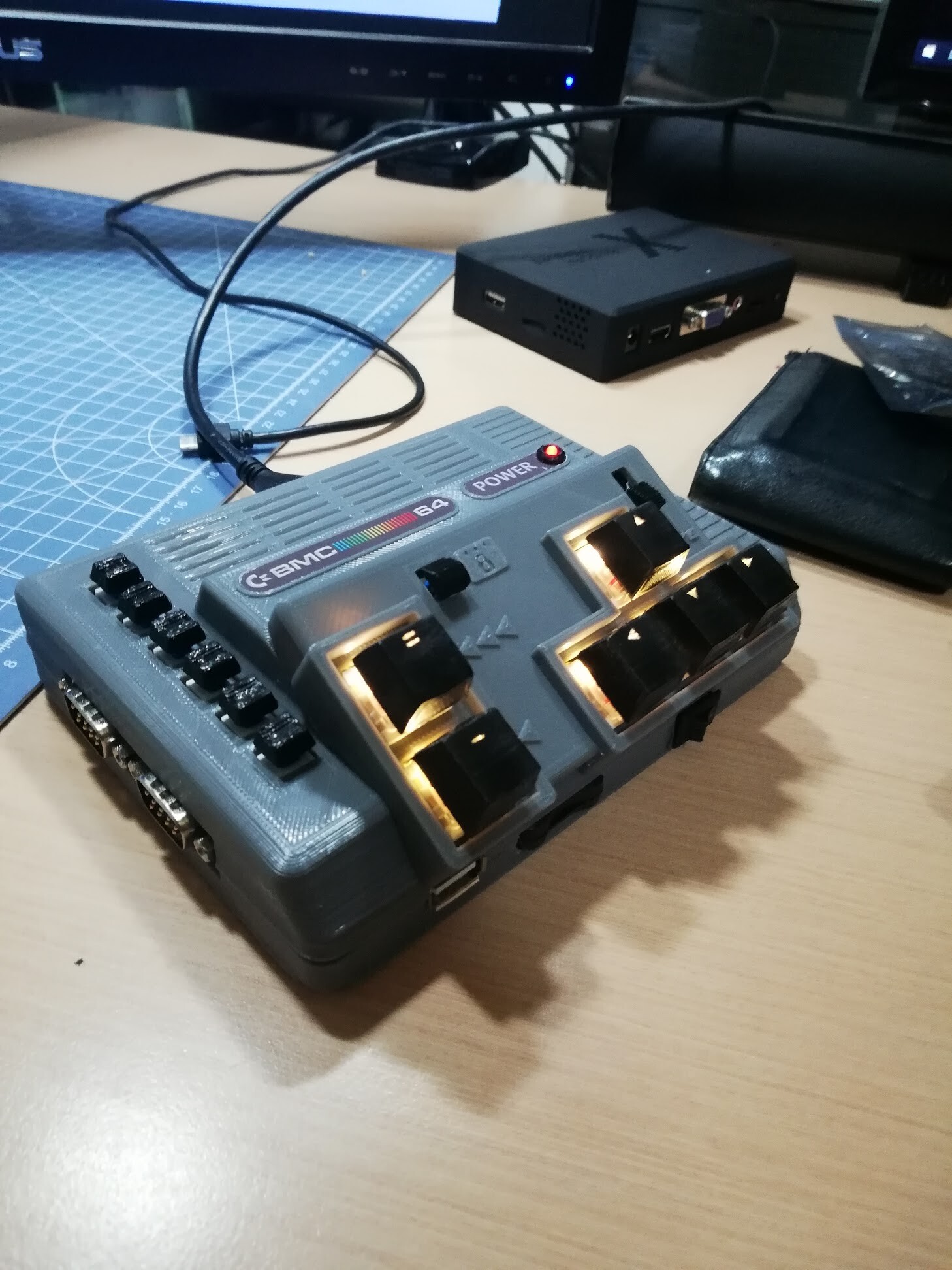
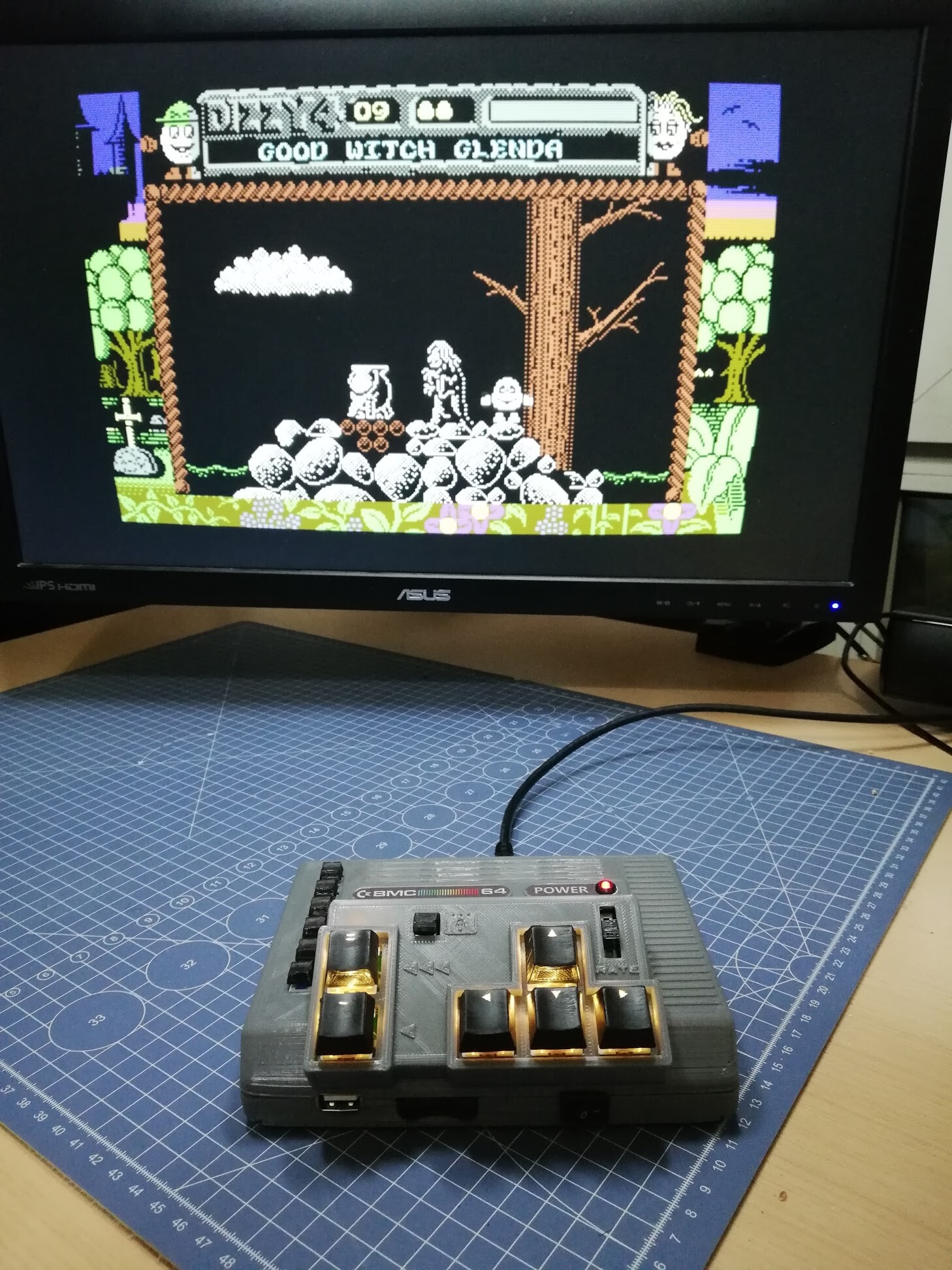
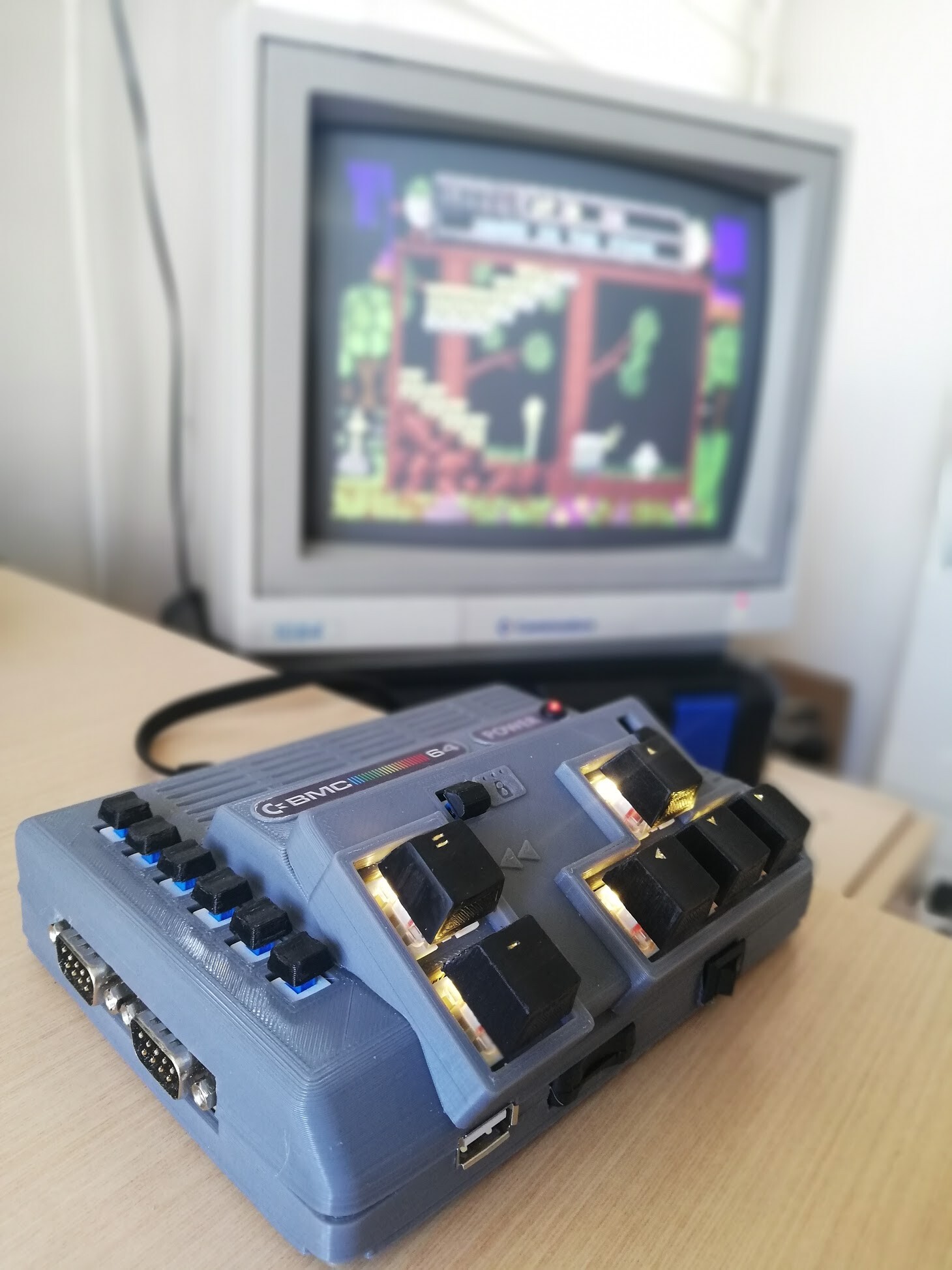
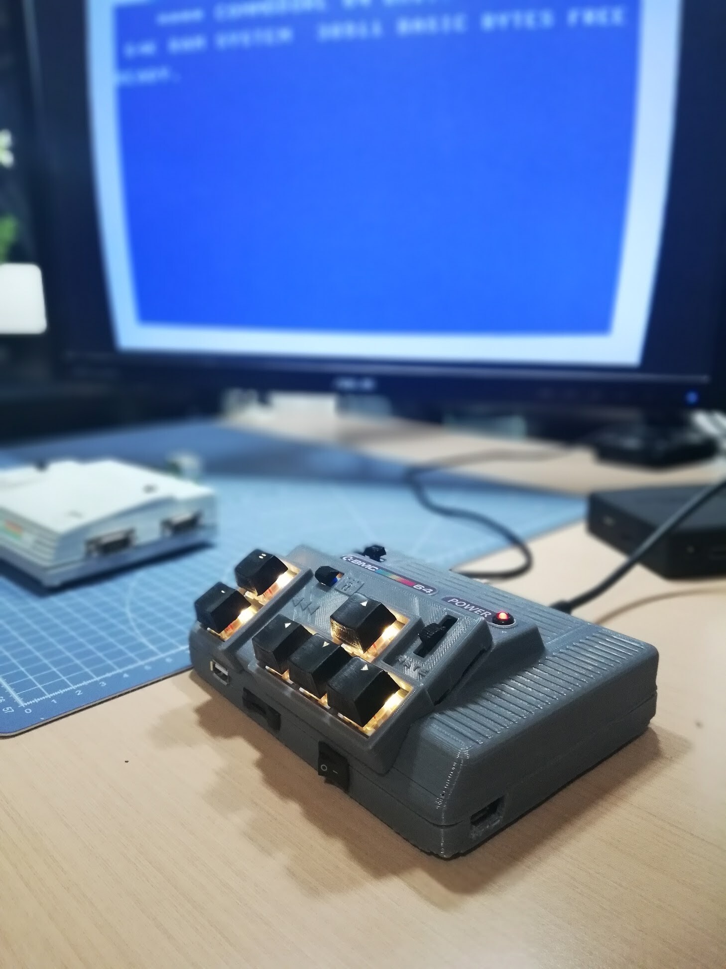
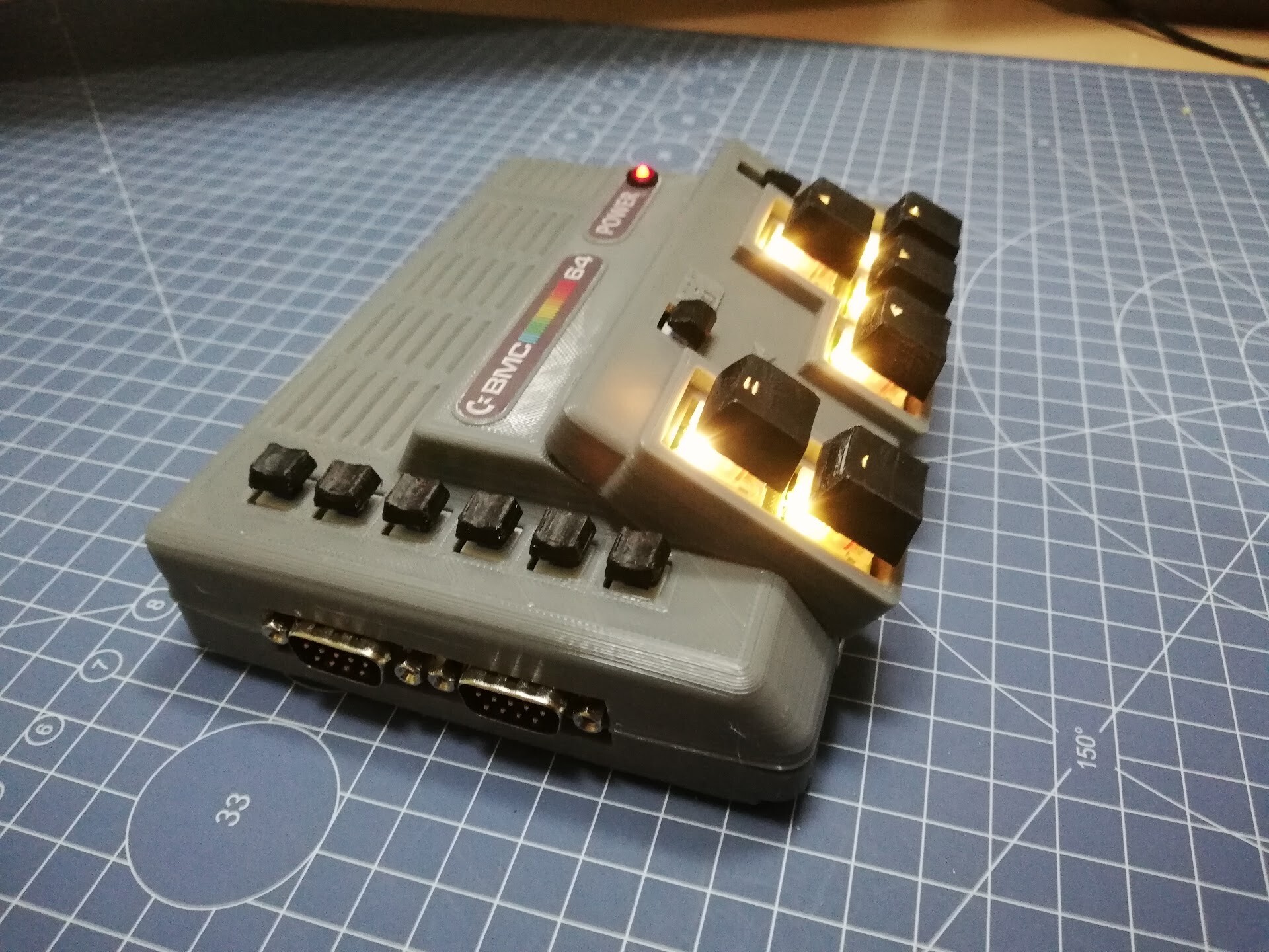
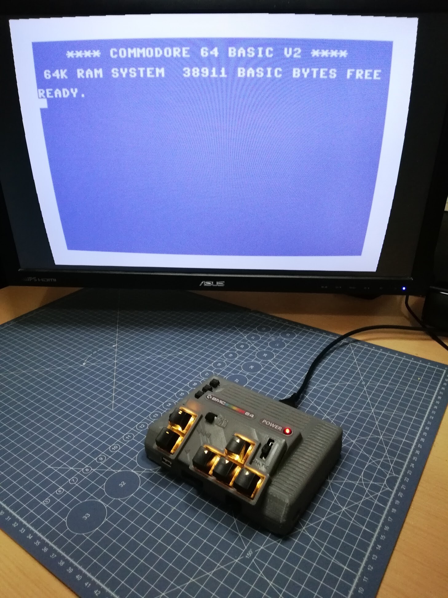
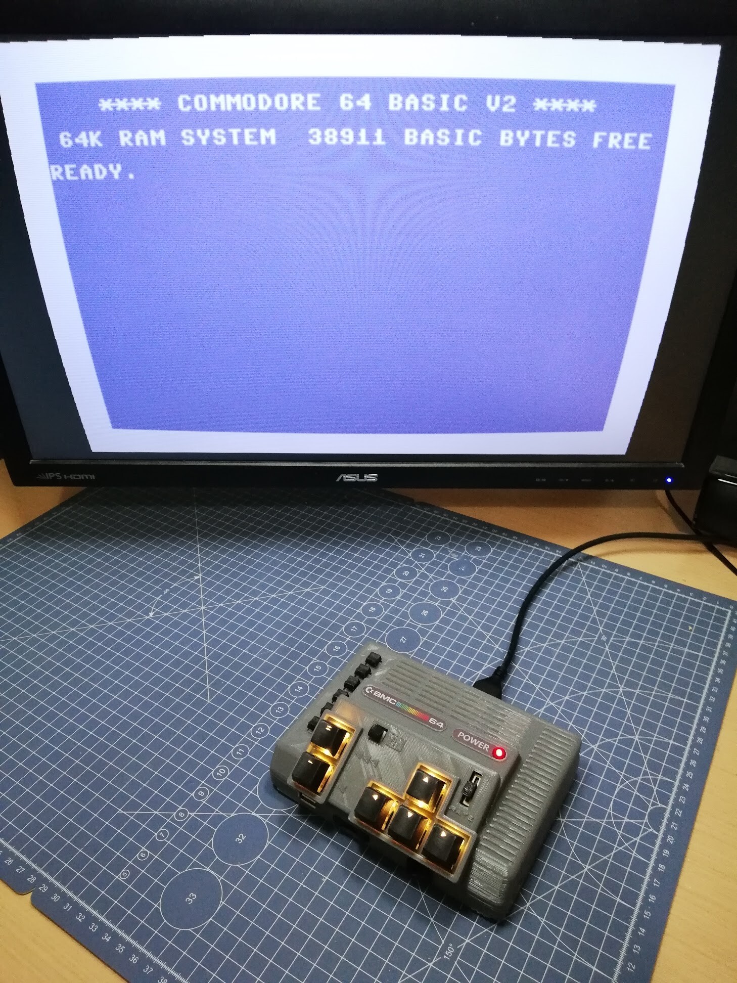
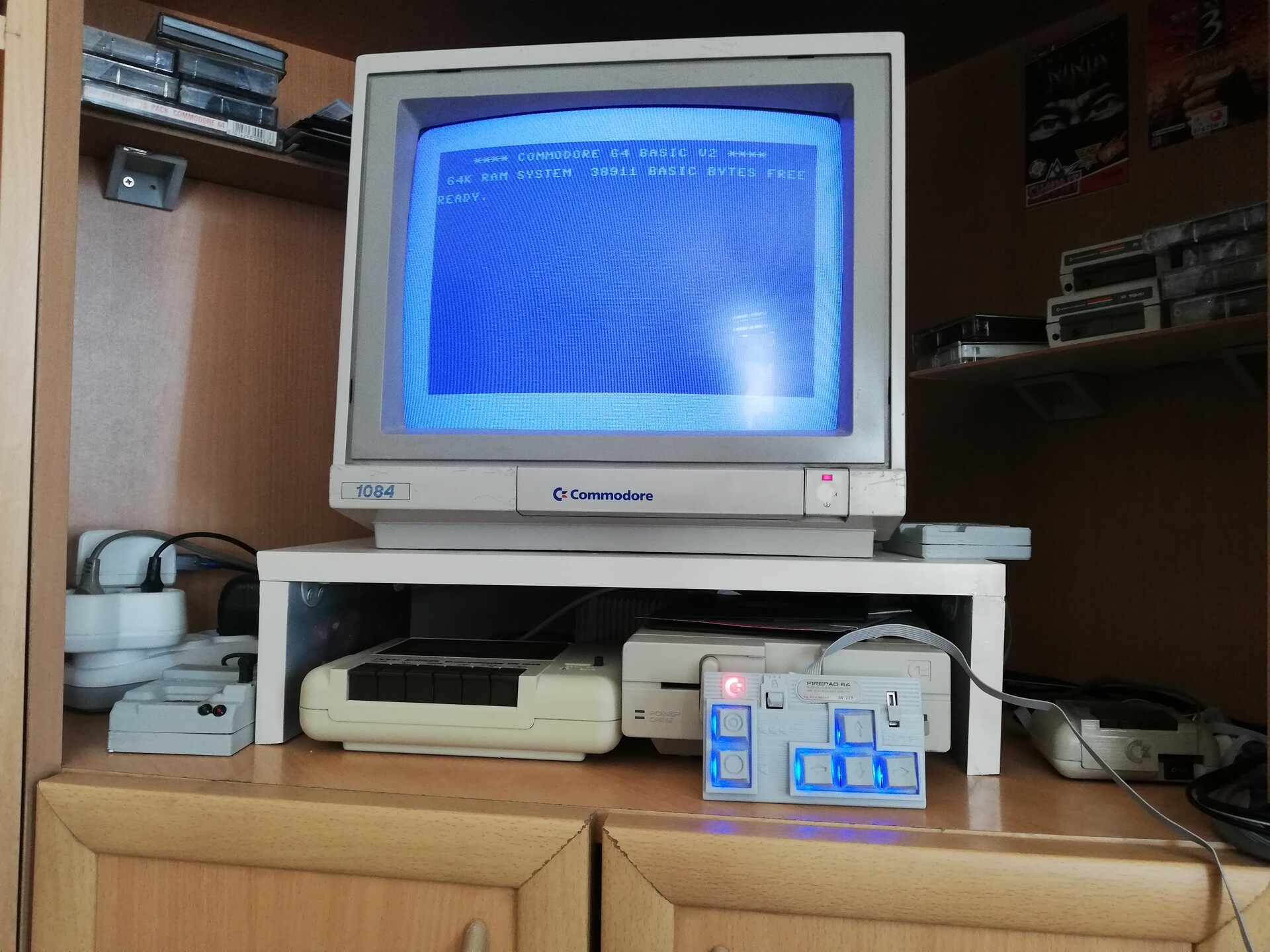
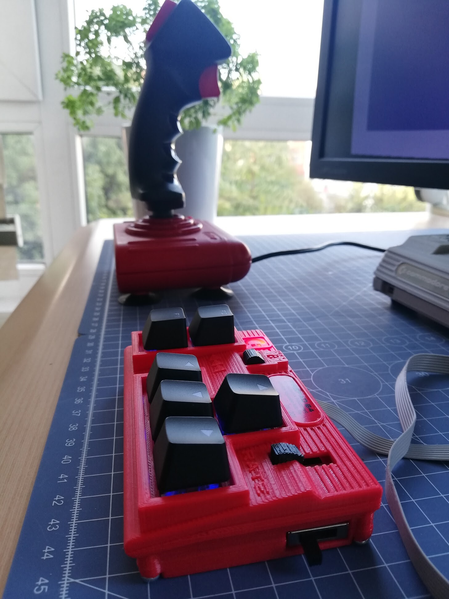
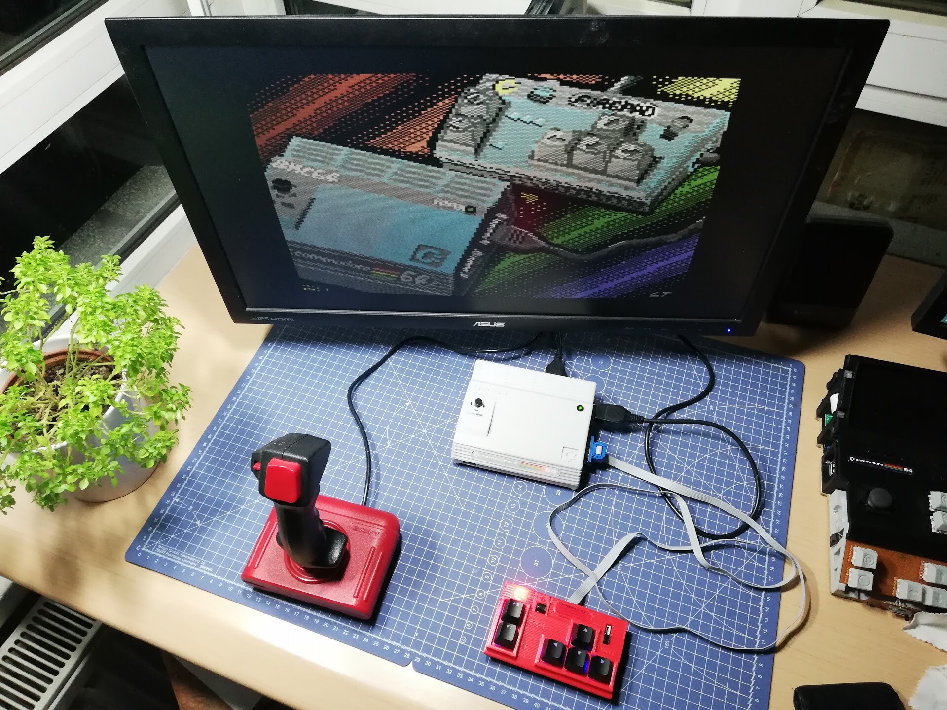
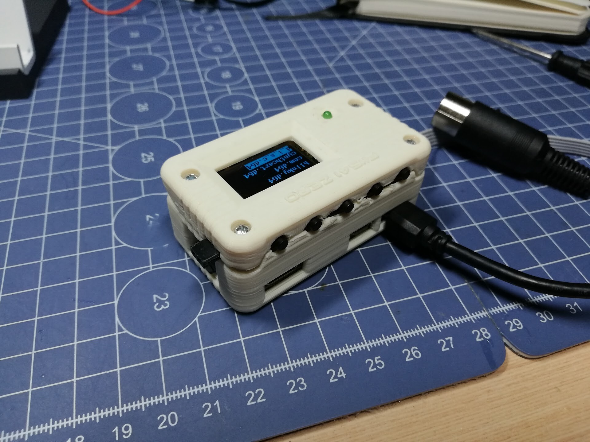
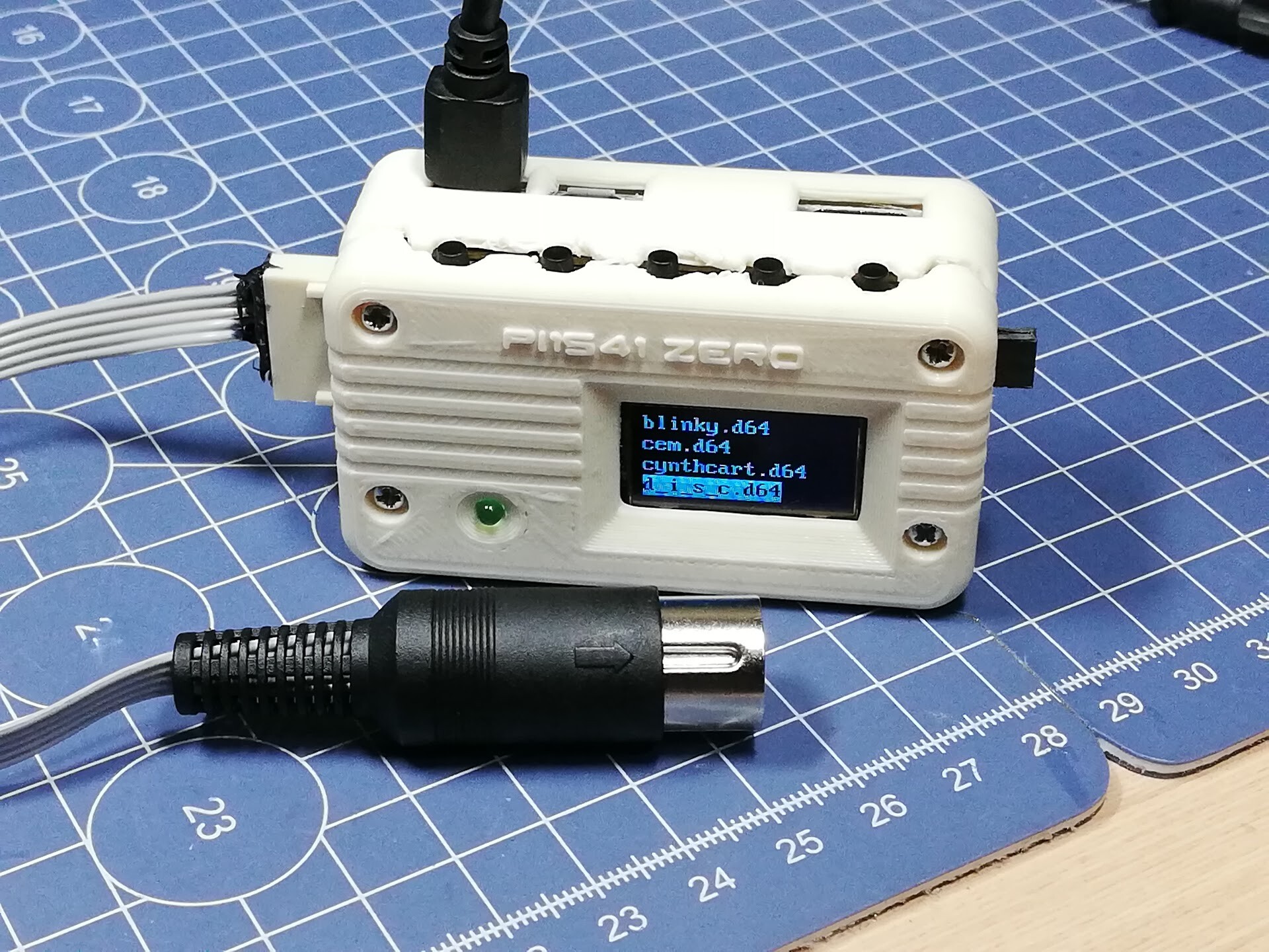
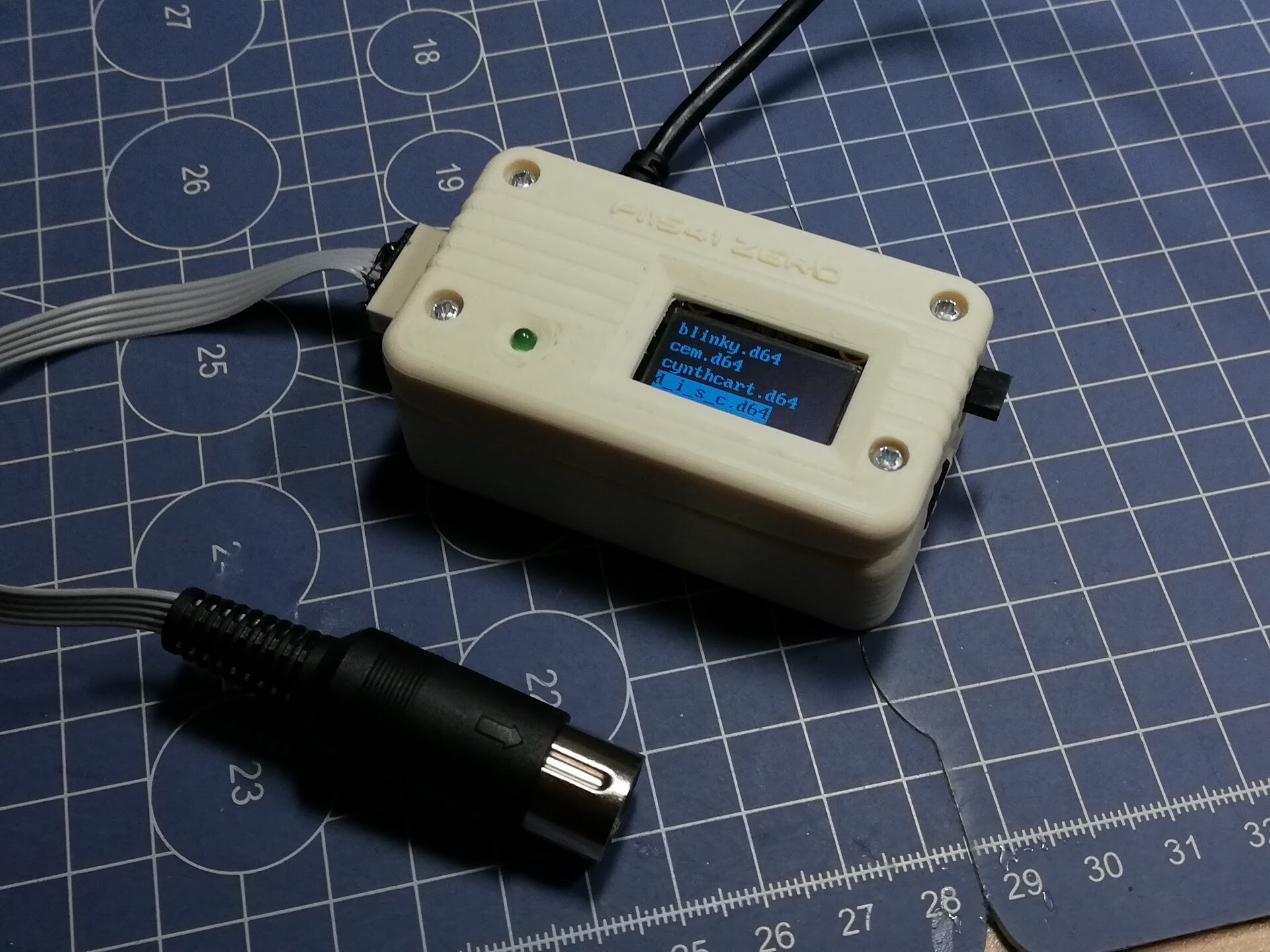
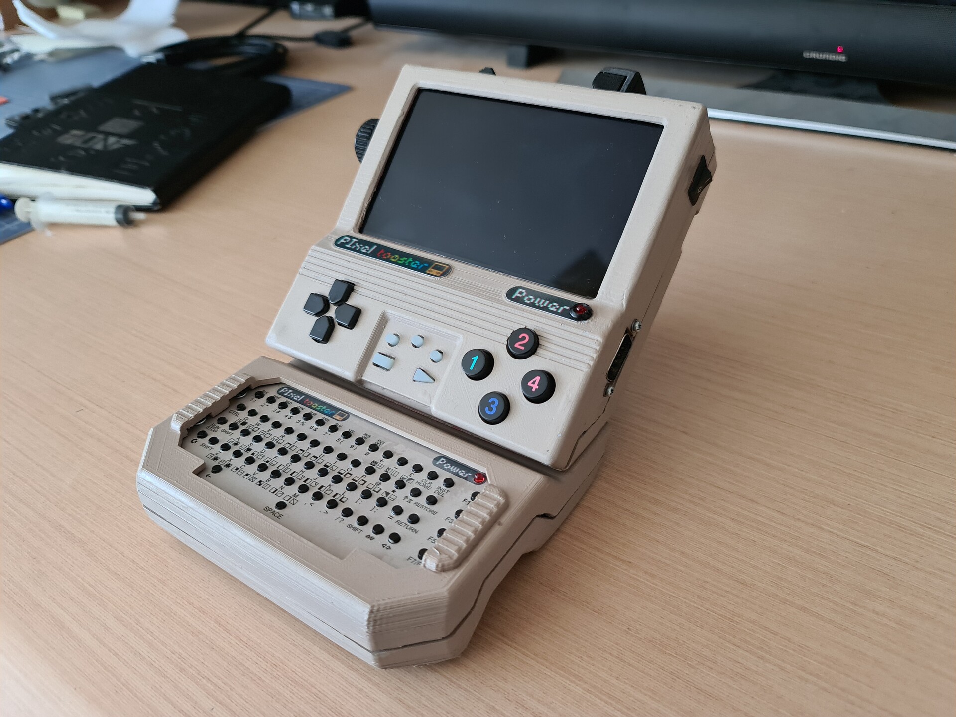
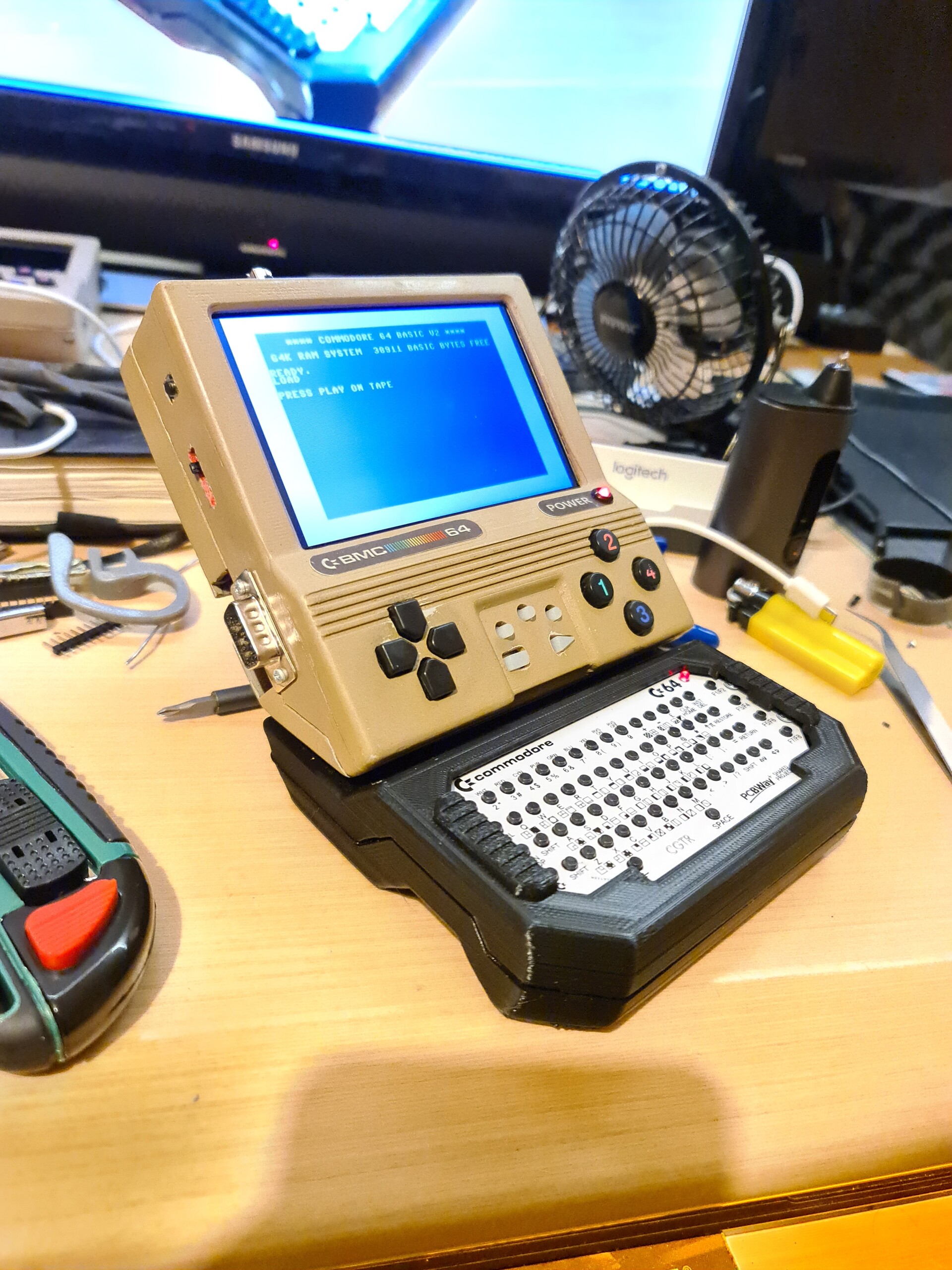
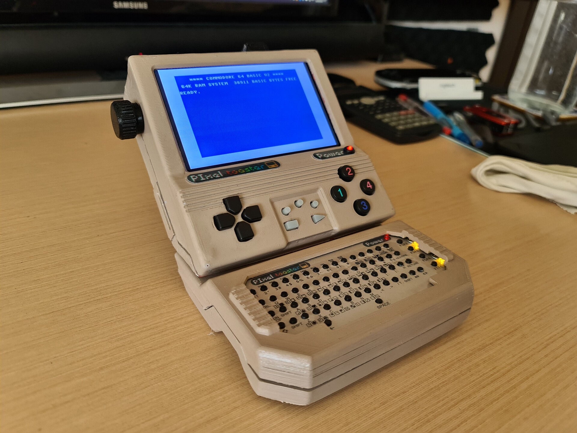
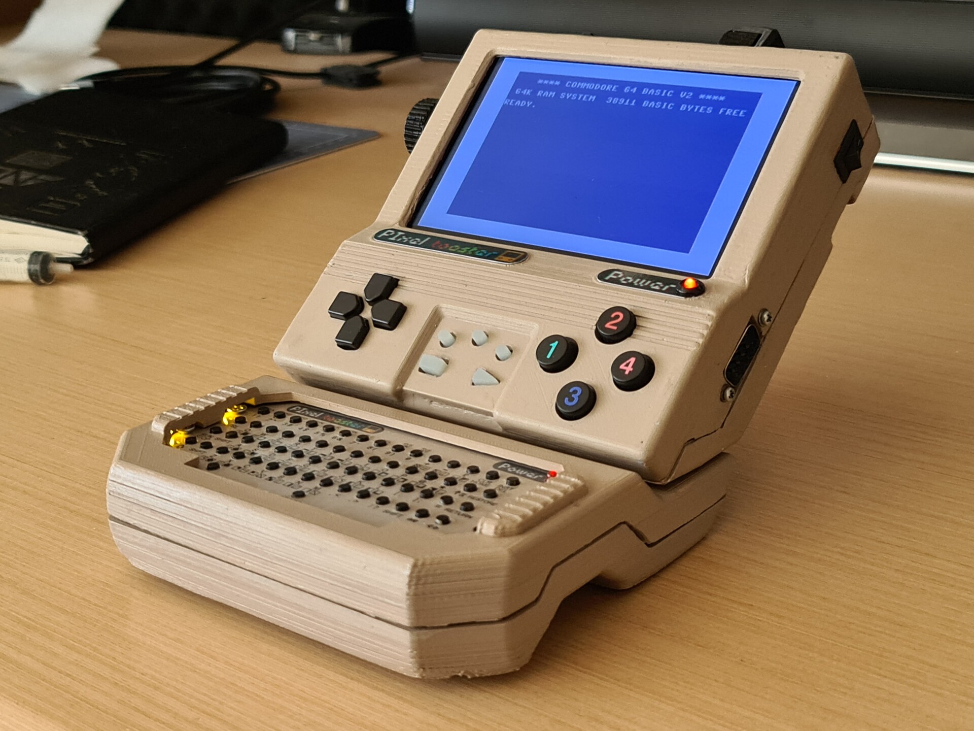
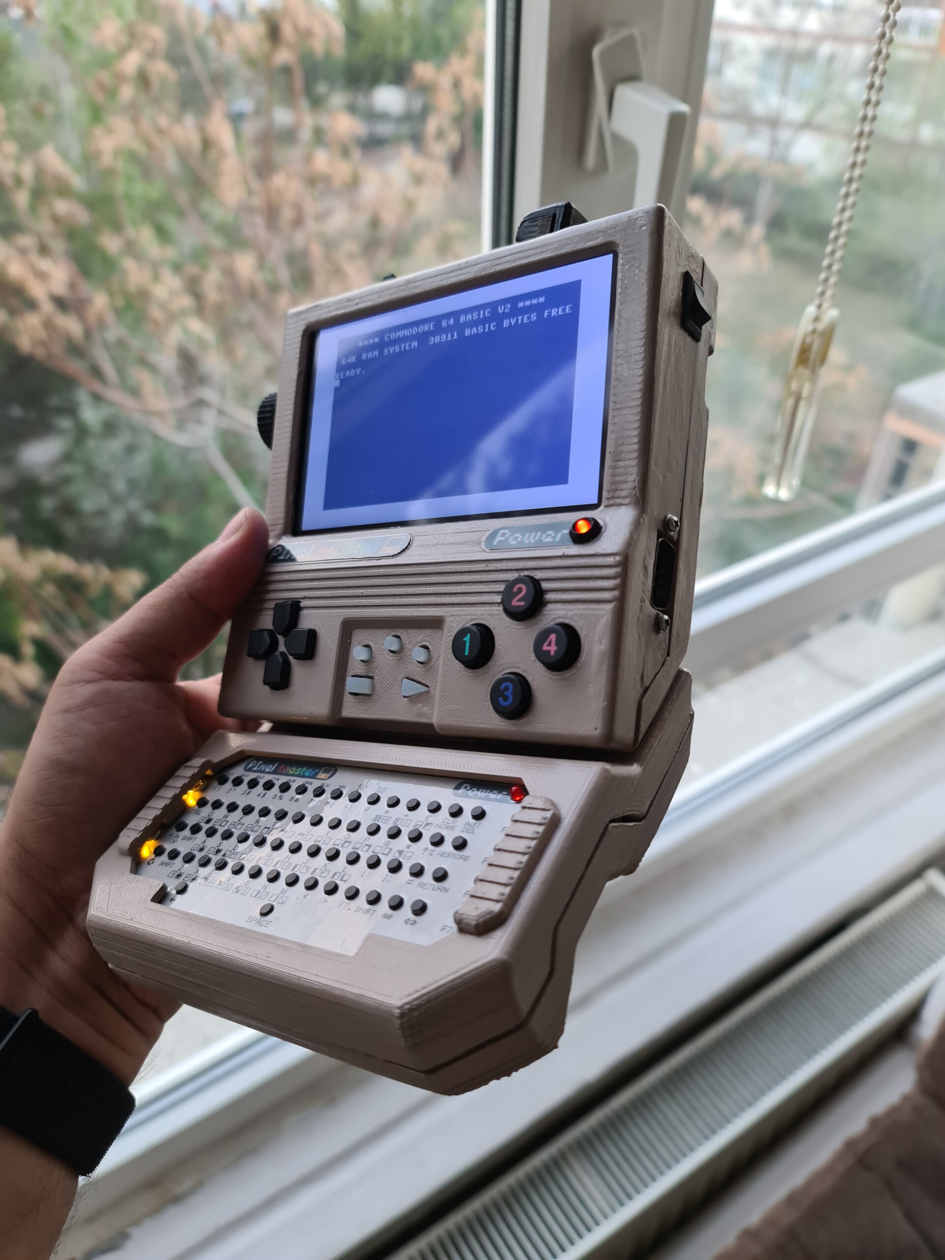
And finally completed this project. Here is the final shots about it. 

It was a real fun making this device get closer to my reverse-visionary HX-64 design (https://www.artstation.com/artwork/dOqA8K) and it was great to make up some homebrew workarounds during the process. I hope you like it too!


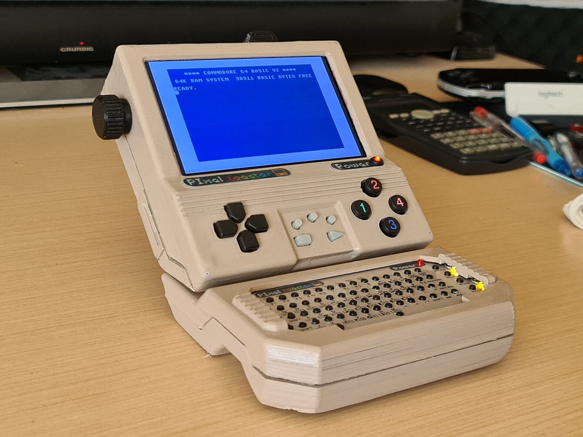
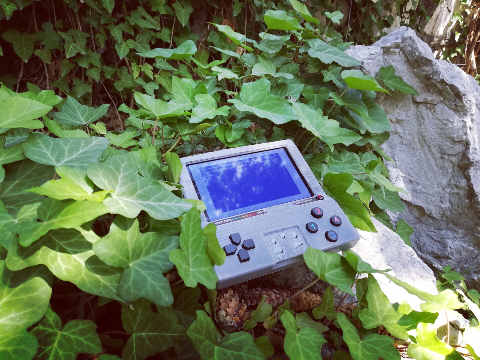
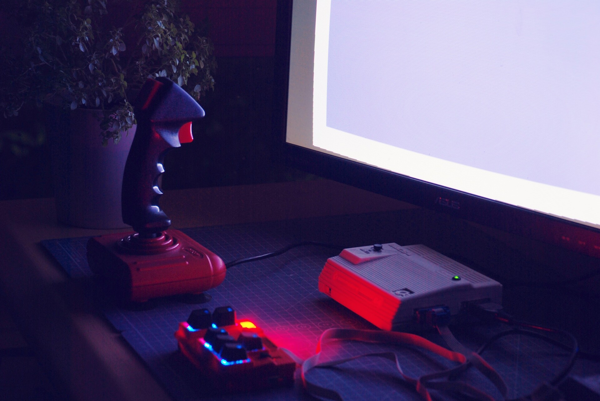
And some FPV shots :)
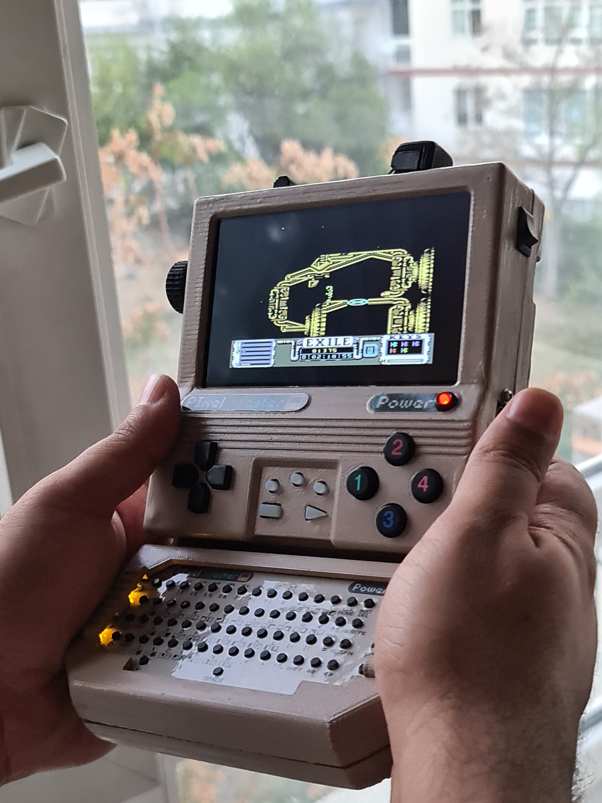
Cheers!

Handheld Commodore 64 Project - Finalization

Making Of / 24 June 2021

Hello once again,

Previously I made a case design for a handheld Commodore 64 that I made by a Raspberry Pi. You can see the making of process by this blog post.

https://www.artstation.com/blockmind/blog/lMOo/making-of-handheld-commodore-64-project

I know that project has been a disaster on 3d printing, so the resulted case was not looking good enough. 

This posts shows what I did to save the look of the device :)

As a started I re-printed the top part.

Next I used putty over the case parts.

And sanded after it dried.

I painted the parts with a primer.

...and made some tiny scratching on cavities.


Now it's time for painting with reference color!


Not close enough, but still it can be used for the first coat of painting. 


Second trial had been better on match.


And this is the resulted piece!

Acceptable color match!


And leaving some more shots here:


I hope you like it this post process. Cheers!

Making of Handheld Commodore 64 Project

Making Of / 20 June 2021

Hello, I'm here with another homebrew Commodore 64 Handheld project! It is a Raspberry Pi-emulated electronic assembly. It has it's own screen, it has two 18650 batteries inside that makes it work for 3 hours and 55 minutes in full load with gamepad activity.

You can see more info about this device in this video:


I used BMC 64 emulator on this device. You can find it by this link: www.accentual.com/bmc64


Here is the simple diagram of the components

First I combined these parts on my table and measured them. I modeled rough blocks of these in Solidworks and made a placement first.

Next by considering the port clearences and placement, I modeled a 3d printable case.

After modeling is done, I 3d printed the bottom part first and fixed the components on it.

For the controller part, I made a different approach on this one. I directly used a controller circuit which I detached from a very cheap gamepad controller (around $4). Because all GPIO pins on the Raspberrry Pi is used on IPS screen. So I needed to connect the controller with a USB interface. Instead of doing it with an Arduino, I directly used a gamepad circuit which was faster way :)


And fixed the screen to top part as well.


And we have the whole system cased!


And system works! (I know I work messy - P.S. no apricot seeds are used on this project)


The top part was 3d printed very bad because of some filament issues and placement. I tried to recover the bad surface by a 3d print surface finisher tool that makes ironing.


I know, it's not perfect but at least it can be sanded and painted later...


Tape loading!

The last ninja!

♥️

Dimensional reference photo (metric)

Some nature photos! In my childhood, some travels we do was sperating me with my Commodore 64. I wish it was possible for me to build this device in 1989 :)


And some renders! You can find the rendering project page by this link: https://www.artstation.com/artwork/GalrWW


I hope you like it! And thanks for your attention as always!

Portable BMC 64 Emulator - Mk II (Painting)

Making Of / 30 March 2021

Last weekend I painted this case by trying to match the colors of breadbin cases. 

Actually, it was very hard to match the color by mixing acyrillic paints that I have. 

Anyway, first I applied a surface primer (gray) and then used sandpapering to clean up surfaces. After that I used putty to fill layered surfaces that caused by 3d printing. And applied sandpapering again. 

Careful while using this kind of putty products (in my case Tamiya Putty). There are huge warnings about how hazardous they are.

I'm trying to match a color here but it's far from good. So I decided to use it as a one more primer layer to sandpaper once again. 

Sandpapering again has made the gray at the bottom look more visible like some Substance Painter edge damage filter is applied :)


Color in the container is my second mix where you can see that previous one (the right part) looking more off.

I'm using airbrush for the job BTW.

And looks better.


Finally I assembled the pieces and paint the icons on the front panel with black permanent pen.

A close up with flashlight.  

One comparison with Commodore 1702 monitor.

Now it looks more like the one I rendered for the the blister pack project on my portfolio :)

https://www.artstation.com/artwork/lxbNeo 


And oıne final comparison with before and after the painting process.


Portable BMC 64 Emulator - Mk II

Making Of / 18 February 2021

I'm here with another case and electronics design related to BMC64 Emulator (https://accentual.com/bmc64/). It's a Commodore 64 emulator for Raspberry Pi devices.

My purpose was to assemble a portable All-in-one device to be usable by just connecting to a TV or Monitor by a video cable.


Previously I made a similar design which is detailed by this link:
https://www.artstation.com/blockmind/blog/NgDK/portable-commodore-64-design-with-bmc-64-emulator

This time I combined this design with my Firepad64 design (Thanks to my brother Cihangir for this advice). BTW, Firepad 64 is a fire rate adjustable controller for 8 Bit computers. For more detail:
https://www.artstation.com/blockmind/blog/RYL0/firepad-64-v3-home-production-logs

First you can check this introduction video I recorded about this device:

Now let's see how I made it:

First I gathered the components and soldered them. 

Power Bank Charge Unit

18650 Battery

Raspberry Pi 3A+

2 x DSUB9 Connectors

6 x 8mm Switches

SD Card Expander

Firepad 64 mechanism (Custom made)

USB Expander (Custom made)

GPIO hat (Custom made)

3mm LED light

---

I made a GPIO hat for the Raspberry to distribute all joystick and custom function pins to buttons.

Once I gathered all the components together, I designed the case by part by part which I'm lucky that all fit together at the end.


First I designed the bottom part and 3d printed it. Made the assembly fixed onto it by screws.


Next my measuring the result with the bottom part, I designed the top part of the case and 3d printed it.

Connected the firepad unit to it by screws & nuts.


All system is ready to be encapsulated.

I made this translucent keycaps by 3d printing. I applied translucent filament into the direction icons and used sandpaper to smooth and blend them together.

Here is the lit version with labels I printed with my color printer.


Finally I printed little key caps fot the left panel, and device is ready to use.


It's connected to HDMI screen.

And here it's connected to A CRT screen (Commodore 1084).

Looks like batmobile right :)

And more photos... Thanks for your time!


Replacing Commodore 64 Key Mechanism by 3d Printing

Making Of / 20 December 2020

Yesterday I was detaching keycaps of my Commodore 64 to clean the mess under, because some of the keys were not pressing well. But while detaching the keycaps I broke 19 of them. Since the time passed, these key mechanism plastics got crunchy.

Normally this means you need to send your computer to service, and make them replace the key mechanism. Since there is no service of this brand, that mean I need to solve this myself.

First I tried to super glue the thing but it was not a good idea, since doens't work. After that, I decided to 3d print the parts that I broke down.

But first, I needed to remove the broken part inside the caps. For that, I used "wine cork technique" with a tiny screw! First I screwed it 3-4 steps into the broken part and I pulled it back.

Next, I modeled the existing part with Solidwoks by taking measures with calipers.

Before printing this kind objects that needs to be used on mechanical purposes, I make the slicing angular (about 30°). This way printing layers will be angular, so part will be more durable for the forces on the arms.

Since it is roughly 10mm to 18mm part, I wasn't sure that it will come out correctly. Because there is a rubber conductor part that needs to be attached to that part to make it work.  

I'm very happy with the result.

Time to attach the rubber conductor.

Let's apply the replacements!


Alignment is perfect as well!


Works great! Thanks for reading.

Also this part can be downloaded by this link: https://www.thingiverse.com/thing:4691398

Firepad 64 - V3 - Home Production Logs

Making Of / 08 December 2020

Hello, 

Recently I made an advancement on my Firepad64 design, which is the Version 3 (possibly the last update) for this device. It's a joystick replacement for Commodore 64 that has a keyboard layout for easy playing. You can check this post to see the first creation steps of this device:

https://www.artstation.com/blockmind/blog/zPLm/making-of-firepad64-joystick-replacement-for-commodore-64

I want to share the steps of the creation of this device because (except the PCBs) it's all homemade manufacturing which is a great achievement of our world has come to. I didn't even get out from home to create this "mechanic and electronic" product. So I find this important to share the details of creating an end-user product at home. It's cyberpunk! :)

Anyway, Version 3 of Firepad64 has 3 major advancements after the previous version.

  1. Professional Outemu brand mehchanical keys with regular linear (red) and clicky type (blue) versions.
  2. Backlit Lighting
  3. Screw Assembly instead of shrink-fit


This video shows some details of the product but it's in Turkish.


The most problematic part of this update was to adapt the Mechanical buttons to my existing PCBs. Because the pin positions are totally different. Since I have some 50 pieces of the previous PCBs, I decided made an adapter for the buttons to comply with my existing boards.


Without those adapters I was adapting the keys with prototyping boards. It was good for some 1-2 adaptations but it was not durable and it was so much time consuming to make the buttons adapt to my existing PCBs.


Wtih the help of the adapters it was easy for me to make usable mechanical switches in a fast way.


Next I 3d printed a template to make the perfect alignment for the keys before soldering them.

You can see the lighting under the keys. Best part of these mechanical keys, they are designed for to let the light under them. So I used a serial light cable which are used on new year lighting applications on homes to make the keys lit.

I assembled the PCBs.


This is how they shine like a Christmas tree :)

My next step was to finalize the 3d design and make the 3d printing. I made the whole design with Solidworks but I love how Rhinoceros show the CAD models. Look at this fast AO computation in viewport!

So I started 3d printing and assembled each set after they're complete.


Nice part about these keys is you can use regular keycaps.


So here is the army of Firepads :)


And finally the connector & cable design.


Time for boxing.


Enjoying Mr. Steven Wilson's great music while working on the stickers and product sheets.

...and voila!

I hope you like the steps of this home production phase for some friends from the community of retro gaming. Thanks & see you!

Easyflash3 Cartridge Case Design

Making Of / 01 November 2020
Hello! I made a 3d printable case design for my easyflash3. 


Easyflash3 is re-programmable Commodore 64 cartridge that supports all CRT files and fastload cartridge binaries like Action Replay, Final Cartridge Etc. You can find more details about it by this link: https://skoe.de/easyflash/

I used Solidworks to measure and model the existing electronic part first. I use calipers to measure all distances and clearences while creating the model. And next I modeled the case by referencening the electronic part.

This way I had a chance to get rid of that center screw which I don't like on cartridges. It's economic and easy way for an assembly but my version is more rock solid at the end with no loose fixation between case and the PCB.


You can download the models from thingiverse. I also added some label designs as PDF file. 


You can see the timelapse video by here:

Here are some photos of the assemblying 3d printed parts. Hope you like it, see you on next project :)


Firepad64 V3 - Cherry Buttons!

Making Of / 19 October 2020

I updated my Firepad64, a controller device which is used as joystick replacement for Commodore 64 and other compatible devices.


Firepad 64 has an adjustable autofire system and Arrow Key (or WASD) layout for easy to play classic games with classic devices.

Let's have a commercial break :)


Firepad 64 version 1 had the more rough buttons and turn type autofire adjustment handle. 

You can check all the details about Version 1 by this post:

https://www.artstation.com/blockmind/blog/zPLm/making-of-firepad64-joystick-replacement-for-commodore-64

Firepad V2 was the same case design with linear adjusment handle and old-school click-type mitsui keyboard switches. I desoldered these switches from some mechanical keyboards that one of my friends Lutfi Öner gave me as a gift.


You can check some details about Version 2 by this link (blog post is Turkish).

https://www.artstation.com/blockmind/blog/2KYQ/firepad-64-v2

And finally for best gameplay experience, I upgraded switch type with cherry buttons. For that buttons to be usable with my existing PCBs, I made an adapter board by using cheap prototyping boards. Because conductive legs of the cherry switches are not comply with my PCBs.


This is the single adapted switch for my firepad PCB.

Making these adapters and soldering the legs one by one is an overwhelming process, so I designed a PCB layout for that job. I didn't yet ordered the PCBs, so I'm not sure if they'll fit good. Until then, I will continue to make handmade adapters.

Hand made adapters work well too.


I even designed 3d printed custom keycaps!

Voila!

After this progress, I wired some LEDs for keys. Because I can even use translucent keycaps with these lights now.


After this touches, I finally made some Red & Black concept with keycaps to make a resemblance with most of the joysticks of the era. Red tone of my 3d printing filament didn't match perfectly but it looks all right.


And photo time with my portable BMC and Quickjoy Turbo joystick!

Portable BMC64 - https://www.artstation.com/blockmind/blog/NgDK/portable-commodore-64-design-with-bmc-64-emulator

Quickjoy Turbo Joystick - https://www.artstation.com/artwork/BrJz8


Case Design for Pi1541 Zero Compact

Making Of / 24 July 2020

I made another case design ( actually I modified the last one) to comply with the single Pi1541 compact which works with Raspberry Pi Zero.

The case I modified from was this: https://www.artstation.com/blockmind/blog/AnMX/case-design-for-pi1541-zero-epyx-fastload-combo-cartridge 

3d Printable Case design can be downlaoded by here: https://www.thingiverse.com/thing:4550955 

The PCB of the electronic part is not designed by me. You can purchase it by here:

https://www.pcbway.com/project/shareproject/RASPBERRY_Pi1541_ZERO_HAT_COMMODORE_64_DISC_DRIVE_EMULATOR_1.html 

I'm just dumping photos bewcause there is not much of a design struggle this time :)